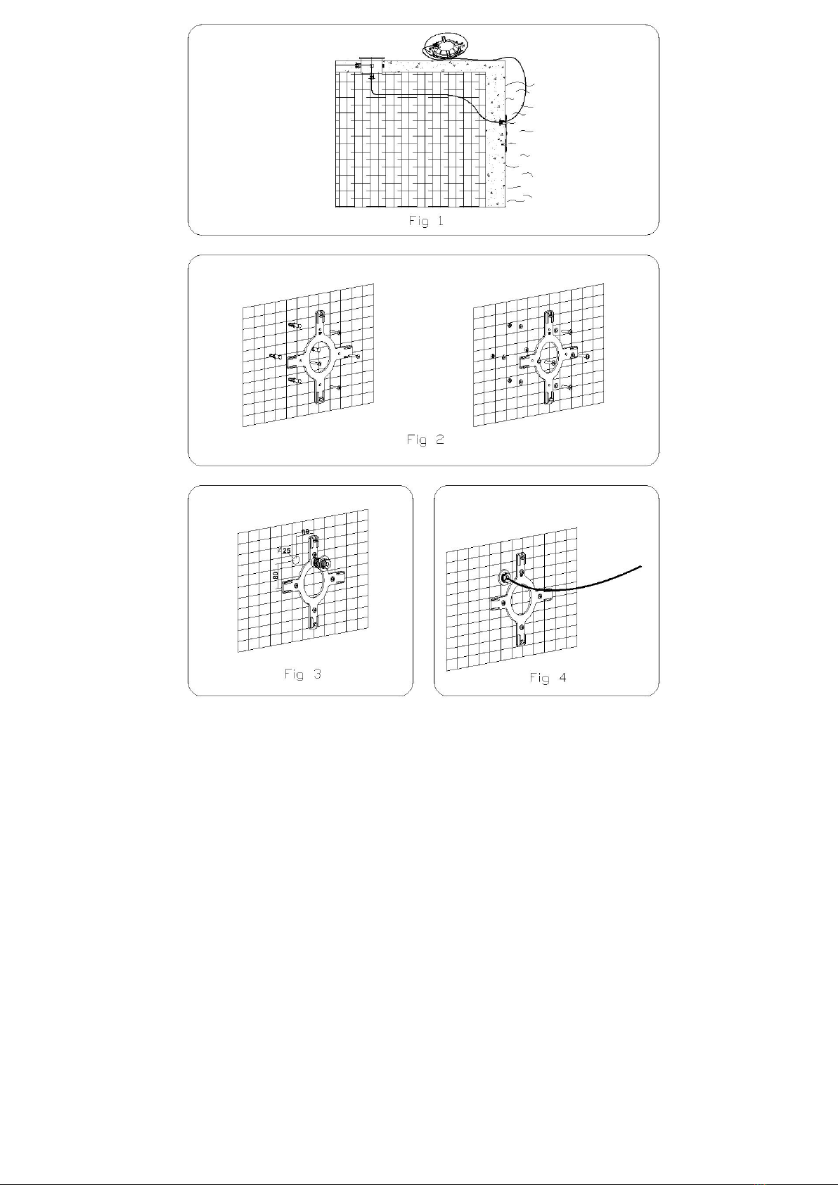
Aquant STANDARD Series Manual

FLAT UNDERWATER
LIGHT
STANDARD
SERIES
I
N
STA
LL
A
TI
ON
AN
D
M
A
I
N
TE
N
A
N
C
E
MA
NU
A
L

ENGLISH
I
M
PORTANT:
Th
e
ins
t
ru
ct
ion
m
a
nua
l
y
o
u
are
h
o
ldin
g
inc
l
ud
es
e
ss
e
n
t
ial
inf
o
r
m
a
t
ion
on
th
e
s
a
f
e
t
y
m
e
as
ur
es
to
be
im
plemented
for
in
sta
lla
ti
on
a
nd
sta
r
t-
up
.
T
herefo
r
e,
th
e
in
st
all
e
r
as
w
e
ll
as
th
e
us
er
mu
st
re
ad
the
ins
t
r
uct
io
ns
bef
or
e
beg
in
nin
g
i
nst
all
a
tion
a
nd
s
t
a
rt-up.
Keep
t
h
i
s
manu
a
l
for
fut
u
r
e
r
e
fe
re
nc
e.
To
ac
h
i
e
ve
opt
imum
per
forman
ce
of
the
S
t
anda
rd
Flo
o
dlamp
follow
t
he
i
nstru
cti
o
n
s
p
r
o
v
id
ed
b
e
l
o
w
:
1.
V
ERI
F
Y
T
H
E
CONTE
NT
S
OF
T
H
E
PA
CKING:
Th
e
fo
llow
i
ng
acce
ss
ori
es
are
inclu
d
e
d
in
sid
e
t
he
box:
C
onc
ret
e
p
oo
l
fl
oo
dlamp
Pr
e
f
ab
ri
ca
t
e
d
po
ol
f
l
oo
d
l
a
mp
Floodlamp
unit
Floodlamp
unit
Crosshead mount Crosshead mount
Bag of screws Bag of screws
2.
GE
NER
A
L
CHARACT
ERI
ST
I
CS:
Thi
s
fl
oo
dl
amp
ha
s
b
ee
n d
esigned
t
o
b
e
u
se
d
fully
su
bmer
ge
d und
e
rw
a
t
er
i
n
fr
es
h
w
a
t
e
r
sw
imming
po
ol
s.
It
is
a
C
l
ass
III
el
ect
ri
c
a
pp
a
ra
tu
s
w
i
th
ve
ry
low
sa
fet
y
vo
lt
age
(1
2
V
w
i
th
al
te
rn
a
t
in
g
curr
en
t).
Th
e
fl
oo
dl
amp
co
mpile
s
w
i
t
h IP
X8
degr
ee
of
pr
ot
e
c
ti
on
(r
esi
st
ance
to
pe
net
ra
tio
n
of
du
st,
sol
id
bo
di
es
an
d
humi
d
it
y)
at
a
no
minal
immer
s
ion d
ept
h
o
f
2
m.
T
h
i
s
f
l
oo
dlamp
comp
iles
wit
h
int
e
rn
a
t
ion
a
l
sa
fe
ty
sta
nd
a
rd
s
fo
r
ligh
t
s,
es
p
e
c
i
a
l
ly
th
e
EN
6059
8-2-
18
s
t
a
nd
a
rd
.
L
I
GHTS
PART
2:
SPECIF
I
C
REQU
I
REMENT
S
SE
CT
I
O
N
18
L
I
GHTS
F
OR
SWI
MMI
NG
POOLS
AND
SI
MI
L
AR
APPL
I
CAT
I
O
NS.
Th
e
man
u
f
act
ur
er
is
no
t
respon
si
bl
e
in
a
ny
cir
cumst
ance
s
fo
r
as
sem
b
l
y,
in
st
all
a
ti
on
or
sta
r
t
-up
of
an
y
el
ect
ri
c
comp
o
n
e
n
t
s
w
h
ic
h
hav
e
b
ee
n
in
se
rt
e
d
or
ha
ndi
ed
at
l
o
cat
io
ns
oth
e
r
th
an
its
ow
n pr
emis
es.
3.
I
N
ST
AL
L
A
T
I
ON:
N
eve
r
in
st
all
i
n
ve
rti
cal
po
sit
l
o
n
w
i
th
the
l
a
mp
fa
cin
g
d
o
w
n
w
a
r
ds,
I
n
orde
r
to
clea
r
l
y
ligh
t
a
p
oo
l
it
is r
e
c
o
mmen
d
e
d lo
in
st
a
ll
a
75W
f
l
oo
d
l
a
mp
ev
er
y
10
o
r
15
m²
o
f
wa
te
r
su
rfa
ce
.
In
swimming
pool
s
which
ar
e
especiall
y
deep,
a
75
W
floodl
amp
i
s
r
e
quir
ed
f
o
r
every
12
or
16
m³
of
water vol
ume.
In
ord
e
r
to
pr
ev
en
t
gl
are,
t
he
flo
o
d
l
amps
s
h
o
u
ld
be
i
nst
all
e
d
so
t
hat
th
ey
fa
ce
aw
ay
fr
om
th
e
r
eside
nc
e
o
r
us
ual
view
o
f
th
e
sw
imm
i
ng
po
ol.
In
t
he
eve
n
t
t
h
a
t
li
ght
in
g
i
s
u
se
d
in
t
rai
nin
g
or
c
o
mp
et
i
t
ion p
oo
l
s,
t
he
fl
o
odl
amp
s
s
h
o
u
l
d b
e
in
st
all
ed
on
th
e
sid
es
t
o
pr
ev
en
t
gl
ar
e
on
t
h
e
s
w
i
mme
rs
.
To
avo
i
d
th
e
need
to
em
pt
y
th
e
p
oo
l
to
ch
a
n
ge
t
he
l
a
mp
,
w
e
re
comm
e
nd
tha
t
t
he
f
l
o
odl
amp
be
i
n
s
t
alled
in
ar
eas
w
h
ich
ar
e
a
cc
ess
i
ble
from
th
e
up
pe
r
edg
e
o
f
th
e
p
oo
l
.
P
rior
t
o
i
nst
all
a
t
i
o
n
ve
rif
y
t
h
a
t
th
e
gl
an
d
se
al
ha
s
been
ful
l
y
t
i
g
h
t
en
ed.
T
h
e
f
l
oo
d
l
a
mp
shou
ld
b
e
p
l
aced
on
th
e
wa
ll
o
f
t
h
e
po
ol
a
t
ap
pr
ox
imat
e
l
y
700
mm
f
r
o
m
t
h
e
wat
e
r
su
r
f
ac
e
(F
ig
.
1)
.
Th
e
meth
o
d
o
f
fa
ste
n
i
ng
t
he
hous
i
ng
t
o
t
he
po
ol
w
a
ll
va
ri
es
depe
ndi
n
g
on
w
het
he
r
it
is
a
fl
oo
dlamp
f
o
r c
o
nc
re
te
pools
or
pr
e
f
a
b
ri
ca
ted
po
ol
s.
C
onc
ret
e
sw
immi
n
g
po
ol
Place the crosshead mount of the flat floodlamp in the designated place. Mark the holes. Drill with a
8 bit and insert the 4
fastening blocks.
Position the crosshead mount so that the word “TOP” is located on the upper part.
Use four 4.8x25 screws to secure the crosshead mount to the wall(Fig 2).
Place the conduit body in the upper left quadrant of the crosshead mount, in a ccordance with the measurements
shown in Fig 3.
P
r
efab
r
i
ca
ted
sw
i
mming
p
oo
l
Place the
crosshead mount of the flat floodlamp in the designated place. Mark the holes. Drill with a
8 bit.
Position the crosshead mount so that the word “TOP” is located on the upper part.
Use four M-6x35 screws with four washers to secure the crosshead mount to the inner wall of the swimming
pool.Place 4 butt joints between the mount and the liner. On the outer side of the swimming pool, insert 4 washers
and r nuts(Fig 2)
Place the conduit body in the upper left quadrant of the crosshead mount, in accordance with the measurements
shown in Fig 3. Use the butt point and the conduit nut to secure on the outer side of the swimming pool.

4.
AS
SEM
BL
Y
:
The floodlamp
is supplied with 2.5m of cable. It should be inserted through the conduit body(Fig 4), leaving
approximately 1.5m of cable in order to be able to remove the floodlamp to the border of the swimming pool if
handing or lamp change is required(Fig 1).
Wind the cable in counter-clockwise direction under the screen fastening clamps(Fig 5). Firmly secure the gland
seal nut (Fig 6).
In order to secure the floodlamp to the crosshead mount, ensure that the word “TOP” is located on the upper part.
First, insert the lower clamp of the screen in the crosshead mount.
Then, press on the upper part until the floodlamp is firmly inserted in the crosshead mount.
5.
MAINT
ENANCE:
T
o
r
e
m
ove
th
e
f
l
oo
d
l
a
mp
t
o
t
h
e
e
dge
of
th
e
s
w
imming
p
oo
l
(
F
ig
.
1)
Insert a screwdriver through the upper hole of the
ornament and press on the spline of the mount until the floodlamp is released.(Fig 7-8).
Pull up on the floodlamp until it is released from the lower groove and can be removed from the seimming pool.
Unlock the screw, Dismount the floodlamp by turning the key in counter-clockwise direction(Fig 9).
Pull on the lamp to separate it from the lamp holder. Connect the new lamp(Fig 10).
VERY IMPORTANT: To change the lamp, always use the cardboard protector and never touch the new lamp with your bare
hands.
Then, assemble the floodlamp in the opposite order of that described. Make sure that the butt joint and the transparent lens are
iinserted properly in the screen seat.
Align the word “TOP” on the ornament with the word “TOP” on the screen fastening.
Turn the ornament slightly to the right until it is fitted with the screen.
Wind 1..5m of cable in counter-clockwise direction under the screen fastening clamps. (Fig 5)
A
tten
ti
on:
B
e
for
e
a
ny
ha
ndl
i
ng
e
n
s
ur
e
t
hat
th
e
r
e
i
s
N
O
volt
age
s
upp
li
ed
t
o
t
he
f
l
oo
dlamp
.
T
h
e
n
e
w
lamp
shou
ld
h
ave
th
e
sa
m
e
ch
a
r
a
c
t
e
ris
t
i
c
s
as
t
h
at
su
pp
lie
d
with
t
h
e
f
l
oo
d
l
a
mp
,
(75W 12V halogen lamp).
In
orde
r
to
e
n
s
ur
e
full
w
a
ter
t
i
ght
ne
ss
,
clea
n
th
e
se
at
o
f
the
floodlamp lens joint
or
r
e
pla
ce
t
his
if
any permanent
deformation or notches are visible.
6.
ST
ART
-U
P:
E
nsure
t
h
a
t
th
e
vo
l
ta
ge
t
he
lamp
re
c
e
iv
es
i
s
n
eve
r
gre
a
t
er
th
an
12
V.
Th
e
flo
o
d
l
amp
sh
o
u
ld
o
n
l
y
oper
at
e
und
e
rw
at
er
w
h
il
e
se
cu
re
d
to
t
he
ver
ti
cal
w
a
ll
s
o
f
th
e
p
ool.
N
e
ver
sw
itc
h
on
t
he
f
l
oo
d
l
a
mp
if
i
t
is
no
t
un
de
r
w
at
er
.
7.
SAF
ET
Y
WARN
I
N
GS:
Th
e
pe
rs
on
s
who
a
r
e
i
n
ch
ar
ge
of
a
ss
e
mbl
y
s
h
o
u
ld
ha
ve
the
re
qui
re
d
qual
if
ic
atl
o
n
s
f
o
r
t
h
is
t
y
p
e
of
w
o
rk.
If
th
e
e
nd
ca
b
l
e
of
t
h
is
li
g
h
t fitti
n
g
is
d
a
ma
ge
d,
it
sh
oul
d
o
n
ly
be
r
e
pla
ce
d
b
y
th
e
manuf
ac
tu
re
r,
its
t
ec
hni
ca
l
servi
ce
or
b
y
a
similar
l
y
qu
alif
ied
p
e
r
s
o
n
,
to
av
oid
an
y
da
ng
er.
Avoid
maki
ng
co
nt
act
w
i
th
t
he
ele
c
t
r
i
c
v
o
lt
ag
e.
C
o
mply
w
it
h
t
he
c
u
rr
en
t
st
anda
rd
s
r
e
g
ard
in
g
a
ccide
nt
pre
v
e
n
ti
o
n
.
I
n
th
is
r
e
g
a
r
d
,
t
h
e
I
EC
364-
7-
702
s
t
anda
rd
s
mu
st
b
e
o
b
s
e
r
v
e
d
.
WI
R
I
NG
I
N BUI
L
DI
NGS.
SPECI
AL
WI
RI
NG
.
SWI
MMI
NG
POOL
S.
Any
o
p
e
r
at
io
n
r
e
l
a
ted
t
o
t
he
m
a
in
ten
a
n
ce
or
re
pla
ce
men
t
o
f
p
a
rt
s
s
h
o
u
ld
be
perf
orm
ed
w
it
h
t
he
flo
o
d
l
amp
disc
o
nn
ec
t
e
d
fr
om
the
ele
c
t
r
ic
pow
e
r
sys
tem.
D
o
not
handle
w
it
h
w
e
t f
ee
t
.
Th
e
manufact
urer
is
no
t
re
spon
sib
l
e
in
a
ny
c
i
r
cums
t
an
ce
s
for
as
sem
bl
y,
ins
t
allation
or
s
t
ar
t-
up
o
f
an
y
el
ec
tric
comp
o
n
e
n
t
s
w
hich
have
b
ee
n
in
se
rt
e
d
or
handled
at
l
o
cat
io
ns
othe
r
th
an
Its
ow
n
pr
emi
s
e
s
.

ENGLISH Halogen Concrete UWL
ID.
CODE
DESCRIPTION
Q.
ID.
CODE
DESCRIPTION
Q.
1
2
3
4
5
6
7
8
9
10
11
12
08020601R0001
45843R0002
45843R0011
DIN7985 M2X8
45843R0008
DIN7981 ST3.5X9.5
ST4.8X38
45843R0007
8*40
45843R0006
45843R0015
45843R0003
Face plate
rin
g
Clear lens
Silicon gasket
Screw DIN 7985 A2 M-2x8
Rear protection screen
Screw DIN 7981 3.5x9.5
Screw DIN 7981 A2 4.8x38
Mounting bracket
Screw anchor S-6
Key
Electrical cable 2.5mx1.5
Conduit connector
1
1
1
1
1
1
4
1
4
1
1
1
13
14
15
16
17
18
19
45843R0001
45843R0014
45843R0009
DIN7981 ST2.9X9.5
DIN934 M2
45843R0012
45843R0013
Cable gland gasket
Cable gland nut
Reflector
Screw DIN 7981 2.9x9.5
Nut DIN 934 A2 M-2
Lamp holder
Halogen lamp 12V 75W
2
2
1
3
1
1
1

ENGLISH Halogen Prefabricated UWL
ID.
CODE
DESCRIPTION
Q.
ID.
CODE
DESCRIPTION
Q.
1
2
3
4
5
6
7
8
9
10
11
12
13
14
08020601R0001
45843R0002
45843R0011
DIN7985 M2X8
45843R0008
DIN7981 ST3.5X9.5
DIN7985 M6X25
45843R0017
45843R0007
45843R0018
DIN125 A6.4
DIN934 M6
45843R0006
45843R0015
Face plate
rin
g
Clear lens
Silicon gasket
Screw DIN 7985 A2 M-2x8
Rear protection screen
Screw DIN 7981 3.5x9.5
Screw DIN7985 M6X25
O ring
Mounting bracket
Gasket rubber
Washer DIN125 A6.4
Nut DIN934 M6
Key
Electrical cable 2.5mx1.5
1
1
1
1
1
1
4
4
1
4
8
4
1
1
15
16
17
18
19
20
21
22
23
24
45843R0016
45843R0005
45843R0003
45843R0001
45843R0014
45843R0009
DIN7981 ST2.9X9.5
DIN934 M2
45843R0012
45843R0013
Wall conduit nut
Flat gasket
Conduit connector
Cable gland gasket
Cable gland nut
Reflector
Screw DIN 7981 2.9x9.5
Nut DIN 934 A2 M-2
Lamp holder
Halogen lamp 12V 75W
1
1
1
2
2
1
3
1
1
1

ENGLISH LED Concrete UWL WITH REMOTE CONTROLLER
ID.
CODE
DESCRI
P
TION
Q
.
ID.
CODE
DESCRI
P
TION
Q
.
1
2
3
4
5
6
7
8
9
10
08020601R0001
45843R0002
45843R0011
45843R0008
DIN7981 ST3.5X9.5
ST4.8X38
45843R0007
8*40
45843R0006
45843R0015
Face plate
rin
g
Clear lens
Silicon gasket
Rear protection screen
Screw DIN 7981 3.5x9.5
Screw DIN 7981 A2 4.8x38
Mounting bracket
Screw anchor S-6
Key
Electrical cable 2.5mx1.5
1
1
1
1
1
4
1
4
1
1
11
12
13
14
14
14
14
15
16
45843R0003
45843R0001
45843R0014
08020603R0001
45845R0001
08020604R0001
45846R0001
DIN7981 ST2.9X9.5
08020607R0002
Conduit connector
Cable gland gasket
Cable gland nut
LED lamp 144 white
LED lamp 246 white
LED lamp 144 color
LED lamp 246 color
Screw DIN 7981 2.9x9.5
Remote controller
1
2
2
1
1
1
1
3
1

ENGLISH LED Prefabricated UWL WITH REMOTE CONTROLLER
1
2
3
4
5
6
7
8
9
10
11
12
08020601R0001
45843R0002
45843R0011
45843R0008
DIN7981 ST3.5X9.5
DIN7985 M6X25
45843R0007
45843R0017
DIN125 A6.4
45843R0018
DIN934 M6
45843R0006
Face plate
rin
g
Clear lens
Silicon gasket
Rear protection screen
Screw DIN 7981 3.5x9.5
Screw DIN7985 M6X25
Mounting bracket
O-ring
Washer DIN125 A6.4
Gasket rubber
Nut DIN934 M6
Key
1
1
1
1
1
4
1
4
8
4
4
1
13
14
15
16
17
18
19
19
19
19
19
20
21
45843R0015
45843R0016
45843R0005
45843R0003
45843R0001
45843R0014
08020603R0001
45845R0001
08020604R0001
45846R0001
08020607R0001
DIN7981 ST2.9X9.5
08020607R0002
Electrical cable 2.5mx1.5
Wall conduit nut
Flat gasket
Conduit connector
Cable gland gasket
Cable gland nut
LED lamp 144 white
LED lamp 246 wihte
LED lamp 144 color
LED lamp 246 color
LED lamp 246 color remote
Screw DIN 7981 2.9x9.5
Remote controller
1
1
1
1
2
2
1
1
1
1
1
3
1


TECHNICAL
CHARAC
TERISTICS
DESCR
IPT
I
ON
STAND
A
RD
Rated
vol
t
age
12V
Current
sup
l
y
AC
Power
Halogen
12V
AC
75
W
LED
12V
AC
21
W
Protecti
o
n
CLASE
III
IPX8
TO
BE
USED
ONLY
WITH
A
SECURIY
TRANSF
ORMER
THE
UNDERWATER
LIGHT
NEVER
T
O
BE
SWITCHED
O
N IF IT IS
NOT
SUBMERGED
We
reserve
to
ch
an
ge
al
l
or
p
a
rt
of
th
e
arti
cl
es
or
c
o
n
t
e
nts
of
th
i
s
d
ocu
m
e
n
t
,
w
i
th
ou
t
pr
i
o
r
n
o
ti
ce.
Table of contents
Other Aquant Underwater Lighting manuals