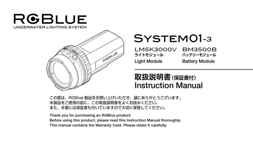
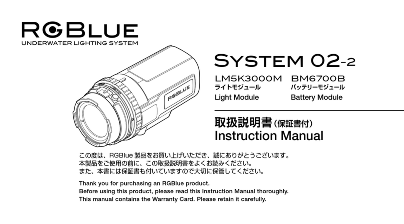
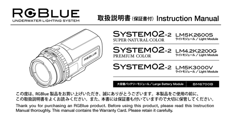
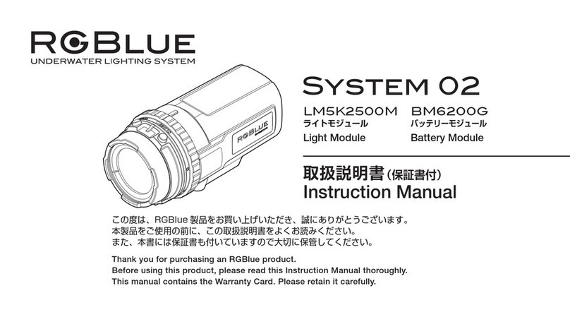
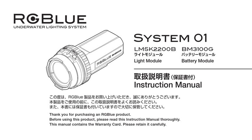
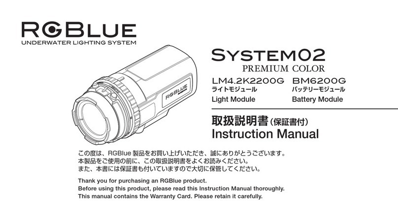
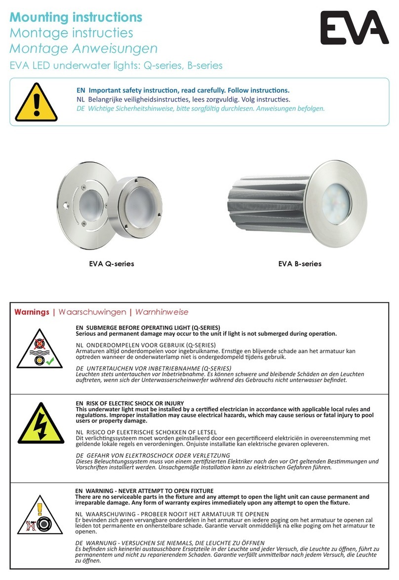
RGBlue System 01/02:re User manual

Important
Before Using the Product
Product Number
S01RE-SNC
S01RE-PC
S02RE-SNC
S02RE-PC
S01RE-TL-SNC
S01RE-TL-PC
S02RE-TL-SNC
S02RE-TL-PC
S01RE-SB
S02RE-SB
Instruction Manual

2
Introduction
Thank you for purchasing this product — RGBlue System 01/02:re, RGBlue System 01/02:re Twin Light, or RGBlue
System 01/02:re Spot Beam.
Read this manual carefully before using this product.
• Duplication of the contents of this manual without permission from RGBlue is prohibited except for personal use.
• The contents of this manual may be subject to change without prior notice.
• RGBlue assumes no liability against any claim from a third party for any damage caused by improper use of
this product.
• RGBlue assumes no liability for any damage resulting from a malfunction of this product or any other reason
including disassembly, repair, or modication by a third party other than those parties designated by RGBlue.
WARNING : This product contains electronic circuitry and a lithium-ion battery. Do not attempt to disassemble or
modify it. This could pose a risk of electric shock or injury.
CAUTION : If any liquid or a foreign object gets inside the product, stop using it immediately, turn OFF the power
and contact your dealer or RGBlue.

Important
Before Using the Product
3
S01RE-SNC
StandardBatteryModule BM3521S
LM5K2600S2 LM4.2K2200G2 LM5K-SP17-2
S01RE-TL-SNC
S02RE-TL-SNC
S02RE-SB
S01RE-SBS01RE-PC
S02RE-PC
S01RE-TL-PC
S02RE-TL-PC
S02RE-SNC
LargeBatteryModule BM6721L
Product Lineup

Important
Before Using the Product
4
Contents

5
Indicates a prohibited action.
Indicates a mandatory action that must be followed.
Followed by a description about the possibility of
equipment damage.
Followed by information on operation and maintenance
you need to know.
Indicates an imminently hazardous situation which, if not
avoided, could result in death or serious injury.
Indicates a potentially hazardous situation which, if not
avoided, may result in death or serious injury.
Indicates a potentially hazardous situation which, if not
avoided, may result in serious injury or equipment damage.
Important
● This "Safety Precautions" manual contains information critical to your safety. Be sure to carefully read all
information provided here.
● The following symbols describe the degrees of risk of injury and nancial damage that may result if the
information given under each symbol is not observed.
This manual shows the levels of risk and danger by dividing them as follows.
DANGER
DANGER
WARNING
CAUTION

6
WARNING
CAUTION

7
● Products bearing this symbol use a rechargeable battery (lithium-ion battery).
● Recyclable and precious materials are used in the lithium-ion battery.
● When you are going to dispose of the product, be sure to unplug the power plug from the AC outlet
and turn ON the power to fully discharge the battery so that the product no longer operates. Once the
rechargeable battery has been discharged, remove it as instructed in the product manual.
● Do not dispose of the rechargeable battery as household waste. Recycle it in accordance with local
regulations.
1. Loosen the screws with a screwdriver and
remove the cap.
2. Remove the connector wired to the Battery
Module from the circuit board on the back
of the cap.
BM6721LBM3521SBM6721LBM3521S

8
3. Use a Phillips screwdriver to unscrew the screws.
Take o the ring and remove the connector
wired to the battery from the circuit board
inside the Battery Module.
3-1. Remove the side plates and screws that
x the lock ring.
3-2. Remove the lock ring.
4. Take the battery out of the Battery Module.
BM3521S
BM6721L
BM3521S BM6721L

9
Before Using the Product
WARNING
Before Using the Product
①
②
LM5K2600S2
LK4.2K2200G2
⑥BM3521S ⑦BM6721L
③
④
LM5K1300S2
LK4.2K1100G2
⑤LM5K-SP17-2
S01RE-SNC A ① B ⑥ C E
S01RE-PC A ② B ⑥ C E
S02RE-SNC A ① B ⑦ C E
S02RE-PC A ② B ⑦ C E
S01RE-TL-SNC A ③ B ⑥ D E F
S01RE-TL-PC A ④ B ⑥ D E F
S02RE-TL-SNC A ③ B ⑦ D E F
S02RE-TL-PC A ④ B ⑦ D E F
S01RE-SB A ⑤ B ⑥ C E
S02RE-SB A ⑤ B ⑦ C E
* For O-ringmaintenance
* 60W : rated at 3A

10
LM5K2600S2
LM4.2K2200G2
LM5K1300S2
LM4.2K1100G2
LM5K-SP17-2
1
1
1
18
17
5
6
5
6
16
15
14
20
19
13
13
2
2
2
3
3
3
12
11
10
10
11
11
10
9
9
9
5
67
7
7
8
8
8
13
14
4
4
4
Before Using the Product
1 LED
2 UP button
3 DOWN button ............ Increases and decreases the
light intensity. Also turns the
power ON and OFF.
4 Indicator ..................... Indicates power status,
battery level, and error
occurrence.
5 Electrical contact ....... Wipe o any moisture if
these are wet.
6 Optical communication receiver ........ Used when
the optional remote control
is used.
7 Lock lever ................... Used when the light module
is removed from the Battery
Module.
8 Tripod thread
9 O-ring ......................... Prevents water from entering
the connection between the
Light Module and Battery
Module.
10 Drip-proof gasket .... Prevents water from entering
the electrical contacts if the
O-ring is wet.
11 Light Module cap .... Closing this cap does not
waterproof the module.
12 Protector
13 Reinforced glass
14 Reector
15 Light head(thread diameter : M25)
16 Clamping screw
17 Cable
18 Adapter Ring
19 Beam attachment
20 Rubberprotector

11
Before Using the Product
1 Battery Module cap ..................... Closing this cap does not waterproof the module.
2 Electrical contact ......................... Wipe o any moisture when these are wet. If short-circuited by seawater, for
example, this will be detected by the safety circuit and the module will be
temporarily inoperable .
Note: For details on failure recovery , see “About the Recovery Function” in
the “Maintenance after Use” manual.
3 Lock ring
4 Bottom plate
5 Bottom plate xing screws ........Use a 2.0mm Allen wrench to remove these screws.
6 Charge terminal ..........................Wipe o any moisture before charging the battery.
7 Over-pressure valve
8 Side plate
BM3521S
BM6721L
1
1
2
2
3
3
8
4
4
6
5
6
7
7
5

12
Before Using the Product
Removal
Turn the cap in the 【OPEN】direction and pull it.
Attachment
1.Align the indicator on the Light Module with
OPEN index【◯】on the cap and t the cap
on the light head.
2. 2.Turn the cap in the
【CLOSE】 direction as far
as it goes.
Removal
1.Turn the lock ring until the 【OPEN】.
2【OPEN Index ◯】is aligned with the【 index Ⓐ】 pull
out the cap.
indexⒶ
Attachment
1.Align the【OPEN Index ◯】on the lock ring
with the【 index Ⓐ】.
2.Align the tooth on the back of the cap with the
【 index Ⓐ】 and t the cap on the lock ring.
3.While pushing the cap in place, turn the lock
ring until the 【CLOSE index ●】 is aligned with
the 【 index Ⓐ】.

13
Before Using the Product
IPX6 is a liquid ingress protection standard with which water
projected in jets from any direction shall have no harmful e ects.
Withstanding water depth:
100 meters
CAUTION

14
Before Using the Product
CAUTION
1. Remove the O-ring with your thumb and nger.
2. Check that the O-ring is free of dirt, foreign object, crack or damage.
3. Clean the O-ring groove with a cotton swab, etc.
4. Apply special grease on the O-ring.
5. Attach the O-ring.
6. Check that the O-ring applying surface of
the Battery Module is free of foreign object
and connect the modules.

15
1. After aligning the OPEN index ◯ with the index Ⓐ
2. Battery Module and the OPEN index ◯ with the indicator on the Light Module, t the Light Module
all the way in.
3. Turn the lock ring so that the CLOSE index ● is aligned with index Ⓐ . When a “click” sound is heard,
the ring is locked in position.
OPEN
1. While pushing the lock lever on the Light Module in the direction of the arrow, turn the lock ring in
the “OPEN” direction.
2. Align “OPEN” on the lock ring with index A on the Light Module. Then remove the Light Module from
the Battery Module.

16
The indication varies depending on the light intensity level. This is because of the
product speci cations and not a malfunction.
Before Using the Product
WARNING
1. Connect the AC adapter and the charger
adapter with the USB PD cable.
2. Attach the charger adapter to the Battery
Module so that their electrical contacts become
engaged.
3. Plug the AC adapter into a power outlet.
4. The charge indicator on the charge adapter
lights to indicate the start of charging.
5. Charging is complete when the charge
indicator on the charge adapter extinguishes.
○An AC adapter is not included. Use the optional
AC adapter (RGB-PDAC01). A commercially
available USB PD AC adapter (30W, 15V, 2A) can
also be used.

17
● For inquiries, see contact information below.
AOI Japan Co., Ltd.
Reception hours: 10:00–17:00, Monday–Friday,
(Closed: Saturday,Sunday and national holidays)
2F, Parktower Yokohama Portside 2-1 Kinko-cho, Kanagawa-ku,
Yokohama, Kanagawa, Japan 221-0056
Other manuals for System 01/02:re
2
This manual suits for next models
12
Table of contents
Other RGBlue Underwater Lighting manuals

RGBlue
RGBlue System 02-2 User manual

RGBlue
RGBlue System 01 User manual

RGBlue
RGBlue SYSTEM02-2 SUPER-NATURAL COLOR User manual

RGBlue
RGBlue LM4.2K2200G User manual

RGBlue
RGBlue System 01/02:re User manual

RGBlue
RGBlue System 02 Premium Color User manual

RGBlue
RGBlue System 01/02:re User manual

RGBlue
RGBlue System 02 User manual

RGBlue
RGBlue System 01-3 User manual