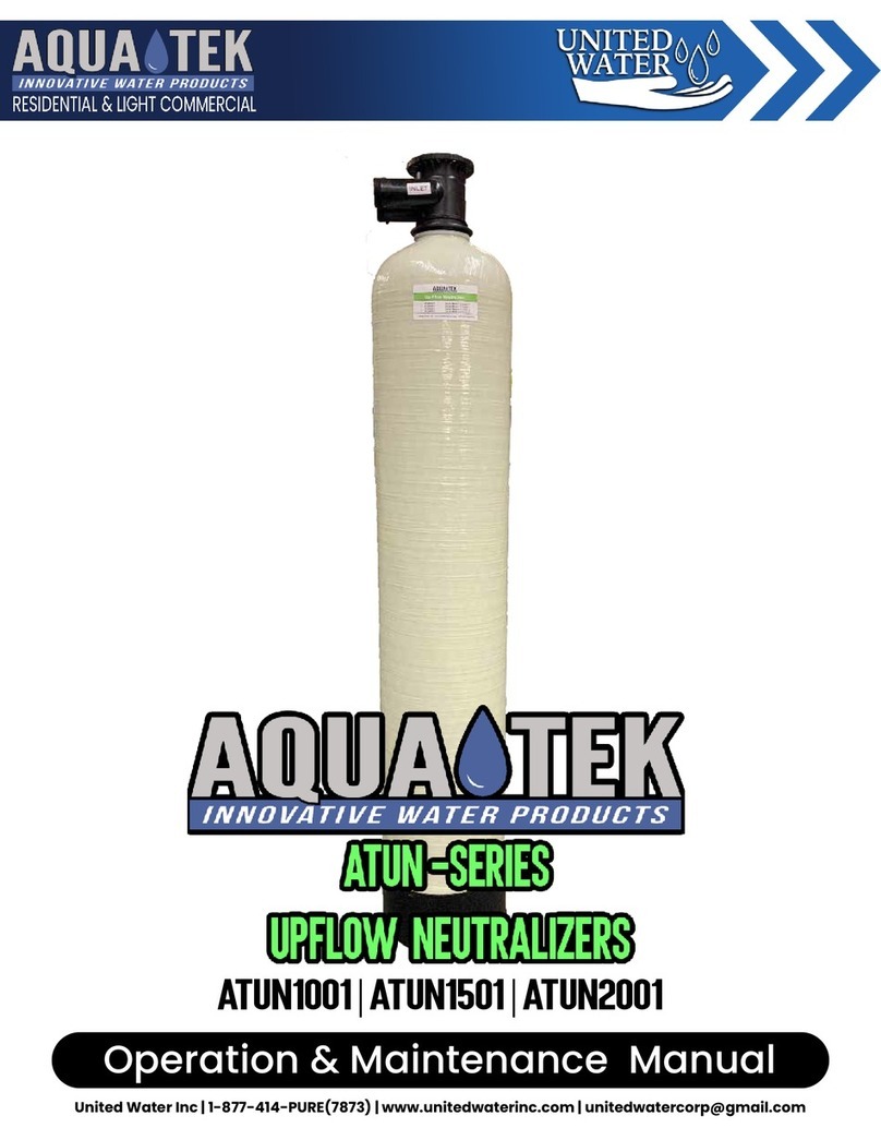
Aquatek ATAIOIF Series Manual

Operation & Maintenance Manual
ATAIOIF

UNITED WATER INC.
AquAtek AtAIOIF-SerIeS uSer GuIde
2
Table of Contents
Introduction 4
About Your Filter 5
Installation Guide 6
Media Fill/Replacement 8
System Startup 9
Programming 10
Manual Regeneration 12
Bypassing Filter 13
Trouble Shooting Guide 14
Manufacturer’s Limited Warranty 16

UNITED WATER INC.
AquAtek AtAIOIF-SerIeS uSer GuIde
3
***ATTENTION***
ATAIOIF System Specifications & Warnings
System Specifications
Water pressure: 40 psi minimum 100 psi
Maximum Water Temperature: 40°F to 95°F
Electrical Requirements:
Supply Voltage: 120V
Supply Frequency: 60Hz
Output Voltage: 12V AC
Output Current: Maximum 3.0 Amps
Water Meter:
Pipe Size: 3/4”-1”
Accuracy: ± 5%
Minimum Flow : 0.25 GPM
Control Valve to Tank Connection: 2.5”-8UN Control
Valve Distributor Pipe Connection: 1”
Circuit Board Memory: Non-volatile EEPROM (Electrical Erasable Programmable Read Only Memory)
Compatible with the following typical concentrations of regenerant chemicals: Sodium Chloride, Potassium
Chloride, Potassium Permangenate, Sodium Bisulfite, Chlorine and Chloramines
***WARNINGS***
LThe control valve and fittings are not designed to support the weight of the system or the plumbing.
LDo not use Vaseline, oils, other hydrocarbon lubricants or spray silicone anywhere. A silicone lubricant
may be used on black O-rings. Hydrocarbons such as kerosene, benzene, gasoline, etc., may damage
products that contain O-rings or plastic components. Exposure to such hydrocarbons may cause the
products to leak. Do not use the product(s) contained in this document on water supplies that contain
hydrocarbons such as kerosene, benzene, gasoline, etc.
LThe water meter should not be used as the primary monitoring device for critical or health effect appli-
cations.
LDo not use pipe dope or other sealants on threads. Teflon tape is recommended to be used on all
threads. Use of pipe dope may break down the plastics in the control valve.
LThis system is not intended for use where water is microbiologically unsafe or with water of unknown
quality.
LWARNING! Electrical Shock Hazard! Prior to servicing equipment, disconnect power supply.
LIf incorrectly installed, operated or maintained, this product can cause injury or property damage. Those
who install, operate, or maintain this product should be trained in its proper use and should read the
entire manual before attempting to install, operate, or maintain this product.

UNITED WATER INC.
AquAtek AtAIOIF-SerIeS uSer GuIde
4
Please Read Manual First
Before you operate your Aquatek Iron Filter, read this manual to become familiar with the
device and its capabilities.
Installation or maintenance done on this system by an untrained service person can
cause major damage to equipment or property damage. Not adhering to the recom-
mended service/maintenance can cause damage to equipment or property damage. It
is important to maintain your sulfur and iron filter. To properly maintain your system have
a water technician change the filter media when necessary. (Check with your dealer.) If
your filter media is not working properly, or is not replaced frequently enough, it has po-
tential to grow bacteria that can end up in your water system. A water technician can tell
you how often the filter media needs replacing.
This manual is intended to be a practical reference guide. It contains information about
operating this water filtering system—including installation and start-up instruction for the
installer and programming, regenerations, settings and troubleshooting for the home-
owner. The Sulfur and Iron Water Filter is designed for long-term use. To determine when
to change the filter media, contact your dealer. Every system encounters different water
conditions therefore every filtration system will have different timetables for replacing the
filter media. Make sure you have a water technician change your filter media and periodi-
cally test for effectiveness.
Introduction
1Zeolite
Background
Zeolite filter media offers advantages over conventional sand, sand & anthracite or multimedia for gravity flow or pres-
sure vessel beds. Historically, natural zeolite mineral deposits were discovered in the 1950’s and zeolite has been quary,
mined, crushed, air-dying and sieve sized to produce commercial products for >30 yrs. Natural zeolite (Clinoptilolite) is
crystalline, aluminum oxide/silicn oxide classified as a crystalline, molecular sieve, mineral consisting of hydrated Ca2
(Na2 or K2) Al8 Si28O72•24 H2O. Most zeolite deposits are low quality and can’t be used as molecular sieve beds or wa-
ter filtration media. Zeolite has been used for water softening and to remove NH-4 ion using slow flow rates (1-2 gpm/ft2
) and Na-ion regeneration cycles. Since 1985 numerous technical and engineering studies have demonstrated the utility
of zeolite mineral as an effective water filter media.
Zeolite Filter Media
Zeolite Filter Granules are a high quality, granular, filter media that achieves superior filtration & solids loading com-
pared to conventional filter media. The zeolite media is from a unique, mineral deposit in the western USA having high
porosity, hardness, high surface area (~28m2 /gm) and surface, micromineral, projections that make it an ideal water
filtration media (fig 2 & 3).. The 14 x 40 mesh
filter media has a dry bulk wt.55 lb/ft3 & is attrition resistant. The zeolite mineral is classified under 21CFR Part 182.2729 &
40 CFR Part 180. as GRAS (Generally Recognized As Safe) and is NSF Standard 61 Listed.

UNITED WATER INC.
AquAtek AtAIOIF-SerIeS uSer GuIde
5
About Your Filter
How Does my Sulfur and Iron Filter Work?
This filter uses a special blend of calcium, magnesium oxide
and sand that is highly effective for removal of hydrogen sul-
fide and iron. The filter uses an air chamber within the tank to
capture and oxidize the elements and then filter them through
the media bed. An automatic backwashing system will clean
the media of the sulfur and iron leaving the system clean, and
the water you drink odor free.
A Control Valve
B Mineral Tank All Aquatek Iron Filters are comprised of two primary
components: (A) Control Valve, (B) Mineral Tank.
A. Control Valve: Your control valve automatically
performs the 3 primary operations which are com-
monly referred to as cycles. These operations/cycles
are:
1. Pre-Treatment Oxidation: Air is injected into the
mineral tank which causes contaminants in the
water to precipitate and settle out. Precipitated
contaminants are much larger and clump to-
gether so they can be removed through filtration.
2. Service / Filtration: The oxidized water is now
flushed through the media bed comprised of Ze-
oLite1(see pg 4) and gravel underbedding which
mechanically strains the contaminants like iron,
manganese, & hydrogen sulfide.
3. Backwash: Once the media bed has reached its
predetermined limit of filtration it cleans and re-
plenishes itself through backwashing. Backwash-
ing is a forceful flush that removes the filtered
contaminants and then flushes then down the
drain.
B. The Mineral Tank: The mineral tank contains the
filtration media and is where the the treatment of
the water takes place during the 3 stages mentioned
above.

UNITED WATER INC.
AquAtek AtAIOIF-SerIeS uSer GuIde
6
Installation Guide
Pre-Installation Checklist
1. A standard electrical outlet (120V/160Hz) must be located within 12’ of installation site.
2. A functioning floor drain, washer sand pipe or suitable location for waste water discharge must be located with-
in 20’ of installation site.
a. All plumbing should be done in accordance with local plumbing codes. The pipe size for the drain line should
be a minimum of 1/2”. Backwash flow rates in excess of 7 gpm or length in excess of 20’ require 3/4” drain line.
3. It is recommended a working pressure reducing valve be installed on the inlet water line that supplies the water
filter
4. Note: The warranty is void if the system is exposed to water pressure in excess of 100 psi and/or water tem-
peratures in excess of 95° F
5. Important: Protect your Fitler and the entire drainline from freezing temperatures. The temperature at the loca-
tion of the system should never be below 40° F
WARNING! DANGER: If your unit should freeze, do not attempt
to disassemble it. Call us first 877-414-PURE
Installation
1. Floor Space: Make sure the floor space that has been selected to install the water filter is clean and
on a level surface. In some cases, your media may be shipped seperatelty. Place media Tank in rela-
tive position of end install, and see “Media Fill/Replacement” on page 8.
2. Leveling the System: Mineral tanks are fitted with an adjustable leveling base, if tank is not vertical/
straight lift tank 1-3 inches off the floor and gently release tank back on to the floor (repeat until stright
up and down).
3. Connection Kit: The standard connection kit supplied with the water softener will be a 1” plastic el-
bow connection kit. (See Figure 1) Other connection kits are available.
4. Plumbing Preparations: Unscrew the two plastic nuts (#1) and pull on the two brass connectors
(#4) to remove them from the bypass assembly. Next remove the white plastic rings (#2) and the
O-rings. (#3) (See Figure 2)
• Solder at least 6” of pipe to the brass connectors before reassembly. (See Figure 2)
• After soldering is complete, cool the pipe and connectors. Slide the plastic nuts (#1) over the brass connectors (#4). Place
the white plastic split rings (#2) into the grooves closest to the end of the brass connectors (#4). Reassembly the connection
kit onto the bypass assembly.
Warning: When assembling the installation-fitting package (inlet and outlet), connect the fitting to the plumbing system first
and then attach the nut, split ring and O-ring. Heat from soldering or sol- vent cements may damage the nut, split ring or o-
ring. Solder joints should be cool and solvent cements should be set before installing the nut, split ring and O-ring. Avoid getting
primer and solvent cement on any part of the O- rings, split rings, bypass valve or control valve.
5. Plumbing: When connecting the water filter to the existing plumbing, make sure the inlet water is
connected to the inlet of the filter. Arrows on the valve body indicate direction of flow. Make sure the
bypass valves are in the correct position See Figure 3. An internal check valve is supplied with the sys-
tem and has already been installed in the inlet of the control valve to ensure that the air charge in the
top of the tank does not escape backwards out the inlet.
Note: All plumbing should be done in accordance with local plumbing codes.
Warning: The control valve, fittings and/or bypass are designed to accommodate minor plumbing mis-aligments
but are not designed to support the weight of a system or the plumbing.

UNITED WATER INC.
AquAtek AtAIOIF-SerIeS uSer GuIde
7
Fig. 1
Installation CONT.
6. Locate Polytube Insert: Now that the water softener is connected to the existing plumbing, the drain
line may be connected. First, locate and remove the polytube insert (#2) from the gray cable on the
left side of the control valve. (See Figure 4)
7. Connecting the Drain Line: Slide plastic nut (#3) over the permanent drain tubing and place the
polytube insert (#2) into the end of the drain tubing. Insert the drain tubing into the drain elbow fitting
(#4) and tighten plastic nut (#3) hand-tight plus 1/2 turn with pliers. Caution: Do Not Over-tighten.
(See Figure 4)
8. Drain Line Specs: If the distance from the water filter to the drain is greater than 20’ the drain line
size must be increased to 3/4”. The threads on the drain elbow fitting are 3/4” male NPT and can be
used in lieu of the 1/2” plastic nut and insert. If the drain line must run overhead, the maximum height
of the drain line should not exceed 8’ above the top of the water softener.
9. Air Gap: The drain line must have an approved air gap to prevent the possibility of a cross connec-
tion to the sewer. (See Figure 5)
10. IMPORTANT: Special precautions must be made when connecting the drainline. During backwash,
high volumes of air and water escape rapidly, causing a flexible drain line to whip and thrash. Rigid
drain piping is highly recommended.
Fig. 2 (optional)
Fig. 3 Fig. 4
Fig. 5
***Disclaimer*** United Water strongly recommends that each system be installed by a
licensed and knowledgeable professional. Failure to do so could result in property dam-
age, equipment failure and potentially void warranty.
All systems MUST be installed in accordance with local and state plumbing codes.

UNITED WATER INC.
AquAtek AtAIOIF-SerIeS uSer GuIde
8
These instructions are to help guide you through the steps for initial installation or replacement of
the media in your filter or softener. Please check to ensure that all the parts have been included
by reviewing the labels that are attached to the filter (e.g. xxx bed - container 1 of 3, 2
of 3, 3 of 3). Container may contain more than one media. lf you have any questions regarding
the installation or replacement of your media bed, please contact your local dealer for assistance.
Fig. 1 - The riser
(distributor) remains
inside the tank seated
in the depression at
the bottom. The riser
should be capped to
prevent resin beads
from getting inside.
Fig. 2 - Fill support
bed first (if supplied)
Fig. 3 - The media will
not always spill down
inside the tank and
may need to be swept
inside
1. Loading the Media Pak
Place the distributor tube into the media tank and
plug the end of the distributor tube with a tape to
prevent media from entering it. Make sure that
distributor tube is inside the tank and seated in a
depression at the bottom of the tank. (If replacing the
media. inspect the distributor for any damage to the
slots in the cone or plugging - clean if necessary.)
Plug tube with a tape
Remove after media
is loaded.
Plug the media tube with tape to prevent the media
from getting inside the tube. Place the media into
the tank in the order indicated on the next page for
the type of unit that matches yours. The large funnel
(supplied) makes filling the tank easier and heater.
(Or an empty 1 gallon or 4 liter container with the
bottom cutout makes a good funnel.) Fill support bed
(if supplied) first. During the filling process, ensure
the distributor tube stays on the bottom of the tank,
reasonably centered. Remove the
tape from the distributor once media
is loaded. Whenever possible, fill the
tank outdoors to avoid problems with
dust. lf filling indoors, a dust mask
should be worn.
2. Placing the Unit in Service
Once the tank is filled, remove the cover from the
distributor and clean off the top of the tank. Place
the control valve onto the tank, ensuring the
distributor fits into the valve properly. Tighten the
valve onto the tank using moderate force. Applying
some household liquid soap to the main seal
O-ring will ease assembly. Attach the plumbing to
the inlet and outlet of the valve as necessary
Follow the installation and operating instructions
for system start-up found in your Owners Manual
or slowly fill the tank in the backwash position and
allow it to flush the air and fine particles down the
drain until the drain water appears clear (about 20
minutes). Once the drain runs clear, plug in the
electrical cord, open the inlet valve fully and allow
the valve to finish its cycle. Check for any leaks
and reset the time of day on your controller.
3. Depressurizing the Unit*
The first step is to loosen the bed and depressurize
the unit. Place the unit into the backwash position
and keep it there by unplugging the unit from the
power supply. Allow it to backwash for several
minutes to loosen the bed. To depressurize, simply
shut off the water supply to the unit either at the
main or use the bypass to the unit.
4. Removal of Old Media*
Next remove the control valve and empty the tank.
You may have to disconnect plumbing from the
inlet and out let of the valve. depending on the type
of valve your filter or softener has. insert a piece of
1/2" flexible hose into the distributor and siphon the
water into the drain. Remove the distributor tube
from the tank. Flush out all the contents into a
large pail or garbage can by elevating the tank as
required (dictated by container used to hold old
media). Lay the tank on its side and insert a
garden hose into the tank. Make sure the tank is
completely empty before proceeding.
* for replacement of media only
Installation & Replacement of Media Pak
United Water Inc.
Media Fill/Replacement

UNITED WATER INC.
AquAtek AtAIOIF-SerIeS uSer GuIde
9
System Start-Up
Start-Up
1. Make sure the bypass is in the position shown in Figure 1.
2. Open a faucet that is being supplied by the water filter. Air and
discolored water will be discharged from the faucet.
3. Leave faucet running until water runs clear and turn off faucet.
4. Let the media stand for at least fifteen minutes.This will help satu-
rate the media inside the filter.
Note: Failure to follow the above instructions could result in the me-
dia plugging the filter controller.
5. Set the clock to the current time of day. (See Page 11)
6. Start the filter into the manual regeneration cycle. (See Page 12)
7. Push and hold the REGEN button for approximately 6 seconds.
8. Leave the filter in the regeneration cycle to create the air charge
necessary for proper function of the filter.
Start-Up of your filter is complete.
Fig. 1
***NOTE*** In situtations where there are multiple systems being started/used it is im-
partive that each system be started independently AND place all other systems not be-
ing started in bypass to avoid flushing debris/contaminates across systems

UNITED WATER INC.
AquAtek AtAIOIF-SerIeS uSer GuIde
10
Programming Guide
Aquatek ATAIOF Iron Filter Control Valve
Programming & Operation

UNITED WATER INC.
AquAtek AtAIOIF-SerIeS uSer GuIde
11
Your unit will come with the correct time setting when a water technician installs it. After that, time of day
should only need to be set if there is a power outage or when daylight saving time begins or ends. If an ex-
tended power outage occurs the time of day will flash indicating that it needs to be reset.
Setting The Time of Day
Step 1: Press SET CLOCK. The
hour display will be flashing. Step 2: Set the correct hour by pressing either the
UP or the DOWN arrow buttons. The PM indicator
arrow will appear when the hour reaches 12 PM
Step 2: Press SET CLOCK button
again to set the minutes. The min-
ute display will then flash. Adjust
the minutes using the UP or the
DOWN arrow buttons.
Step 4: Press SET CLOCK to
complete..

UNITED WATER INC.
AquAtek AtAIOIF-SerIeS uSer GuIde
12
Manual Regeneration
To initiate manual a regeneration press and hold the REGEN button approximately 6 sec-
onds.
The regeneration process consists of two cycles. The first cycle is ten minutes long and the
second cycle is sixty minutes long making the entire regeneration a total of seventy min-
utes long.
Once the unit begins the manual regeneration the display will read the time remaining for
each cycle.When the filter has completed the manual regeneration the system will auto-
matically return to its preset normal operations.

UNITED WATER INC.
AquAtek AtAIOIF-SerIeS uSer GuIde
13
Bypassing Filter
Bypassing the filter will reroute the unfiltered water to the fixtures in the house. In effect, your water is no lon-
ger filtered. Bypassing the filter is only necessary to isolate the filter in case of contamination, repairs and to
stop leaks.
Step 1:
Locate the bypass valve on your filter. It will have two red handles in the shape of arrows.
The handle on the left will be facing AWAY from the unit. The red handle on the right will
be facing TOWARD the unit. This indicates that the unit is in the SERVICE MODE.
Step 2:
To set the unit in the BYPASS MODE, turn both red handles so that they are facing each
other. This prevents unfiltered water from entering the unit and reroutes it directly to the
fixtures in the house.
Bypassing the filter will allow unfiltered water into your home. Bypassing is
for emergencies or service only!

UNITED WATER INC.
AquAtek AtAIOIF-SerIeS uSer GuIde
14
Trouble Shooting Guide
Problem Possible Cause Solution
Timer does not display
time of day
Transformer unplugged Connect power
No electrical power at the outlet Repair outlet or use working outlet
Defective Transformer Replace transformer
Defective PC board Replace PC Board
The Timer does not dis-
play the correct time of
day
Switched outlet Use uninterrupted outlet
Power outage Reset time of day
Defective PC board Replace PC board
Control valve back-
washes at the wrong
time of day
Time of day is not set correctly Reset to correct time of day
Time of backwash is set incorrectly Reset backwash time
Power outage Reset valve to correct time of day
The unit is leaking
Fittings are loose Tighten fittings
The tank is cracked Bypass unit (See pg. 13)
Damaged drain line or hose Replace drain line or hose
Reduced water flow or
pressure
Breakdown of the media
Bypass unit (See pg. 13) and replace
the media. Contact us to replace me-
dia - 877-414-PURE
Media has begun to solidify
Overload of sediment or clogging of
media
Control valve stalled in
the backwash
Motor not operating Replace motor
No electrical power at outlet Repair or use working outlet
Defective transformer Replace transformer
Defective PC board Replace PC board
Broken piston retainer Replace drive cap assembly
Broken main or regenerant piston Replace main or regenerant piston
Broken drive gear or drive cap assem-
bly Replace drive gear or drive cap as-
sembly
Control valve does not
automatically back-
wash when REGEN
button is depressed
and held
Transformer unplugged Connect transformer
No electrical power at outlet Repair or use working outlet
Broken drive gear or drive cap assem-
bly Replace drive gear or drive cap as-
sembly
Defective PC board Replace PC board
Control valve does not
automatically back-
wash but does when
REGEN button is de-
pressed and held
Defective PC board Replace PC board
Set-up error Check control valve set-up procedure

UNITED WATER INC.
AquAtek AtAIOIF-SerIeS uSer GuIde
15
Problem Possible Cause Solution
Err - 1001 = Control
unable to sense motor
movement
Motor not inserted full to engage pin-
ion, motor wires broken or disconnect-
ed
Disconnect power, make sure motor is
fully engaged, check for broken wires,
make sure two pin connector on motor
is connected to the two pin connection
on the Circuit Board labeled MOTOR.
Press NEXT and REGEN buttons at the
same time for 3 seconds to resynchro-
nize software with piston.
Circuit Board not properly snapped
into drive bracket
Properly snap Circuit Board into drive
bracket and then Press NEXT and
REGEN buttons at the same time for 3
seconds to resynchronize software with
piston.
Missing reduction gears Replace missing gears
Err - 1002 = Control
valve motor ran too
short and was unable
to find the next cycle
position and stalled
Foreign material is lodged in control
valve
Open up Control Valve and pull out
piston assembly and Seal and Spacer
Stack Assembly for inspection. Press
NEXT and REGEN buttons at the same
time for 3 seconds to resynchronize
software with piston.
Mechanical binding
Check Piston and Seal and Spac-
er Stack Assembly, check Reduction
Gears, check Drive Bracket and Main
Drive Gear Interface. Press NEXT and
REGEN buttons at the same time for 3
seconds to resynchronize software with
piston.
Main Drive Gear too tight
Loosen Main Drive Gear. Press NEXT and
REGEN buttons at the same time for 3
seconds to resynchronize software with
piston.
Improper voltage being delivered to
Circuit Board
Verify that proper voltage is being sup-
plied. Press NEXT and REGEN buttons at
the same time for 3 seconds to resyn-
chronize software with piston.
Err - 1003 = Control
valve motor ran too
long and was unable
to find the next cycle
position
Motor failure during a regeneration
Check motor connections then Press
NEXT and REGEN buttons at the same
time for 3 seconds to resynchronize
software with piston.
Foreign matter built up on Piston and
Seal and Spacer Stack Assemblies cre-
ating friction and drag enough to time
out Motor
Replace Piston and Seal and Spac-
er Stack Assemblies. Press NEXT and
REGEN buttons at the same time for 3
seconds to resynchronize software with
piston.
Drive Bracket not snapped in properly
and out enough that reduction gears
and drive gear do not interface
Snap Drive Bracket in properly then
Press NEXT and REGEN buttons at the
same time for 3 seconds to resynchro-
nize software with piston
Err - 1004 = Control
valve motor ran too
long and timed out
trying to reach home
position
Drive Bracket not snapped in properly
and out enough that reduction gears
and drive gear do not interface
Snap Drive Bracket in properly then
Press NEXT and REGEN buttons at the
same time for 3 seconds to resynchro-
nize software with piston.

UNITED WATER INC.
AquAtek AtAIOIF-SerIeS uSer GuIde
16
Manufacturer’s Limited Warranty
The manufacturer warrants to the original owner that its Water Conditioning Equipment
will be free from defects in material and workmanship under normal use and service for
a period of five (5) years from the date of installation, when installed and operated with-
in recommended parameters. No warranty is made with respect to defects not reported
to Manufacturer within the warranty period and/or defects or damages due to neglect,
misuse, alterations, accident, misapplication, physical damage, or damage caused by
fire, floods, acts of God, freezing or hot water or similar causes. Manufacturer’s obligation
to the owner of this equipment under this Limited Warranty shall be limited, at its option,
to replacement or repair of this Water Conditioning Equipment.
To obtain warranty service mail or ship the defective parts freight prepaid to the Manu-
facturer’s place of business. Manufacturer will, at its option, repair or replace the defective
components at its expense and return parts freight collect.
Manufacturer gives this warranty to the owner in lieu of all other warranties, express or
implied, including without limitation any implied warranties of merchantability or fitness
for a particular purpose and hereby expressly disclaims all other such warranties. Man-
ufacturer’s liability hereunder shall not exceed the cost of the product. Under no circum-
stances will Manufacturer be liable for any incidental or consequential damages or for
any other loss, damage or expense of any kind, including loss of profits, arising in connec-
tion with the installation or use or inability to use this product.
To obtain warranty service contact:
United Water
12427 NE 117th Ave Suite 105
Vancouver WA 98662
877-414-7873
www.unitedwaterinc.com
Table of contents
Other Aquatek Water Filtration System manuals
Popular Water Filtration System manuals by other brands

Sentinel
Sentinel Eliminator TotalGuard installation manual

Emerald
Emerald HOME 20 OFFICE B DEVICE operating manual

GRE
GRE FIS500 instruction manual

H2O International
H2O International H20-500 product manual

BWT
BWT Multipur AP Installation and operating manual

Perfect Water Technologies
Perfect Water Technologies Tap Master Jr Series Installation & service manual

Pentair
Pentair BIOSHIELD 522635 Installation and user guide

Danner
Danner PONDMASTER CLEARGUARD 15810 instructions

Laica
Laica Fast Disk FD03A Instructions and warranty

Oase
Oase FiltoClear 5000 operating instructions

Beko
Beko CLEARPOINT S040 Installation & operation instructions

SANUSLIFE
SANUSLIFE ECAIA carafe S user manual