Aquatron 90 User manual

May 2007
AQUATRON®
USER’S MANUAL
(INSTALLATION
AND
MAINTENANCE)
AQUATRON
MODELS
90 AND 400
AQUATRON 90
AQUATRON 400
© Aquatron International
Aquatron InternationalAB
Lisselberga 1 Telephone www.aquatron.se
SE-725 93 Vasteras +46 (0)21-560 20 info@aquatron.se
Sweden

May 2007
2
Table of contents
Item Page
Table of contents, table of pictures 2
1 Introduction 3
2 Unpackning 4
3 Preparations 4
4 Installation of the Aquatron system 4
4.1 Arrangement of the Bio Chamber 4
4.2 Installing the Separator 4
4.3 Installation of the UV unit 5
4.4 Waterseal alternatives 5
4.5 Pipe installation 5
4.6 Flushing test 5
5 Composting 6
5.1 Startup 6
5.2 Vermi composting 6
6 Special solutions 6
6.1 Pumping 6
6.2 Urine diversion 6
7 Maintenance instructions for the Aquatron 90/400 models 12
7.1 The monitoring of an Aquatron system in use 12
7.2 Separator 12
7.3 Maintenance and drainage of the Bio Chamber 12
7.4 Composting 12
7.5 Vermi composting 12
7.6 Emptying the Bio Chamber 12
7.7 Changing of UV light tubes in the UV unit 13
8 Error Checking 13
8.1 Wet bio-bed 13
8.2 Odour in the room 13
8.3 Odour when windy 13
8.4 Stoppage in the Separator 13
8.5 Stoppage in the fluid outlet of the Separator 14
8.6 Stoppage in the fluid outlet of the system 14
8.7 Flies in the Bio Chamber 14
Table of pictures
Picture: Page
1 Aquatron 90 installation measurements 6
2 Aquatron 400 installation measurements 7
3 Separator installation 8
4 UV unit placed on consoles fixed to the wall 8
5 Suggestion for a waterseal 9
6 Connecting Separator and inlet pipe in coupler double socket 9
7 Pitching of inlet pipe from WC to Separator 9
8 Angled double socket for inlet pipes longer than 1 metre 10
9 Connecting pipe and outlet on rear side of the Bio Chamber 10
10 Some examples of horizontal pipe bends 11
11 Example of an Aquatron 90/400 installed with a pump 11

May 2007 3
1. INTRODUCTION
This is how it works – the solution is given by nature itself!
The liquid is flushed to a separator where urine and water is separated from faeces and paper. The
liquid will then pass through an Ultra Violet unit and may thereafter be infiltrated into the ground or
into a suitable receptacle. The solid waste is being composted in a Bio Chamber. If so wished,
composting worms may be added in order to accelerate the composting process.
1. Aquatron uses standard Water Closets (flushing volume 3-6 litres) or special models where the urine is
mechanically diverted from the flushing water and the solid waste in the bowl itself.
2. When the toilet is flushed, the contents of the bowl are transported to the Aquatron Separator where
approx. 98% of the liquid fraction is separated by using the momentum of the flushing water, centrifugal
force and gravity. The Aquatron Separator needs no moving parts.
3. The solid waste (paper and faeces) falls down into the Bio Chamber where it is composted by bacteria
and, if desired, by worms. If using worms, the volume of the solid waste will be reduced by approx.
90%. The need for emptying and handling the waste is therefore reduced to a minimum. Optionally,
after installing an Aquatron System, some 250-300 worms are placed into the Bio Chamber. The
number of worms needed to maintain the composting process will be adjusted automatically by nature.
Optimal temperature for the composting is 12-25 degrees Celsius, a temperature level recommended
for year-round inhabited homes. Freezing will kill the worms. The composting process is free from odour
and flies because the Bio Chamber is ventilated and the small amount of liquid following the paper
down into the Bio Chamber is removed by a drain at the base of the Bio Chamber. When the Aquatron
90 and 400 models are emptied, the refuse must be composted to soil in the garden together with the
normal garden and kitchen waste. However, the models 4x100 and 4x200, require no further
composting.
4. The liquid proceeds to the UV unit where it is exposed to Ultra Violet light which kills bacteria and
viruses. The liquid may then be treated as Grey Water (bath, dish washing and laundry water) which
means that the toilet wastewater may be infiltrated into the ground or into a suitable receptacle. Since
the liquid fraction is separated from the solid waste, Aquatron Systems are not sensitive to peak load
usage.
Congratulations to your decision to buy the biological toilet system Aquatron!
Our experiences from many satisfied customers during more than 20 years is
that a correctly installed and properly maintained Aquatron system will serve
you and your guests well for many years to come.
Henry Steffensen
Managing Director,
Aquatron International,
Amberes AB
IMPORTANT!
For optimal functionality it is very important that this installation manual
and the maintenance instructions are being followed closely. In case of
problems please contact the main supplier.

May 2007
4
2. UNPACKING
The following parts are delivered: Separator, Bio Chamber 90 or 400, connecting pipes and – provided the UV
unit is included in the delivery – a UV unit and a Waterseal to be attached to the UV unit. For pitch changes of
the 110 mm inlet pipe, a special angled coupler double socket is provided. A mosquito net for the top of the
vent pipe is also being included.
3. PREPARATIONS
To install the AQUATRON toilet system you will need the following material in addition to the WC. Items
marked with an asterisk (*) are included in the delivery, the other items to be purchased locally if needed.
PIPES:
WC – Separator 4” x 90oSoil pipe bend socket
4” Coupler double socket
4” x #” x 45o Soil pipe single branch for 3-4”
(=#) vent pipes
4” Angled coupler double socket (*) For 4% change of inlet pipe pitch
4” pipes as needed Inlet pipe
Separator – Bio Chamber 2" Connecting Pipe (*) Angled and specially made for
Aquatron 90 and 400 respectively;
coupler sockets at both ends
Bio Chamber – UV unit 2" x 500 mm (*) Pipe with coupler socket
2" x 90o (*) Coupler single socket 90 o bend
UV unit – Grey Water sewage Waterseal (*) For the UV unit outlet
2” Coupler double socket For Grey Water sewage attachment
2” pipes as needed Outlet pipe to Grey Water sewage
MISCELLANEOUS:Course bark grinds, see Item 7.3:
(purchase separately) - for Aquatron 90, 1 sack (approx 50 liters);
- for Aquatron 400, 2 sacks.
Grounded 230 V outlet for the UV unit.
Insulation board, 2” thickness.
Material for platform and consoles.
45o bend to be installed at inlet in the UV unit if a pump is installed
between Bio Chamber and UV unit, see Item 6.1.
3-4" pipe and coupler sockets for vent pipe (WC ventilation),
4. INSTALLATION OF THE AQUATRON SYSTEM
4.1 Arrangement of the Bio Chamber
4.1.1 Build a platform for the Bio Chamber. Position a 2” (50 mm) insulation board on top of the platform.
For measurements see Figure 1 (Aquatron 90) and Figure 2 (Aquatron 400). Put the Bio Chamber
steadily on the platform.
4.1.2 Check the compartment where the system is to be installed. If low pressure occurs (e g if an oil-
burner is installed), a separate room must be built for the Bio Chamber. The compartement must
have a ventilator to the outside air and the door should be sealed by a strip seal.
4.1.3 The Aquatron system should be installed in a frost free compartement where:
- an optimal composting temperature is minimum 12°C (55°F),
- at year-round living or vermi composting a temperature above 15°C (60°F) is recommended,
- if necessary, insulate the compartment and install a thermostat controlled electric heater.
If the system is installed in a vacation house which is closed during the winter season, special
precautions must be taken.
4.2 Installing the Separator
4.2.1 Check that the Wire-ring is fully pushed down into the Separator neck and that the wires are not
crossed. The upper part of the Separator (Cyclone) should rest upon the Wire-ring. Tighten the hose

May 2007 5
clip just as much as needed to keep the upper and lower parts of the Separator together. There
must be no space between the Cyclone and the Wire-ring, see Figure 3.
4.2.2 Place the Separator on the Bio Chamber. Turn it so that the fluid outlet located in the bottom part
faces towards the rear side of the Bio Chamber. Turn the upper part of the Separator towards the
pipe coming from the WC. Tighten the hose clip.
4.2.3 The Separator must be installed in a vertical position, see Figure 3.
4.3 Installing the UV unit
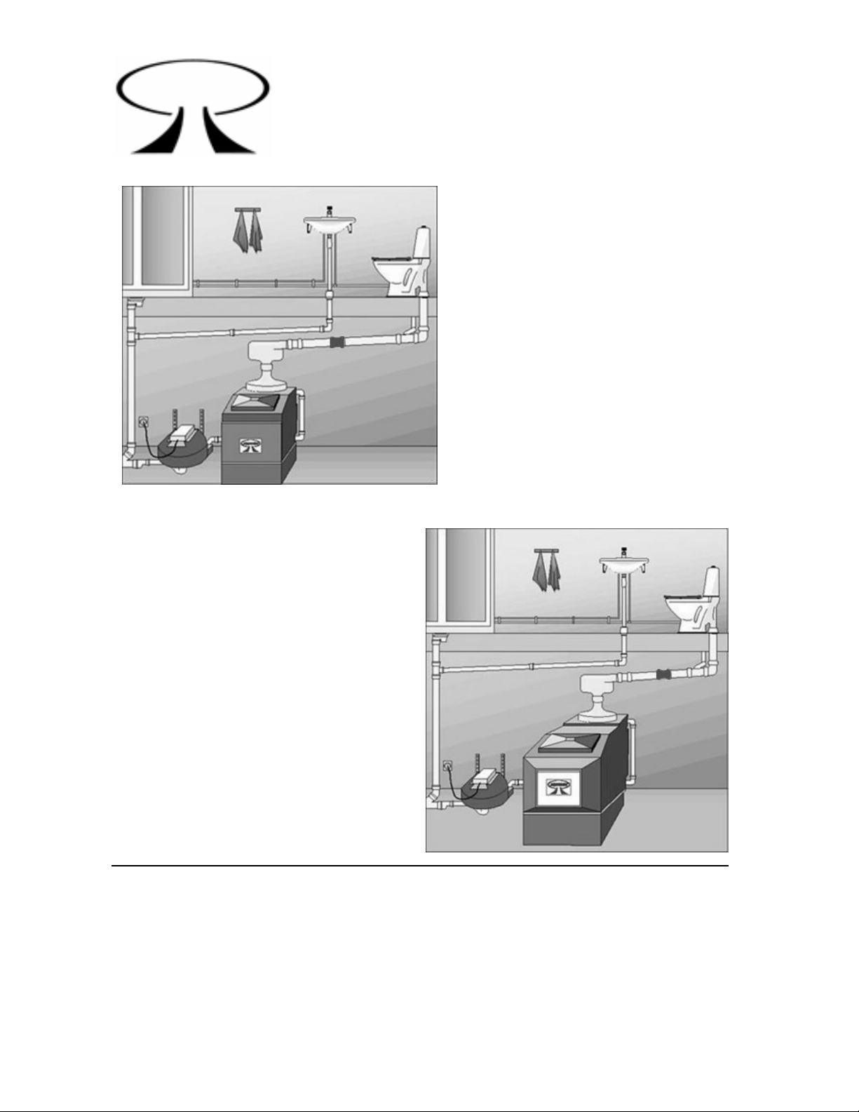
4.3.1 The UV unit should be positioned in such a way that the waste water from the Separator and from
the Bio Chamber can flow freely into the UV unit. It is recommended that the UV unit is placed on
consoles fixed on to the wall, see Figure 4. Make certain that the aluminium lid is positioned in such
a way that it can be easily removed for accessing the UV fixture when replacing burned-out UV light
tubes, for inspection, cleaning the interior of the UV Unit etc.
4.3.2 The UV unit must have its bottom surface horizontally installed.
4.3.3 The 2” Waterseal should be installed underneath the UV unit, see Figure 1, 2 and 4.
4.3.4 The UV unit should be connected to a 230 V grounded outlet.
4.3.5 Germicidal UV-C light tubes are made by:
- PHILIPS, type TUV 15
- OSRAM, type HNS
4.4 Waterseal alternative
If the Aquatron system was ordered without a UV unit, a waterseal must be installed between the branching
pipe outlet and the Grey Water outlet. The waterseal is needed to prevent bad smell from the Grey Water
outlet to enter the toilet system (Bio Chamber). Suggestion for waterseal, see Figure 5.
4.5 Pipe installation
4.5.1 Use 4” pipes between WC and Separator. For ventilation use 3-4” pipes.
4.5.2 The Separator should be connected to a 4” double socket.
NOTE: The Separator must be horizontal and its vertical line (Figure 3) perpendicular to the Bio
Chamber. The inlet pipe must be fully inserted into the socket. See Figure 6.
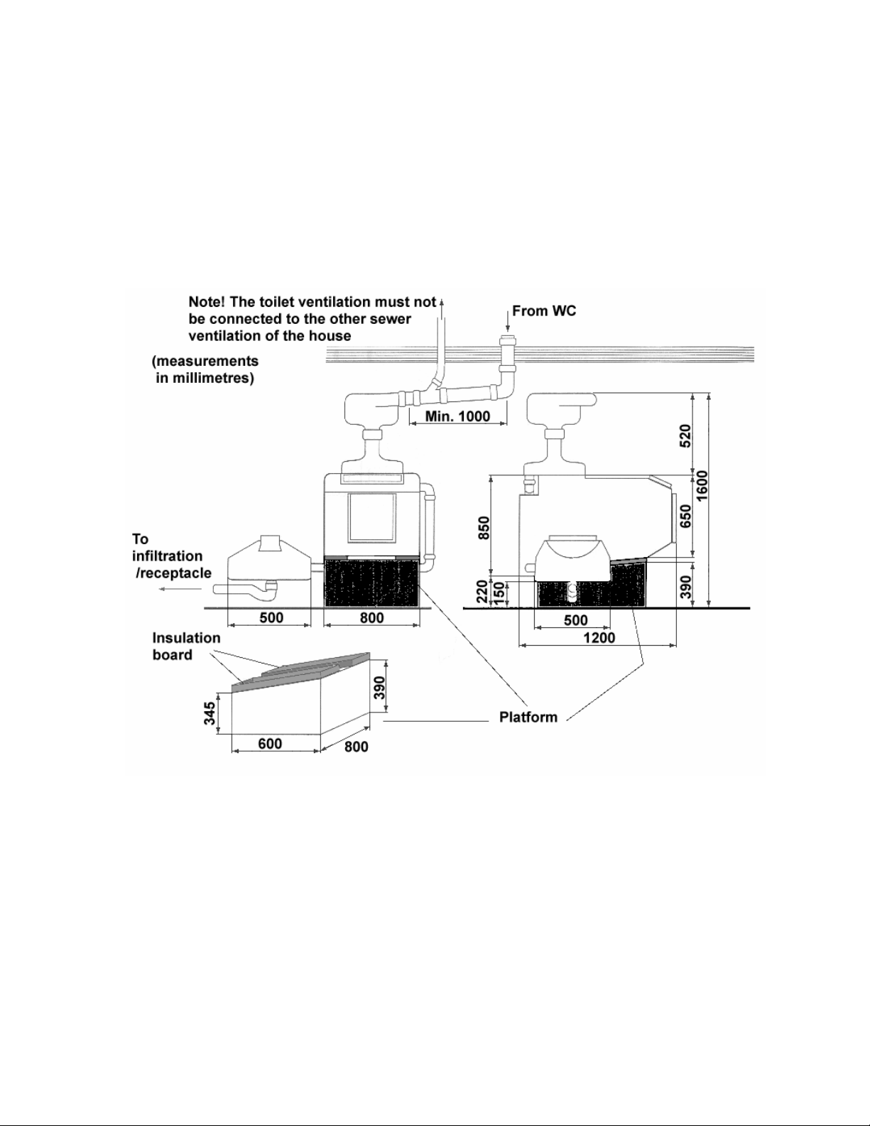
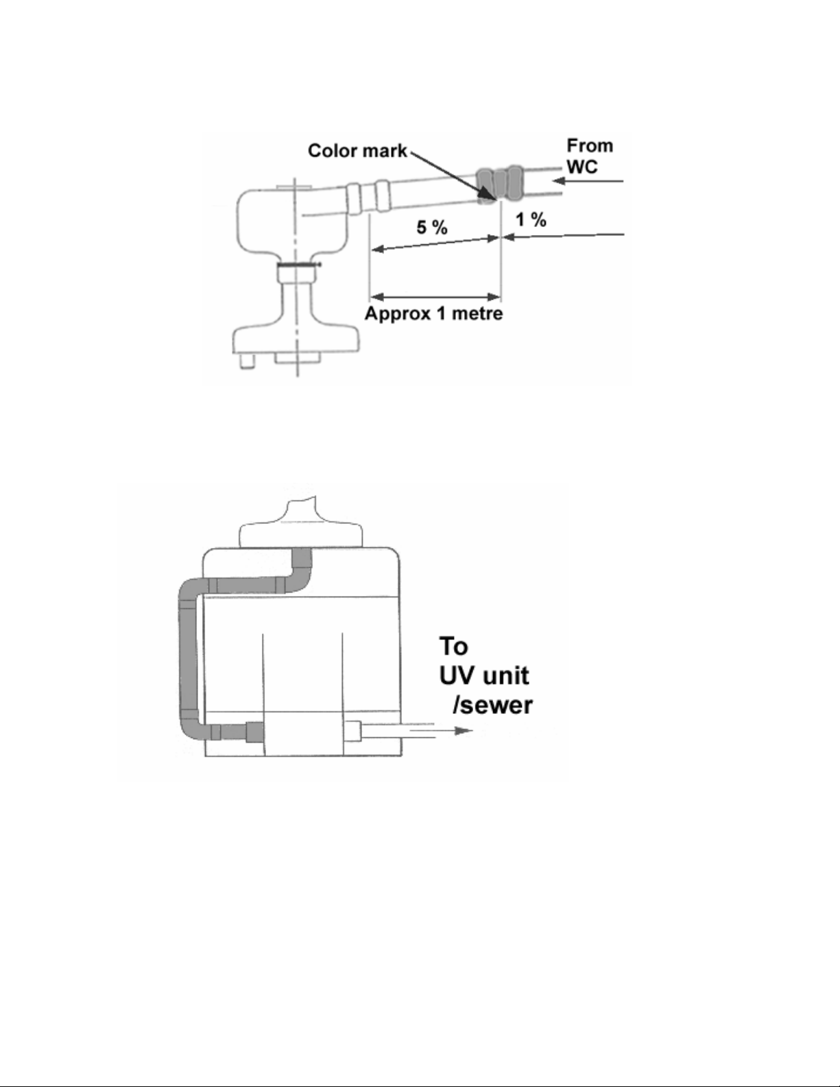
4.5.3 The horizontal distance between the WC and the Separator must be minimum 1 metre and that last
metre (closest to Separator) should be pitched at 5% (5 cm), see Figure 7. At further distances the
earlier part of the pipe should have a 1% horizontal slope, or as national standards. If needed,
use the special angled coupler double socket in order to achieve the pitch transition, see Figure 8.
NOTE: Turn the color mark of the angled coupler double socket downwards. Furthermore, check
that the inclination of the inlet pipe is smooth and that there are no depressions where fluid waste
may gather.
4.5.4 The ventilation should be installed between the WC and the Separator. The ventilation pipe should
extend above the roof.
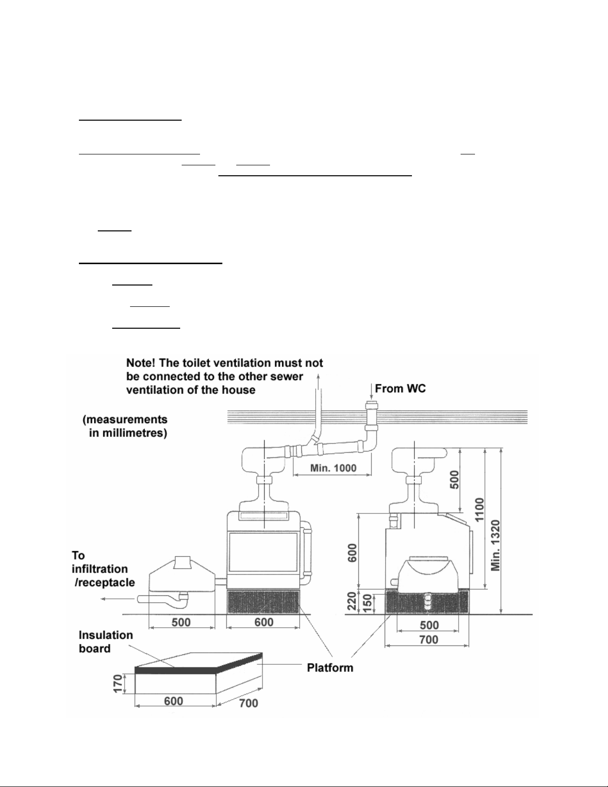
4.5.5 If there is a large level difference between the WC-outlet and the Separator, then first install the
horizontal pipe pitched at the specified angle and then make the necessary level adjustment with the
vertical pipe, see Figure 1 or 2.
4.5.6 The pipe installation from Separator to Bio Chamber and further on to the UV-unit/sewer is shown in
Figure 9. If the UV unit is to be postitioned to the left of the Bio Chamber (as seen from the rear
side in Figure 3), the piping can be reversed. For Aquatron 90, please see text in Figure 9.
4.5.7 If horizontal bends are needed on the Separator inlet pipe, see Figure 10.
4.6 Flushing test
Ask someone to flush the WC with water only and check how much water is entering into the Bio Chamber.
If correctly installed, when flushing with water only, a maximum of 0.5 decilitres should go that way. If too
much water enters into the Bio Chamber there are two explanations:
WARNING! Do not expose your eyes or
skin to direct UV light.
NOTE! Only WC should be connected to the inlet of the Aquatron Separator.
Separate pipes should be used for sewage from bath, kitchen, laundry etc. If
these pipes are to be connected, it should be done after the Aquatron system.
NOTE! Do not use a vacuum-valve. The toilet ventilation must have a separate
vent pipe extending over the roof and must not be connected to the other sewer
ventilation of the house, as this may cause problems with odour and flies.

May 2007
6
4.6.1 If the water enters the Bio Chamber at the beginning of the flushing the velocity of the incoming
fluid is too high and the pitch is too large – decrease the pitch of the inlet pipe.
4.6.2 If the water enters the Bio Chamber at the end of the flushing the velocity of the incoming fluid is
too low and the pitch is too small – increase the pitch of the inlet pipe.
5. COMPOSTING
5.1 Start up
Drainage of the Bio Chamber: Spread a 4-6 centimetres layer of course bark grinds (NOTE: Not peat moss!)
in the Bio Chamber, see Item 7.3 and Item 7.4. The bark grinds should be evenly spread at the bottom of
the Bio Chamber. Make sure that the bottom drain is fully covered by bark grinds by increasing the layer to
10 cm. Add some compost from the garden in order to insert micro-organisms. By this the composting
process will get a more rapid start.
5.2 Vermi composting
See Item 7.5.
6. SPECIAL SOLUTIONS
6.1 Pumping: A pump can be used in order to save approx. 150 mm of required installation height, or
when the grey water sewer outlet level from the house is higher than the fluid outlet from the UV unit,
see Figure 11.
6.2 Urine diversion (Urine sorting/Urine separation): Urine sorting WCs may be connected to Aquatron
toilet systems. Please contact Aquatron International for more information.
Figure 1: Aquatron 90 installation measurements

May 2007 7
Figure 2: Aquatron 400 installation measurements

May 2007
8
Figure 3: Separator installation
Figure 4: UV unit placed on consoles fixed on to the wall

May 2007 9
Figure 5: Suggestion for a waterseal
Figure 6: Connecting Separator and inlet pipe in coupler
double socket
Figure 7: Pitching of inlet pipe from WC to Separator

May 2007
10
Figure 8: Angled double socket for inlet pipes
longer than 1 metre
Connecting pipe and outlet to UV unit/sewer may be reversed. However, for Aquatron 90 where
inlet/outlet on the rear side of the Bio Chamber is placed asymmetrically, the conntecting pipe must
be adjusted and a 50 mm coupler double socket must be acquired and inserted.
Figure 9: Connecting pipe and outlet on rear side of the
Bio Chamber

May 2007 11
Figure 10: Some examples of horizontal pipe bends
The pump installed between the outlet of the Bio Chamber and the inlet of.the UV unit. NOTE! In order to
prevent the fluid to splash on to the UV light tubes and its fitting, a 45°pipe bend must be put on the fluid
inlet on the inside of the UV unit. The pipe bend should be turned towards the bottom of the UV unit. A
reduction between 50 mm and 40 mm diametre should be purchased as well as the 45°pipe bend.
Figure 11: Example of an Aquatron 90 / 400 installed with a
pump

May 2007
12
7. MAINTENANCE INSTRUCTIONS FOR THE AQUATRON 90 / 400 MODELS
7.1 The monitoring of an Aquatron system in use
It is recommended that an Aquatron system in use should be inspected at two week intervals (approximately).
By discovering possible disturbances at an early stage (and to correct them immediately), corrections can be
made more easily as compared to cases where a minor disturbance over time have “built” up to a major
functional disturbance. The Items 7.2 – 7.7 below give advice about checks and measures for such regular
inspections. A special Error Checklist is also included in Item 8.
7.2 Separator
On the top of the Separator is an inspection lid. Occasionally paper may get stuck in the Wire-ring. Open the
lid and push the paper down by using a stick or a small pole. Too soft paper may “felt” too soon and there is
then a risk that it may stick to the wires which may cause too much water to fall into the Bio Chamber. To
avoid this it is recommended that you switch to another type of toilet paper. Depending on water quality (water
containing e.g. high contents of Calcium or Iron) a coating may develop on the wires. If heavily coated,
remove the parts and clean them with a brush.
7.3 Maintenance and drainage of the Bio Chamber
Check regularly the drainage of the Bio Chamber and the consistency of the compost. Also check that the
paper in the Bio Chamber does not build up a pyramid which reaches up to the Separator since that might
cause a stoppage in the Separator. If so, tilt the pyramid with a suitable tool alternatively remove (part of) the
compost. In the Bio Chamber there must be a 4-6 cm layer of bark grinds evenly spread at the bottom and a
10 cm layer extending up and covering the drainage grid (NOTE: important). Add some compost from the
garden in order to insert micro-organisms. By this the composting process will get a more rapid start. It is
important to use coarse bark grinds (NOTE: not peat moss). If it is too smooth it may block the drainage grid
which will cause a wet compost. Suitable material is bark from pine or similar which may be acquired from
garden shops or shops marketing composting products. After using the Aquatron for a couple of years the
drainage layer may have to be renewed.
7.4 Composting
A balance between Carbon and Nitrogen is required for an optimal compost. In a latrine compost the Carbon
comes mainly from the toilet paper and saw-dust (if inserted as sprinkling powder) while the Nitrogen is in
the faeces. In the Aquatron systems a good balance between Carbon/Nitrogen is achieved when using
normal amounts of toilet paper. If the compost, having a correctly installed Separator, still is wet; the reason
might be too little Carbon. Then sprinkle some saw-dust over the compost. The composting compartments
are differently designed:
- Aquatron 90 has a drawer which can be pulled out. The inner wall has a drainage grid through which
excessive fluid is evacuated. The drawer should be emptied into a suitable container for after-
composting or alternatively be replaced by an extra drawer. The filled drawer can then be directly
used for after-composting.
- Aquatron 400 has one single compartment for composting. The inner wall has a drainage grid
through which excessive fluid is evacuated. The compost material will gradually move towards the
emptying hatch and the composting process has then commenced. When needed the compartment
should be emptied and the refuse after-composted in a suitable container.
7.5 Vermi composting
To accelerate the composting process and to effectively reduce the volume (reduction with approx. 90% of
the original volume), earthworms may be added (Eisenia Foetida, also called Dung Worm or Red Wiggler; or
an equivalent specimen). The worms should be added after a couple of weeks of usage.Compost worms can
normally be bought in gardening shops or in stores selling ecological products and equipments. The worms
may also be found in garden compost heaps. The vermi composting process works best at temperatures
between +12 and 25°C. In year-round living a temperature above +15°C is recommended in the
compartment where the Bio Chamber is installed. At temperatures below +10°C the composting process
and the activities of the worms is slowing down and their “food supply” will last longer which may be an
advantage in summer houses which are inhabited for a longer period of time.
7.6 Emptying the Bio Chamber
Remove the compost using a shovel but leave a layer of approx. 5 centimetres thickness. This way you will
leave the drainage layer (bark grinds) in which a major part of the worms stays. If the refuse has not become
fully composted into soil, further composting might be needed.
The Bio Chamber must be installed in a frost free area for the survival of the
compost worms!

May 2007 13
7.7 Changing of UV light tubes in the UV unit
If one UV light tube fails, both tubes should be exchanged for new ones. For further information, see Item
4.3.5. At the same time as the UV unit is opened for replacement of failing UV light tubes it is recommended
that the inside of the UV unit should be cleaned. Check also that there are no sediments in the waterseal
underneath the UV unit. Clean the waterseal if needed.
8. ERROR CHECKLIST
TYPE OF ERROR CAUSE MEASURE
8.1 Wet bio-bed - Bad drainage Check that the drainage holes are not blocked and that
the drainage layer is in accordance with the manual,
see Items 5.1.1 and 7.3.
- Too much water A: Check that the Separator was installed horizontally
in the Bio Chamber and its vertical line perpendicular to the Bio Chamber,
see Figure 3.
B: Check that the Wire-ring is positioned correctly and
that the wires are not crossing each other. The wires
should be slightly bent towards the middle of the
Separator neck, see Figure 3.
C: Check that no paper is stuck in the Wire-ring, see
Item 7.2
D: Check that the cyclone is fully pushed down into the
Separator neck and it rests firmly on the Wire-ring.
See Item 4.2.1 and Figure 3.
E: Check pitch of the inlet pipe. At too large pitch fluid
enters the Bio Chamber at beginning of the flushing,
at too low pitch fluid enters the Bio Chamber at the end
of the flushing. See Item 4.6.
- When flushing there is Check the pitching of the inlet pipe. It must have a smooth
a surge or after flushing slope and no depressions where fluid waste may gather,
there is still a small see Item 4.5.3.
string of fluid or batches
of fluid entering the
Separator
- Leaking WC F: Repair the WC.
8.2 Odour in the room - Wet bio-bed See above.
- Wrong ventilation A: The ventilation pipe is too short, it does not extend
over the roof.
B: The ventilation is coupled together with theother sewer
ventilation of the house. Note: A vacuum-valve must
not
be used.
C: Backflow? See Item 4.1.2.
D: Check the waterseal to assure that no odour is coming
from the sewer system.
8.3 Odour when windy - Air is pressed into The ventilation pipe does not extend high enough above
the ventilation the roof. It must be lengthened. If needed mount a vane
on the ventilation pipe.
8.4 Stoppage in the - A too high pyramid If so, tilt the pyramid using a pitchfork/shovel or remove
Separator has been built up (part of) the compost from the Bio Chamber. See Item 7.3.
in the Bio Chamber
- The wires in the Wire- Straighten the wires.
ring of the Separator
are bent or crossed
WARNING! Do not expose your eyes or skin to direct UV light.

May 2007
14
- The inlet of the Adjust, see Figure 6.
Separator is not fully
inserted into the socket
8.5 Stoppage in the - The flushing water is The pipe between WC and Separator has a too
fluid outlet of entering the Separator large inclination. See Pipe Installation, Items 4.5.3,
the Separator at too high speed 4.5.5 and 4.6.
8.6 Stoppage in the - Sediments or foreign Check that the fluid is not stopped in the UV unit or
fluid outlet of the objects in the fluid in the waterseal underneath it. Clean the UV unit and
system outlet the waterseal from sediments and foreign objects.
8.7 Flies in the - Wet bio-bed See Item 8.1 and 8.2 above.
Bio Chamber
Spray the inside of the Bio Chamber with an
appropriate insecticide. Check the mosquitionet
at the top of the vent pipe.
This manual suits for next models
1
Table of contents