aquilar EcoLeak Eco-6 User manual

Eco-6
Six Zone Panel
EcoLeak
INSTALLATION
INSTRUCTIONS

ECO-6
100 to 240 Vac, 50-60 Hz,
POWER CONSUMPTION
5 watts
RELAYS
Number: Twa for leak relay and one for cable
break / power failure.
Type: SPDT
Rating: 3 A at 250Vac/24 Vdc
SENSING CABLE COMPATIBILITY
All EcoLeak and TraceTek sensing cable
(TT1000, 1100, 3000, 5000, series)
PROBE COMPATABILITY
All EcoLeak, Aquitron Probes
DETECTION PROBES
1 x EL-MPS-R or 4 x AT-PROBE per zone
INSTALLATION ITEMS
(NOT SUPPLIED)
• Wall fasteners for surface mounting (four
screws)
• Rubber or elastomeric washers to seal
at mounting points
TOOLS REQUIRED
• Drill or hole punch for electrical
conduit entries
• Phillips (cross-head) screwdriver
• Small at-head screwdriver
STORAGE
Keep the module in a dry place prior to
installation to avoid possible damage to
internal components.
MAXIMUM LENGTH OF SENSING
CABLE
30 metres per zone
MAXIMUM LENGTH OF LEADER
CABLE
300 metres per zone
NUMBER OF ZONES
6
SENSING CIRCUIT
2 and 4 wire sensing
CABLE ENTRY
20mm dia, 6 along the bottom, 8 on the back,
1 on right side. Appropriate stung glands
should be used.
DIMENSIONS AND WEIGHT
226 x 206 x 70, WxHxD. 1.85kg
WORKING TEMPERATURE RANGE
5°C to 40°C
Please read these
instructions carefully
and keep them in a
safe place (preferably
close to the module) for
future reference. These
instructions must be
followed carefully to ensure
proper operation.Wiring of
this alarm panel should be
carried out by a suitably
qualified technician in
accordance with the
applicable regulations and
standards in the relevant
industry/country. This
manual is intended as a
guide, and Aquilar Ltd
bears no responsibility
for damage or injury
arising from incorrect
installation of this and any
supplementary equipment.
A. GENERAL INFORMATION
The Eco-6 alarm panel is designed for use with all AquiTron and TraceTek sensing cables and
sensors for detection of water, acid, hydrocarbon liquids (fuels) and refrigerant gas leaks.
Including built in battery back up as standard, while monitoring for both leak and cable break
on up to six separate zones. The Eco-6 is a truly versatile leak alarm panel.
B. PRODUCT INFORMATION
LEAK DETECTION SOLUTIONS
Eco
L
eak
Weights & Measures House, 20 Barttelot Road,
Horsham, West Sussex RH12 1DQ
+44 (0) 1403 216100
www.aquilar.co.uk
1
Eco-6
Six Zone Panel

Eco-6
Six Zone Panel
LEAK DETECTION SOLUTIONS
Eco
L
eak
Weights & Measures House, 20 Barttelot Road,
Horsham, West Sussex RH12 1DQ
+44 (0) 1403 216100
www.aquilar.co.uk
2
ENCLOSURE
Powder coated steel, colour RAL 9006 matt,
lockable, IP43 - Indoor use only
WORKING HUMIDITY RANGE
5% to 80% non-condensing
STATUS LED
Power Mains-Green, Leak-Red, Cable break-
Yellow
AUDIBLE ALARM
90dB at 10cm
BATTERY BACK-UP
24 hours, integral 6Vdc, 1850mA battery
APPROVALS
BS EN 61000-6-1 2007 Electromagnetic
compatibility (EMC). Generic standards.
Immunity for residential, commercial and
light-industrial environments.
BS EN 61000-6-3 Electromagnetic
compatibility (EMC) Generic standards.
Emission standard for residential,
commercial and light-industrial
environments.
2006/95/EC The Low Voltage Directive
2004/108/EC The Electromagnetic
Compatibility Directive
2011/65/EU The Restriction of Hazardous
Substances Directive
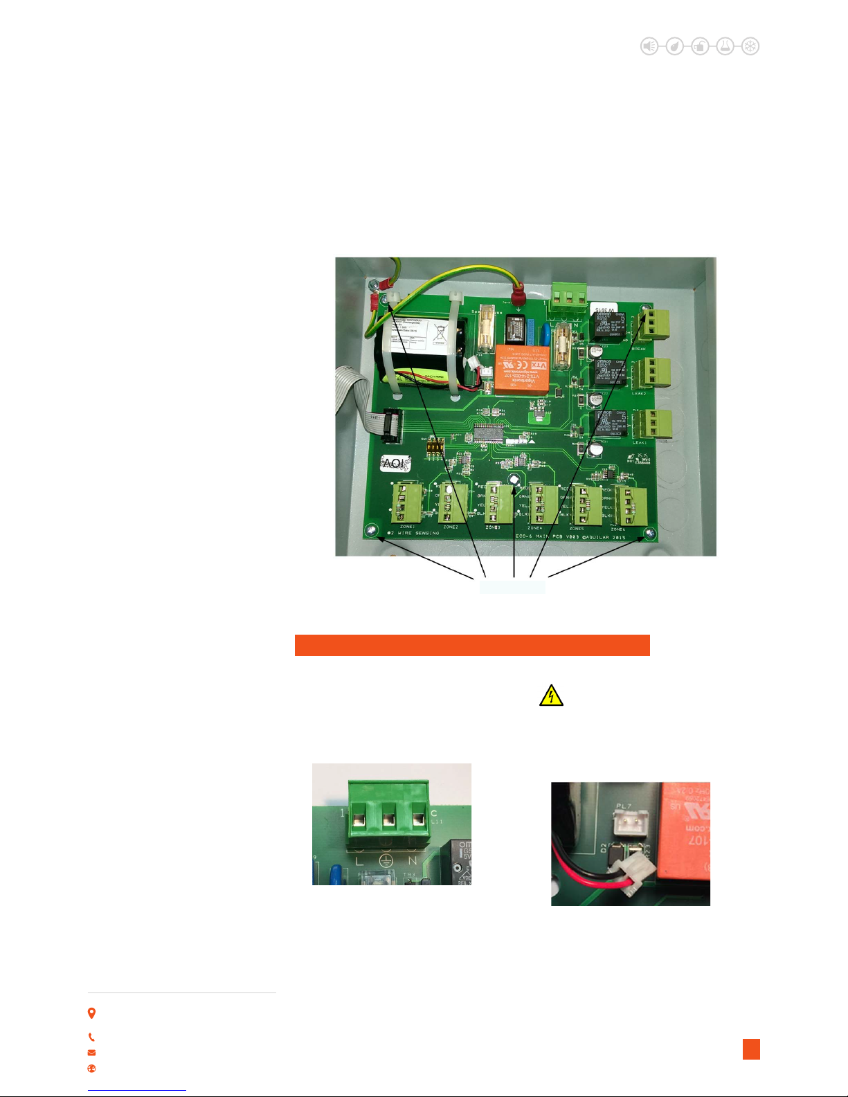
C. ALARM PANEL MOUNTING
The Eco-6 leak alarm panel should be mounted on an internal at surface away from direct
contact with water.3 x xing holes are provided along with several 20mm diameter knockouts.
To access the xing holes it is recommended the circuit board is removed prior to mounting
and any holes knocked out/drilled for conduit being tted. To remove the circuit board the
door board ribbon cable connector and earth bond lug should be carefully unplugged from the
circuit board rst.
LEAK DETECTION SOLUTIONS
Weights & Measures House, 20 Barttelot Road,
Horsham, West Sussex RH12 1DQ
+44 (0) 1403 216100
www.aquilar.co.uk
3
Eco-6
Six Zone Panel
Eco
L
eak
Remove the ve xing screws retaining the board. Carefully remove the circuit board and
keep safe. Once the enclosure has been xed, ret circuit board taking care not to overtighten
screws. The earth lug and door board ribbon cable must also be retted for correct operation
of this device.
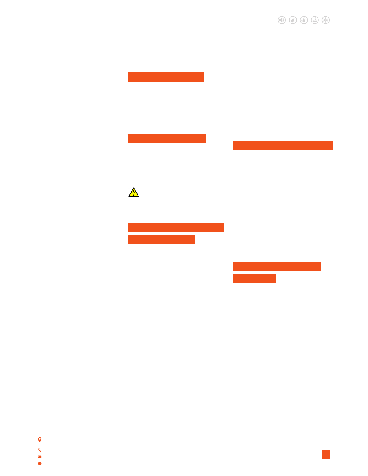
D. MAINS POWER AND BATTERY CONNECTION
It is recommended this alarm panel should
be connected to 230Vac mains power via an
un-switched 3A fused spur. The panel has the
capability to be connected to 110 – 240Vac.
Mains power must be isolated prior to any
connection being made or altered.
This alarm panel MUST be earthed.
Warning Shock Hazard. Exposed
Circuitry within! It is strongly
recommended the power is isolated before
opening the control panel lid and carrying out
any work within the unit.
Ensure the battery pack is plugged in. Allow
24 hours for full charge. While the panel is in
use this should be left connected at all times.
5 x Fixing Screws

Eco-6
Six Zone Panel
LEAK DETECTION SOLUTIONS
Eco
L
eak
Weights & Measures House, 20 Barttelot Road,
Horsham, West Sussex RH12 1DQ
+44 (0) 1403 216100
www.aquilar.co.uk
4
E. IMPORTANT SENSOR
INFORMATION
TWO WIRE SENSING: ECOLEAK
SENSING CABLE, ECOLEAK PROBES
Two wire systems should be connected
using the red-black outer terminals only. As
indicated by the white dots. Use only Aquilar
EcoLeak cable or Aquilar probes for two wire
sensing. Use of other sensing devices could
cause the panel to malfunction.
EcoLeak sensing cable is not extendable. If
sensing is required in more than one area
on each zone, TT1000 should be used with
AT-MJC/AT-BJC jumper cable between the
sensing areas (up to a maximum of 30m total
sensing cable per zone).
FOUR WIRE SENSING: TT1000,
TT1100, TT5000, AT-PROBE ETC.
When using four wire system with Aquilar
AT-MLC leader cable or AT-BJC jumper cable
the red-green and yellow-black colour coding
on the zone sensor input terminals should be
observed.
NOTE: Do not connect more than one
sensing circuit into the Eco-6. Doing so
will cause malfunction in the cable break
checking system and may prevent the
panel from detecting cable faults and
leaks.
Any unused zones must be linked out at
the panel as shown, or an 82KΩ resistor
tted between the dotted terminals (red
and black). Failure to do this will cause the
panel to show a cable fault on that zone.
F. RELAY CONNECTIONS
Three volt free relays are available for
connection to external equipment. The
relays have common, normally open and
normally closed contacts. All relays are volt
free contacts. No power is available from
them. If using them to control equipment that
requires power, an external power source
must be supplied (by others) and the relay
used as a switch. Please see relay connection
addendum at the end of this manual for
further connection guidance. The relays
are rated for a maximum load of 5A 250V.
Exceeding this may cause irreparable damage
to the alarm panel.
Warning Shock Hazard! Caution 230V
mains voltage could be present at
these relays that may require isolation
elsewhere.
Leak 1 and Leak 2 relays both operate when
a leak is detected within any of the six zones
and the leak alarm is in operation.
The break relay operates when a cable break
is detected on any of the six zones or power
is lost to the panel. (Note: if the integral
battery pack is plugged in and charged the
system will continue to monitor for leaks and
cable break for a minimum 24hrs until the
backup battery discharges).

Eco-6
Six Zone Panel
LEAK DETECTION SOLUTIONS
Eco
L
eak
Weights & Measures House, 20 Barttelot Road,
Horsham, West Sussex RH12 1DQ
+44 (0) 1403 216100
www.aquilar.co.uk
5
All relays will only reset when the leak/fault
has been rectied and the reset button is
operated. Mute has no eect on relay output.
IMPORTANT! Relay output terminals refer
to the panel in its ‘o’ state. The Break/Fault
relay is energized when the panel is mains
powered. Once power is applied to the panel
the normally open and closed terminals are
reversed.
G. NORMAL OPERATION
After connections are complete, supply
power to the unit. If the sensing circuit is
complete and free of leaks or other problems,
the panel will run a function test and then
the green mains power LED only will remain
illuminated.
After connections are complete, supply
power to the unit. If the sensing circuit is
complete and free of leaks or other problems,
the panel will run a function test and then
the green mains power LED only will remain
illuminated.
Testing the alarm panel after supplying
power and Routine maintenance
procedure:
• When power is supplied, the GREEN LED
illuminates for mains power.
• Place water or a mapping tool on the
probe or sensing cable and the Eco-1 panel
should report an alarm condition. For the
TraceTek TT5000 systems, simulate a leak
condition by tightly bending and holding
the sensorcable. Please refer to relevant
TraceTek datasheet.
• Verify that the RED alarm LED is illuminated.
• Conrm the Leak relay operates.
• The buzzer will sound and will only be
silenced when the mute button is pressed
or system is reset. Reset is onlypossible
once the probe or sensing cables are dried.
• To test the fault alarm operation disconnect
the probe or sensing cable from the leader/
jumper cable. The Eco-6 panel will report a
fault alarm.
• Verify the YELLOW alarm LED is illuminated
• Conrm fault relay operates.
• Buzzer mute and reset in same method as
for a leak alarm. Reset is only possible once
the fault has been repaired.
• Turn o mains power (after allowing
sucient time for battery charge). Green
power light will go out, Red battery
• LED will illuminate to indicate panel is
running on battery power. If battery LED
is ashing or does not illuminate battery
power is too low for proper operation and
will require further charging.
• While on battery power ensure leak and
fault functions operate correctly.
If the Eco-6 unit still does not appear to
operate properly contact your supplier for
assistance.
H. RESETTING THE UNIT
When the probe or sensing cables are dried
or repaired press the reset button. The unit is
designed so an alarm can be muted, but the
panel cannot be reset until the leak or fault
has been rectied. If auto reset is enabled the
system will still not reset until the leak/fault
has been rectied.
Eco-6
Six Zone Panel
LEAK DETECTION SOLUTIONS
Eco
L
eak
Weights & Measures House, 20 Barttelot Road,
Horsham, West Sussex RH12 1DQ
+44 (0) 1403 216100
www.aquilar.co.uk
6
I. CLEANING THE UNIT
If it is necessary to clean the outside surface,
use a dry cloth or sponge. Do not use
solvents or abrasive cleaners. Do not open
the enclosure if it is wet (risk of electrical
shock).
J. FUSE REPLACEMENT
The panels mains input is protected by a
T500mA, 250-V fuse. Use no other type of
fuse or the Eco-6 panel could be damaged or
could fail to perform properly.
Warning Shock Hazard. Exposed
Circuitry within! It is strongly
recommended the power is isolated before
carrying out any work within the unit.
K. STORAGE AND HANDLING
OF SENSING CABLE
Despite their rugged construction, EcoLeak
and TraceTek sensing cables must be handled
in a manner appropriate for a sensing
device or they may be damaged and require
replacement.Therefore, you should follow
some basic rules for storing and handling all
sensing cables:
• Store spare cable in its original packaging
or container in a clean, dry place until ready
for installation.
• Schedule cable and probe/sensor
installation after all mechanical, plumbing,
and electrical work has been completed
• Clean the area where the cable is to be
installed, and remove any obvious debris or
other sources of contamination.
• Do not solder or weld near the cable
without providing protection from heat,
solder ux, or weld splatter.
• Do not drop tools or oor tiles on the cable;
sharp and heavy objects may damage the
cable.
• Avoid walking or stepping on the cable.
Provide shielding (for example, a half shell
• of plastic pipe or upturned cable tray) where
additional protection is necessary.
• Do not use insulation tape or similar to
secure sensing cable (some tapes and
adhesives absorb moisture) or use solvents
that could eventually cause an alarm.
• Do not drag sensing cable through
contaminants (such as pipe ux, PVC
cement, solvents, oil, water or dirt)
L. NOTE ON CABLE CLEANING
EcoLeak and TraceTek sensing cables use
a solid core polymer construction and can
usually be easily cleaned with tap water. In
extreme cases or when large amounts of
cable are contaminated, either cable can
be washed in a dishwasher. Try a water
only (no detergent) cycle rst and avoid the
heated dry cycle. When placing the cable in
the dishwasher be sure to keep water out of
the connectors (TraceTek cable ends can be
connected together for convenience).
The TraceTek TT5000 sensing cables cannot
be cleaned and must be replaced after
exposure to fuel or solvent.
K. FINAL COMMISSIONING
CHECK LIST
1. Complete a system inspection in the
presence of the owner.
2. Ensure a plan showing the location of the
zone and sensor is available.
3. Check that the following information
is clearly visible adjacent to the alarm
module:
• “In case of alarm” instruction.
• Location of the system “as tted
drawing” in case it is not installed adjacent
to the alarm module.
• Name and contact number of the person
responsible for operating the system
• Supplier’s contact name and address.
Or details of the installation/maintenance
company.
4. Hand over these Installation, Operating
and Maintenance Instructions.

Eco-6
Six Zone Panel
LEAK DETECTION SOLUTIONS
Eco
L
eak
Weights & Measures House, 20 Barttelot Road,
Horsham, West Sussex RH12 1DQ
+44 (0) 1403 216100
www.aquilar.co.uk
7
5. Make the owner aware that it is strongly
recommended to perform a systems check
at regular intervals, as a minimum once
every 12 months.
M. ROUTINE MAINTENANCE
AND TESTING
Perform a functional check per the following
procedure as a minimum of 12-month
intervals. Repair or replace all damaged
wiring, probes and sensor cables. Such a
check will identify conditions that adversely
aect the capability of the system.
More frequent checks may be required if the
sensing cable is repeatedly exposed to leaks,
or if construction or repair work is done
where the sensing cable or probes may be
exposed. Apart from fuse replacement there
N. ROUTINE TEST
PROCEDURE:
• Should be carried out as initial setup
procedure as set out above.
• Important Note: This may cause external
equipment to shut down or go into alarm if
devices are connected to the leak and fault
relay contacts.
are no eld repair procedures for the Eco-6
panel. If the module fails to perform the
functional tests it must be returned to your
supplier for repair or replacement.
Contact your local EcoLeak representative
for further information on service and
maintenance support.
N. TROUBLESHOOTING
POWER
Problem:
Green mains power LED Does not illuminate
Possible Cause:
No power to alarm panel. Mains or internal
fuse blown.
Action:
Check 3A fuse within spur, replace if
necessary. Verify mains power present at
mains terminals of panel. Check internal
T500mA fuse, replace if necessary. If panel
remains inoperative please contact supplier.
Problem:
Red battery power LED does not illuminate,
or ashing when mains power removed.
Possible Cause:
Battery pack not plugged in. Battery not
charged
Action:
Plug battery pack into connector PL7 and
leave with mains power on for minimum
24hrs.
Problem:
Red battery power LED fails to illuminate or
continues to ash after 24hrs charging.
Possible Cause:
Faulty battery pack.
Action: Contact supplier for replacement.
RELAY OUTPUTS
Problem:
No power from the relay
Possible Cause:
Relays are volt free contacts. No power is
available from them.
Action:
Rewire to use relay as a switch from an
external power source. Please see relay
connection addendum.
Problem:
Solenoid valve opening when expected to
be closed (or vica versa), or other connected
equipment behaving in the opposite manner
to required. Paying particular attention to the
break/fault relay as it is energized when the
alarm is powered.
Possible Cause:
Cable is pinched (all cables).
Action:
Use other terminal. Please see relay
connection addendum.

Eco-6
Single Zone Panel
LEAK DETECTION SOLUTIONS
Eco
L
eak
Weights & Measures House, 20 Barttelot Road,
Horsham, West Sussex RH12 1DQ
+44 (0) 1403 216100
www.aquilar.co.uk
WATER SENSING
Problem:
Leak Alarm, but no leak is found.
Possible Cause:
Sensing cable is dirty or contaminated.
Action:
Clean cable using water (no solvents, acetone,
white spirit or turps). Dry the cable and check
Eco-Leak front panel. Heavily contaminated
cable may require replacement. But if dirt is
accumulating, cleaning and/or replacement
will eventually be required.
Problem:
Leak Alarm, but no leak is found.
Possible Cause:
Sensing cable is exposed to occasional water
spraying.
Action:
It is best to keep the sensor cable at least
1 meter (3 feet) from the airow of any air
conditioning units, or areas where occasional
wetting of the sensor could be expected.
Problem:
Leak Alarm, but no leak is found.
Possible Cause:
Cable is in contact with sharp metal edges.
Action:
Check the sensor cable for possible points of
contact with sharp edges such as the edges of
drip trays or the pipe threads on adjustable
oor supports trunking and ducting.
Reposition the cable as necessary or insert a
small piece of insulating material to prevent
the cable from making contact with the metal
edge.
FUEL OIL SENSING
Problem:
Leak Alarm, but no leak is found.
Possible Cause:
Cable is pinched (TT5000 cable)
Action:
Check the sensor cable for possible pinch
points. TT5000 can indicate a leak if tightly
bent or compressed by a heavy object
8
Problem:
Leak Alarm.
Possible Cause:
Probe or sensing cable is contaminated
(TT5000 cable)
Action:
Locate the spill area, investigate the cause of
the spill and take necessary repair actions.
Clean up in the spill area and clean and dry
the probe, if necessary. Any TT5000 cable
contaminated with hydrocarbons (oil, fuel
etc.) will need to be replaced, it cannot be
cleaned and re-used. Leak LED will turn o
when cable/probe is replaced/dried and reset
button is pressed.
FAULT ALARM
Problem:
Fault output to BMS but no fault indicated on
zones (Battery LED illuminated).
Possible Cause:
Mains power lost to panel.
Action:
Check mains power is connected and
turned on. Check fuses. Test and replace as
necessary.
Problem:
Fault indicated, but no obvious fault found.
Possible Cause:
Loose connection on sensing circuit.
Action:
Check all connections are suciently
tightened within the alarm panel, connectors
are fully pressed home, and any modular
connectors are fully tightened. If using
TT1000 sensing cable or AT-PROBE-M ensure
the TT-MET-PC end termination is tted
properly on the end of line. If using AT-
PROBE-TS ensure the last probe has end of
line terminations (cable loops) tted.
Problem:
Fault indicated, but no obvious fault found.
Possible Cause:
Sensing cable or probe faulty or damaged.
Action:
Check sensors for damage, test and replace
as necessary.

Eco-6
Six Zone Panel
LEAK DETECTION SOLUTIONS
Eco
L
eak
Weights & Measures House, 20 Barttelot Road,
Horsham, West Sussex RH12 1DQ
+44 (0) 1403 216100
www.aquilar.co.uk
9
Problem:
Fault indicated, but no obvious fault found.
Possible Cause:
Short to earth on sensing circuit.
Action:
Check sensing cables or probes are not
earthed. Pins on probes should be positioned
not touching metal surfaces. Sensing cable
not positioned running over sharp metal
surfaces (drip tray edges, false oor support
pedestals etc.)
Important: All information, including illustrations, is believed to be reliable. Users, however,
should independently evaluate the suitability of each product for their application. Aquilar
Limited makes no warranty as to the accuracy or completeness of the information, and
disclaims any liability regarding its use. The only obligations of Aquilar Limited are those in
the Aquilar Standard Terms and Conditions of Sale for this product, and in no case will Aquilar
Limited be liable for any incidental, indirect, or consequential damages arising from the sale,
resale, use or misuse of the product. Specications are subject to change without notice. In
addition, Aquilar Limited reserves the right to make changes – without notication to Buyer
– to processing or materials that do not aect compliance with any applicable specication.
AquiTron, EcoLeak are trademarks of Aquilar Limited.
V1 05.2017
Table of contents
Popular Control Panel manuals by other brands


Biamp
Biamp TEC-X 1000 Installation & operation guide

auto maskin
auto maskin Marine Pro 200E Series Configuration manual

Junkers
Junkers TR 100 instruction manual

Haes
Haes ESG-2001 Installation, commissioning & operating manual

SAINT-GOBAIN
SAINT-GOBAIN SageGlas 300-1176-001 Product sheet

Ampac
Ampac ZoneSense Plus Operation & programming manual


