auto maskin Marine Pro 200E Series Instruction sheet

Manual# 1006496
Configuration Manual
200E Series
DCU 210E/208E –Engine Panel
RP 210E/220E –Remote Panel
Configuration Manual - 200E Series
Page ii
Configuration Manual
for the
Marine Pro 200E Series
~~~
DCU 210E/208E Diesel Engine Control Unit
RP 210E/220E Remote Panel
Revision
1.3
Revised
January 23, 2017
Revision history:
Rev.
Date
Description
1.0
15.10.2015
Release
1.1
18.03.2016
Firmware update
1.2
25.11.2016
Added RP 220E
1.3
22.01.2017
Synched to firmware 3.5P2
Copyright © 2017 by Auto-Maskin AS.
All rights reserved. No part of this document may be reproduced or transmitted in any form or by any means,
electronic, mechanical, photocopying, recording, or otherwise, without the prior written permission of Auto-Maskin AS.

Configuration Manual - 200E Series
Page iii
Table of Content
DOCUMENT INFORMATION ................................ 1
ABOUT THIS MANUAL .............................................. 1
Responsibilities .............................................. 1
MATCHING FIRMWARE ............................................ 1
ORDERING INFORMATION......................................... 1
OVERVIEW OF THE 200 SERIES .................................. 2
DCU 210E Engine Panel ................................. 2
DCU 208E Engine Panel ................................. 2
Configuration................................................. 2
RP 210E/220E Remote Panel......................... 2
Ethernet Switch ............................................. 3
Expansion ...................................................... 3
FIRST POWER-ON................................................... 4
Preparations .................................................. 4
First Power-On Wizard .................................. 4
CONFIGURATION................................................. 5
CONFIGURATION-AND FIRMWARE FILES...................... 5
DCU Web Server Configuration Interface ...... 5
USB memory with Configuration file ............. 5
Connecting to the DCU .................................. 5
Further connection settings........................... 6
Logged in ....................................................... 7
DCU................................................................ 7
RIO................................................................. 8
SDU................................................................ 8
Upload Wallpaper ......................................... 8
Versions ......................................................... 8
Troubleshooting ............................................ 8
MAIN DCU WEB SERVER MENU................................. 9
Password ....................................................... 9
File ................................................................. 9
I/O CONFIGURATION ............................................ 10
Flexible I/O................................................... 10
Config Inputs ............................................... 10
Config Outputs............................................. 21
USER INTERFACE ................................................25
CONFIGURATION .................................................. 25
Header......................................................... 25
Instruments ................................................. 25
PAGES ................................................................ 25
Page details ................................................. 25
Apply a signal to a slot ................................ 26
Edit a signal ................................................. 26
Insert a new Page ........................................ 26
Choose a Template ...................................... 26
Delete a Page .............................................. 26
FLOW CHARTS...................................................... 26
RP HOME VIEW CONFIGURATION............................ 27
CONTROLS........................................................... 27
Gear............................................................. 27
SHORTCUTS ......................................................... 27
LANGUAGE .......................................................... 27
BUZZER............................................................... 28
START/STOP/ PRELUBE...................................... 29
PRELUBE ............................................................. 29
Prelube –Fixed Time.................................... 29
Prelube –Until Pressure .............................. 29
Oscillating.................................................... 29
DCU ENGINE START/STOP CONTROL ....................... 30
AUTOMATIC START ............................................... 30
STARTER 1........................................................... 30
STARTER 2........................................................... 30
AUTOMATIC STOP................................................. 31
START/STOP BUTTONS .......................................... 31
Latched buttons........................................... 31
Momentary buttons .................................... 31
E-Start.......................................................... 31
USER INTERFACE................................................... 32
Language..................................................... 32
Buzzer .......................................................... 32
ENGINE MODEL.................................................... 33
Engine Name ............................................... 33
SERVICE INTERVAL ................................................ 33
View Service Status...................................... 33
Configure ..................................................... 33
COMMUNICATION ................................................ 33
Network Communication............................. 34
Modbus RTU ................................................ 34

Configuration Manual - 200E Series
Page iv
Modbus TCP................................................. 34
J1939 Configuration .................................... 34
MISCELLANEOUS .................................................. 35
Alarm Configuration .................................... 35
Counters ...................................................... 35
Acknowledge Configuration ........................ 36
Event Log ..................................................... 36
Suppress DM1 faults.................................... 36
Engine Application Configuration................ 36
System Voltage............................................ 37
Factory Reset ............................................... 37
RP CONFIGURATION...........................................38
POWER-ON WIZARD............................................. 38
ADMINISTRATION MENU........................................ 39
DCU Connection / Connections.................... 39
DCU Alarms ................................................. 39
DCU Acknowledge ....................................... 39
IP Address .................................................... 40
Cameras....................................................... 40
Station Location........................................... 40
Functional Inputs......................................... 40
Change Password ........................................ 41
Station priority............................................. 42
Lock.............................................................. 42
System Voltage............................................ 42
Reset to Factory Default.............................. 43
Configuration Manual - 200E Series
Page 1
Document
Information
About this manual
This manual has been published
primarily for professionals and
qualified personnel.
The user of this material is assumed to
have basic knowledge in marine
systems, and must be able to carry out
related electrical work.
Warning!
Work on the low-voltage circuit should
only be carried out by qualified and
experienced personnel.
Installation or work on the shore
power equipment
must only
be carried
out by electricians authorized to work
with such installations.
Responsibilities
Warning!
It is the
sole responsibility of the
installer
to ensure that the installation
work is carried out in a satisfactorily
manner, that it is operationally in good
order, that the approved material and
accessories are used and that the
installation meet all applicable rules
and regulations.
Note! Auto-Maskin continuously
upgrades its products and reserves the
right to make changes and
improvements without prior notice.
All information in this manual is based
upon information at the time of
printing.
For updated information, please
contact your local distributor.
Matching firmware
This Configuration Manual is for the
200E Series of panels.
It has been updated to match the
following firmware releases.
Panel
Firmw.
Release
DCU 210E/ 208E
3.5 P2
January 2017
RP 210E/RP 220E
3.5 P2
January 2017
Ordering information
The Marine Pro covers a wide range of
compatible products within both the
200- and 400 Series. Please visit our
web site for more information.
http://auto-maskin.com/marine/
Configuration Manual - 200E Series
Page 2
Overview of the 200
series
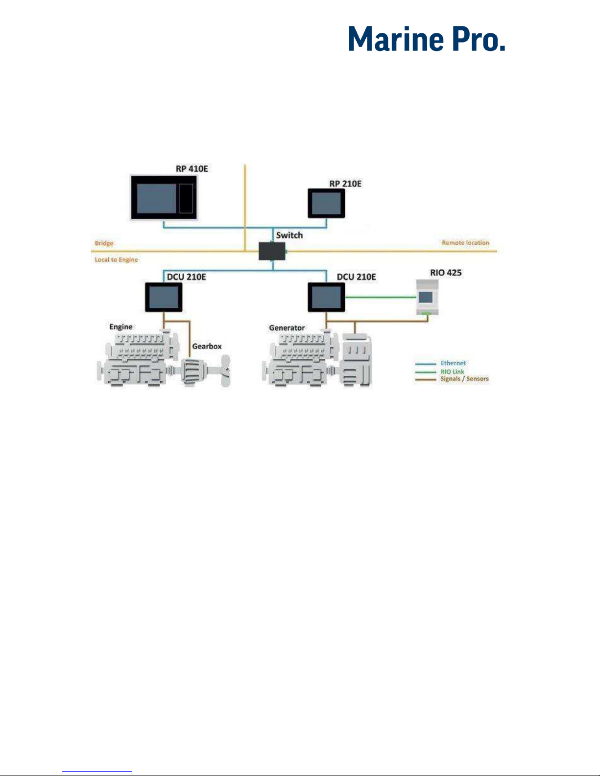
The drawing below shows a typical
layout.
DCU 210E Engine Panel
The DCU 210E engine panel is the
main building block in the 200 Series.
Engine sensor values are displayed on
the color touch screen, and commands
and other user interaction is also here.
DCU 208E Engine Panel
The DCU 208E is basically the same as
the DCU 210E, but without the color
touch screen.
It saves cost being used in smaller
engine rooms, where a remote panel is
all that is needed.
Configuration
An ordinary PC web-browser is used
to configure the DCU, using the inbuilt
web-server on the DCU.
RP 210E/220E Remote Panel
The optional RP remote panel brings
everything on the DCU to a remote
location, with the exact same user
interface. It does not need any
configuration, as it is reading the
configuration from the DCU.
As such, the RP can easily be
retrofitted.
The RP also supports one IP-camera to
be installed on the network.

Configuration Manual - 200E Series
Page 3
Ethernet Switch
The Ethernet switch is not necessary if
only one DCU 210E and one RP
210E/220E is in use. These can then
be wired with an Ethernet cable
directly.
It is recommended to make use of an
Ethernet switch though, as it simplifies
PC configuration connection and
future expansion to remote panels
and/or camera interface.
Expansion
The basic system can be expanded
with more input and output channels
using the versatile RIO units (Remote
I/O).
Currently, there are RIO units for
General I/O expansion, RIO 410
and RIO 210.
Exhaust temperature
monitoring, RIO 412
Generator monitoring, RIO 425
Load sharing, LSU 408

Configuration Manual - 200E Series
Page 4
First Power-On
Preparations
First, make sure to consult the Quick
Installation Guide (QIG) that came with
the panel.
Installation
Install the panel according to
guidelines in the Installation manual.
Connections
Connect power to the panel according
to guidelines in the Installation
manual.
First Power-On Wizard
The DCU (not DCU 208E) will display
the
first power-on wizard
at the first
power up after delivery, or after a
factory reset of the panel.
All wizard settings can be changed
later.

Configuration Manual - 200E Series
Page 5
Configuration
This section explains the configuration
of the DCU.
Configuration- and
Firmware files
The DCU may be configured either
using the built in web server, or by
inserting a USB memory stick with a
predefined configuration file.
DCU Web Server Configuration
Interface
The panel has a built in web server,
offering access to full configuration.
USB memory with Configuration
file
Insert a USB memory with the
configuration file(s) and follow the
guidelines appearing on the panel
screen.
Valid filename characters
a-z
A-Z
0-9
“_” (underscore)
“-“(hyphen)
If other characters are being used,
then the panel may not “see” it.
Rename the configuration file to solve
the issue.
When the USB memory is inserted, the
panel asks for the administration
password (4 digits).
The panel then lists the configuration
file(s) available on the USB memory.
Select file(s) then select COPY to copy
these files into the User Files area in
the panel. Note that this does not
activate the file; it is merely a copy of
the file into the panel.
Select a file, and then select USE to
copy and activate this configuration
file.
Note! The DCU 208E does not have a
screen interface and hence this
method does not work on that unit.
USB memory with Firmware
file
A USB memory stick can be used to
install a new firmware in the DCU.
Note! If the memory unit has firmware
for both the DCU and the RP, and the
intention is to upgrade both panels,
then make sure to upgrade the RP
firmware first!
Connecting to the DCU
It is possible to connect a laptop to the
DCU either directly or through a LAN
(Local Area Network).
Note! For use in an existing Ethernet
network, check the configuration of
the LAN with the LAN manager.
To connect to the DCU
Connect an Ethernet cable between the
laptop and the DCU port Ethernet port.

Configuration Manual - 200E Series
Page 6
In the DCU menu, select Help –
Version Information. Note the IP
address. From factory, the IP
address is 192.168.0.101.
In the internet browsers
address field area, type the IP
address, eg.
http://192.168.0.101.
Press Enter, and note the login
screen.
In the login screen, type
- Username: dcu
- Password: 1234 (from factory)
Logged In?
Proceed to the Web Server
Configuration section, page 7.
Not Logged In?
Continue with connection settings as
described below.
Further connection settings
Change the IP address of the
DCU
If necessary, the IP address of the DCU
can easily be changed.
Note! The last digit in the IP address
becomes the engine number.
The DCU has a fixed IP address that is
set during the first power-on set up.
The IP address may also be changed
later, in the DCU panel menu here:
Menu –Settings –
Administration –Network
Configuration
IP address convention
The factory default IP address of the
DCU is 192.168.0.101. The first three
groups must be the same for all
components in the LAN, for instance
192.168.0.x, where x is the other unit
in the LAN.
Note! The x-number must be unique
within the LAN. Also, the two last
digits in x will represent the engine
number.
Example: A DCU with the IP address
192.168.0.104 will be named “Engine
#4”.
Factory defaults for the DCU
Factory defaults are valid at initial
startup only.
IP address: 192.168.0.101
Subnet Mask: 255.255.255.0
Default Gateway: 192.168.0.1
The IP address configuration will not
be kept, if a Factory Reset operation is
performed.
DHCP IP addresses range: 101 –199
within the subnet defined by the DCUs
IP address.

Configuration Manual - 200E Series
Page 7
Connection troubles
Make sure that the PC and the DCU is
connected to the same subnet.
If still a problem with configuring the
IP address check the following:
Use the ‘Connect a PC’ feature
From the DCU select “Connect a PC”
icon in the Settings Menu and
mark/toggle the Enabled check box.
In addition and after enabling you may
have to disconnect and reconnect the
Ethernet cable.
Use Static IP connection
Change computer IP settings for LAN
to static IP settings.
Web Server Configuration
Note! This chapter is not applicable for
the RP 210E/220E.
Logged in
Once logged in, the DCU can be
configured.
When logged in, the browser displays
the Home screen.
The Home screen has the following
menu items.
Note! All changes to DCU, RIO and SDU
configuration is applied directly on
DCU, and not in the PC.
DCU
This is the top level menu for the DCU
configuration.
To access the DCU section, log in with
the following:
User Name: dcu
Password: 1234 (from factory)

Configuration Manual - 200E Series
Page 8
RIO
This is the menu top level for the
optional expansion I/O modules RIO
210, 410, 412 and 425.
SDU
This is the menu top level for the
optional Shutdown unit modules SDU
404 and SDU 410.
Upload Wallpaper
A personal wallpaper can be uploaded.
Versions
This top level menu item lists the
hardware and software version of the
DCU . If the DCU is connected to J1939
and the ECM data is transmitted, ECM
version will also be displayed.
Tip! If contacting Auto-Maskin for help
or questions regarding your product,
the data in the Versions page provide
vital data that might help speed up the
resolution to your enquiry.
Troubleshooting
The troubleshooting section makes it
possible to troubleshoot I/O and
communication on the DCU, and the
RIO units.

Configuration Manual - 200E Series
Page 9
Main DCU web server
menu
The menu is found here:
Home DCU.
This is the main menu for the DCU
configuration. The following is an
overview of the menu items.
Password
The DCU configuration is password
protected with a pin code.
Select this option to change the
password. First, type in the old
password and then the new password
twice.
Default password is “1234”.
File
File handling.
Load any file
To change the configuration of the
DCU, load a different configuration
file.
Note! Panel will restart with the new
configuration file.
Factory Default
Select a file to activate a predefined
factory configuration file.
User Uploaded
This lists the files that are previously
user uploaded to this DCU.
Select a file to activate a new
configuration for the DCU.
Delete configuration file
The possibility to delete a user
uploaded configuration file.
Configuration Printout
This prints the current configuration
to screen.
To print to paper, use the browsers
print menu.
Save file as…
This saves the current configuration of
the DCU into a file on the PC. The
default file extension is .cfg.
Upload to DCU
Firmware
The firmware can be updated
whenever there is a new version
available.
Wallpaper
A personal wallpaper can be uploaded.
Make sure the file is in PNG format.
Configuration
A new configuration file can be loaded
into the DCU. Note that this menu
loads the file only. To activate the file,
choose the User Uploaded section as
described under File.
Configuration Manual - 200E Series
Page 10
I/O Configuration
The I/O section is found under:
Home DCU I/O Configuration.
It has menu items for flexible I/O,
input and output signals. These are
separated into three sections.
Note! Always remember to press the
Submit button after each change on
the configuration pages. No changes
are saved until this button is pressed!
Flexible I/O
This is where the Flexible I/O channels
are defined. Each channel can be used
for a variety of input and output
functions, such as:
24VDC Supply
0VDC
Switch Input
Configurable Output
4-20mA sensor
Voltage sensor
5V (#6)
J1939#2 (#20 and #21)
Note! Making changes to the flexible
I/O configuration may result in
damage to sensors connected to the
panel. It is recommended to
disconnect all sensors from the panel
before making changes.
After a flexible I/O channel has been
defined it will appear in the respective
menu as enabled.
Eg. Connector C1P1 has been defined
as a “4-20mA” channel in the Flexible
I/O section. It will now be available in
DCU Config Inputs 4-20mA.
Config Inputs
This is where the I/O input channels
are configured, such as 4-20mA,
PT100 and switch inputs.
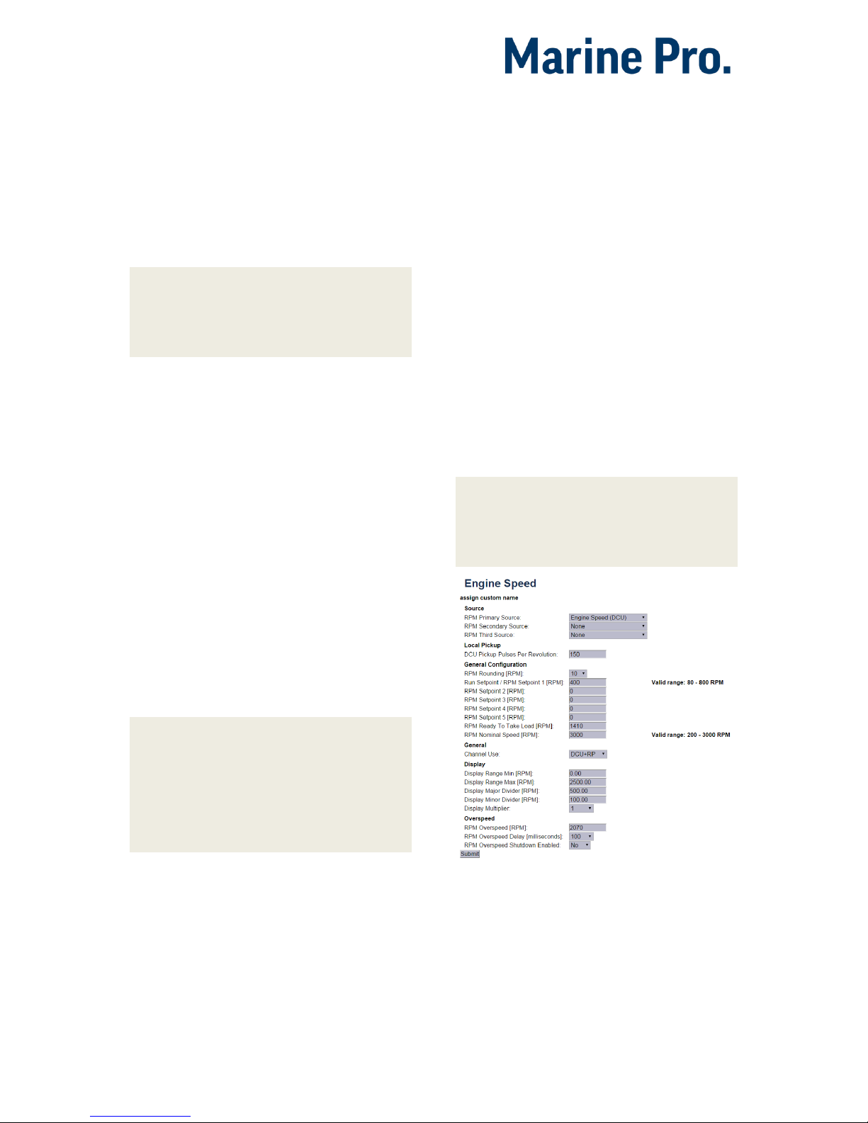
Engine Speed
This is where engine speed sensors
are configured, and the overspeed
setpoint is set. The majority of the
configuration is synchronized with
SDU.
Note! This section is central to any
installation. It provides the DCU with
data required to form an exact and
reliable reading of the engine speed.
HomeDCUI/O ConfigurationEngine Speed

Configuration Manual - 200E Series
Page 11
Source
The Engine Speed is constructed by
reading data from up to three sources
simultaneously. These three sources
are prioritized by the DCU. As long as
the RPM Primary Source is functional,
it is used to form the actual Engine
Speed. Should the RPM Primary Source
fail, the DCU uses the RPM Secondary
Source if available. Finally, the RPM
Third Source is used only when both
Primary and Secondary fails.
Each of the RPM Sources can be
configured to receive data from a
number of possible sensors.
Source
Comment
J1939
J1939 CANbus connected to
terminals C1P7-8.
J1939#2
J1939 CANbus #2 connected
to Flexible I/O #20-#21.
DCU
Magnetic pickup locally
connected to DCU,
terminals C4P1 and Flexible
I/O#18.
SDU
410
One of the two pickups
connected to the SDU safety
unit.
The SDU has a scheme for
selecting from its two
connected pickups.
SDU
404
Magnetic pickup locally
connected to SDU.
Local Pickup
If there is a pickup connected to the
DCU, or “DCU” is selected among the
sources above, then set the pulses per
revolution here.
General Configuration
RPM Rounding rounds off the
displayed value to nearest 1, 5 or 10
RPM.
RPM Setpoint is the RPM at which the
DCU indicates the engine is running,
and disconnects the cranker.
RPM Setpoint 2-5 are optional
setpoints that can be used in
conjunction with other sensors.
RPM Ready to take Load is a signal
that can be configured to an output. It
activates when that RPM is reached. It
deactivates when a stop command is
given, OR the speed drops below the
threshold, minus 15%.
RPM Nominal Speed is the engines
nominal speed, and is used to lower
the RPM Overspeed on the Overspeed
test to 95 % of the nominal speed.
General
Channel Use is the selection for where
the signal shall be displayed.
Select DCU+RP to display the
instrument in the DCU and in the RP.
Select DCU to display in DCU only, and
not in any connected RP.
Select RP to display in any connected
RP only, and not in the DCU.
Display
These values define how the
instrument widget is presented.
Display Range Min is the minimum
value displayed, normally 0 (zero).

Configuration Manual - 200E Series
Page 12
Display Range Max is the maximum
value displayed. For an engine running
at 1500 rpm nominally, a typical
maximum setting would be 1800 RPM.
Display Major Divider is where the
instrument widget writes an RPM
value, normally every 500 RPM.
Display Minor Divider is the tickmarks
between the major divider marks,
normally every 100 RPM.
Display Multiplier is the multiplier
value. The value is printed in the RPM
meter.
Overspeed
RPM Overspeed is the setpoint where
the DCU indicates overspeed.
RPM Overspeed Delay is the delay –in
milliseconds –before alarm or
shutdown. Typical setpoint is 100ms.
RPM Overspeed Shutdown Enabled is
where the overspeed behavior is
selected. Select Yes for the DCU to
shut down the engine. Select No to
disable overspeed shutdown.
Individual Speed Sensors
Note that
any
speed signal can be
connected here, and that this is
treated separately from the Engine
Speed signal configured above.
By configuring these sensors it is
possible to view the current RPM from
a individual speed sensor as opposed
the standard Engine Speed sensor that
acts on many inputs at once.
All Individual Speed sensors are
configured the same way.
Channel Use
This selects the panel the instrument
widget is displayed on. It is possible to
display the instrument on
The DCU engine panel, and
The RP remote panel, or
A combination of the two.
Sensor Unit
There is no choice; select RPM.
Sensor Range Min/Max
These values are fixed
Display Unit
There is no choice; select RPM.
Display Range Min
Select the low end of the scale.
Display Range Max
Select the high end of the scale.
Display Major Divider
Select the major tickmarks. These are
labeled with RPM values.
Display Minor Divider
Select the number of minor tickmarks
between the major tickmarks.
Display Multiplier
Select a value multiplier of 1, 10, 100
or 1000.
Event
Select type of event for this channel.
Configuration Manual - 200E Series
Page 13
Engine Load
First, configure either a 4-20mA, 0-5V
input or the J1939 PGN 0Xf003, SPN
92. Select then the engine load source
from the dropdown menu. Engine load
can now be used as an additional
setting when configuring alarms.
Transmission
The transmission menu are used for
Gear control, to Indicate current Gear
or as start interlock.
Gear control is enabled under
Home DCU User Interface.
When enabled the “Backlight” button
will be replaced with “Gear” in
instrument view. Selecting “Gear” will
open a new page on the DCU with
functions for Gear control as described
below.
Gear
The gear source is used as start
interlock when a gear is engaged
and/or to display the current gear.
Select the gear feedback source used.
To display current gear go to:
Home DCU User Interface
and enable “Show Gear Indicator
Instead Of All Ok”. To get the Gear
indicator as an half height vertical bar
graph go to: HomeDCUInterface
designPages. Choose witch page and
slot the gear indicator shall be shown.
Shaft Lock
If the DCU gear control is used, the
shaft lock input will prevent gear
changes when active. Select a Shaft
Lock source from the pull down menu.
Note! The shaft lock source must be a
switch input.
RPM Interlock
If the DCU gear control is used, the
RPM Interlock input will prevent gear
changes when active. Select a RPM
Interlock source from the pull down
menu.
Note! The RPM Interlock source must
be a switch input.
Shaft Speed
If the DCU gear control is used, the
Shaft Speed can be displayed wherever
the user wants. To choose its
placement go to:
HomeDCUInterfacedesignPages
It is possible to enable “Mirrored view”
which will put the zero value on top of
the gauge.
Switch
There are 21 configurable channels
available as switch inputs. Each
channel can be configured as an
(ordinary) engine switch input channel,
or it can be configured to perform a
function, like Automatic Start.

Configuration Manual - 200E Series
Page 14
HomeDCUI/O ConfigurationSwitch
First, select any of the enabled switch
channels. Then, for each channel, set
the following parameters.
Available functions for Switch inputs
The following functions are available
for the switch inputs.
The highlighted functions are the most
typically being used.
Function Name
Description
None
The channel is being used as
an (ordinary) engine sensor
switch input
Local Mode
Sets the panel to local mode,
meaning all external
commands are blocked.
Remote Mode
Sets the panel to remote mode,
meaning all local commands
are blocked.
Backlight 100%
Force backlight to 100%
Prelube override
The configured prelube
sequence is aborted
Prelube
complete
Signal shall come from the
prelube system, notifying the
panel that the prelube
sequence is completed. The
panel will commence start.
Start disabled
Start is disabled
Function Name
Description
Automatic mode
The panel accepts automatic
start/stop signals
Automatic start
Panel will commence the start
sequence. Requires Automatic
mode.
Automatic stop
Panel will commence the stop
sequence. Requires Automatic
mode.
Remote start
Same as the local start button.
Disabled if panel in local mode.
Remote stop
Same as the local stop button.
Disabled if panel in local mode.
Local Start
Local Start button
Local Stop
Local Stop button
Local
Acknowledge
Used to acknowledge all events
in the alarm list
Local/Remote
Acknowledge
Used to acknowledge all events
in the alarm list
Remote
Acknowledge
Used to acknowledge all events
in the alarm list
Shutdown
override
Makes all the configured
shutdown channels into alarm
channels, so engine will not
shut down automatically.
Engine overspeed shutdown is
however always enabled.
In gear
From gearbox on prop.
Engines. Disables start
attempts.
In Gear (Ahead)
From gearbox on prop.
Engines to indicate Ahead
gear.
In Gear (Astern)
From gearbox on prop.
Engines to indicate Astern
gear.
Toggle Crank
mode
Toggle between crank modes.
Power On
Toggle Sleep mode.
Function Use as
Select None if the channel is to be
used as an ordinary engine switch
input.

Configuration Manual - 200E Series
Page 15
Select any of the other functions
described above to assign that
function to the input channel.
Channel Use
This describes how the channel is
used.
Select Not in use if the channel shall
be disabled.
Select Event if the channel shall make
any form of event. An event can be a
warning, an alarm or an engine
shutdown.
Select Silent
Event for an active
channel, but no panel alarms. The
event will be available on
communication only.
Event
If any type of event was selected under
Channel Use, then select the type of
event here. It can be a Warning, Load
Reduction, Alarm or a Shutdown.
If None is selected, then the channel is
active but no events are created.
Input State
Normally Open means the contact
must close to make the event, whereas
Normally Closed means the contact
must open to make the event.
Delay Before Event
Choose the desired persistence time
before the channel activates the event.
This field is only available if the Event
field is selected.
1An engine speed source can be either the magnetic
pickup or the SAE J1939 CANbus signal connected
to the DCU.
Requires Running Engine
Typically, this shall be set to Yes for
pressure sensors, and to No for all
other sensors.
Select any of the other setpoints to
activate the channel at other rpm
values.
Requires in gear
If gear is required to monitor event
Must be in gear (Switch)
Requires Engine Load
Initial Delay
If the requires above is set Yes, set the
persistence time after the engine is
running until the channel is enabled.
This field is only available if all
requires that is selected are fulfilled.
Use as Additional Run
If the DCU has one pickup source only,
we recommend adding an engine oil
pressure switch as an engine running
indication.
Note! Do not use any other pressure
sensors –or any other signals –as
engine running
indication!
If two engine speed (pickup)
sources1are in use, then we
recommend leaving this off for
all switches, i.e. set to No.
Configuration Manual - 200E Series
Page 16
If one engine speed source only
is in use, then locate the engine
low oil pressure switch and use
this as the Additional Run
signal. Set to Yes.
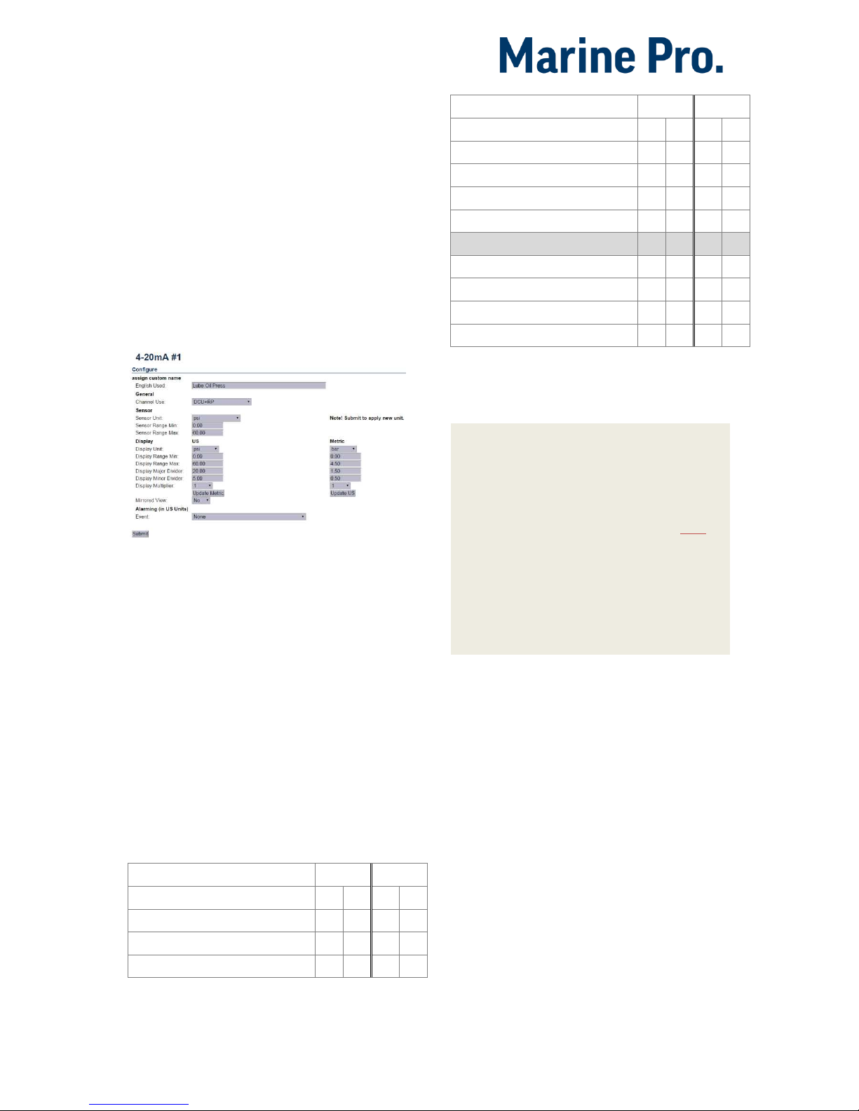
4-20mA
First, select one of the enabled 4-
20mA channels. Then, for each
selected channel, set the following.
HomeDCUI/O Configuration4-20mA
Channel Use
This selects the panel the instrument
widget is displayed on. It is possible to
display the instrument on
The DCU engine panel, and
The RP remote panel, or
A combination of the two.
It is also possible to suppress the
alarm events, as can be seen in the
following table overview.
Type of use
DCU
RP
D
E
D
E
Not in use
Event
x
x
DCU
x
Type of use
DCU
RP
D
E
D
E
DCU + Event
x
x
x
RP
x
RP + Event
x
x
DCU + RP
x
x
DCU + RP + Event
x
x
x
x
Silent Event
DCU + Silent Event
x
RP + Silent Event
x
DCU + RP + Silent Event
x
x
D = Displayed on panel
E = Event
Event = warning, alarm or shutdown
Silent Event = no local event; on communication only
Note! Normally - and in most cases -
the selection should be “DCU + RP +
Event”, as bolded and outlined in the
table above. This makes sure the
channel is displayed in the DCU and in
the RP, if and when an RP is installed.
If for example a signal is necessary in
the DCU engine panel only, and not in
the RP remote panel, then select DCU
+ Event from the selection.
Sensor
Sensor Unit
Select the unit, as printed on the
sensor. An oil pressure sensor might
for instance be in
Bar
or
psi
.
Sensor Range Min/Max
Select the sensor range values for min
and max, as printed on the sensor.
Other manuals for Marine Pro 200E Series
1
This manual suits for next models
4
Table of contents
Other auto maskin Control Panel manuals

Popular Control Panel manuals by other brands

Beckhoff
Beckhoff CP78 Series Installation and operating instructions

Truma
Truma CP plus VarioHeat operating instructions

Nordmann Engineering
Nordmann Engineering SPA Display Installation and operation manual

Firegear
Firegear PAVER CONTROL PANEL-TPSI Installation and operating instructions

Mitsubishi Electric
Mitsubishi Electric E1070 installation manual

U-Prox
U-Prox MP LTE quick start guide


