sageglass.com/resources
STEP 3:
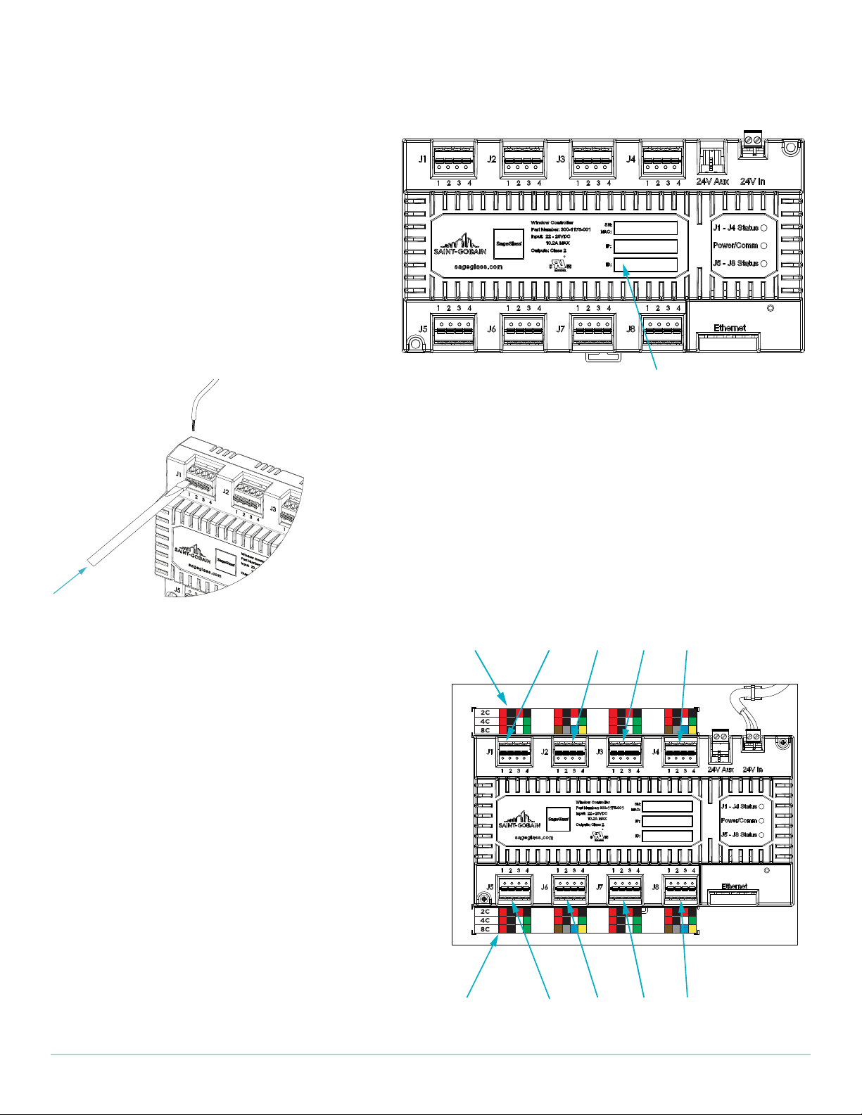
Populate wire terminals (1) with 2-Wire Frame Cables,
4-Wire Frame Cables, and/or 8-Conductor Cables
according to the project specific Wiring Diagram and
the wire color code guide that is on sticker (2) below
each terminal’s row. The wire color code guide
between the controllers shall be used for top and
bottom controllers.
Refer to appropriate row of the wire color code
guide depending on cables the system is equipped
with and follow the color code.
If it is a 2-Wire Frame Cable, 2C row of wiring guide is
used. One set will be black and red. Each terminal block
can hold two sets.
If it is 8-Conductor Cable, 8C row of wiring guide is
used. It will have two of each set and mount to the
adjacent terminal blocks (i.e. J1 and J2).
If it is 4-Wire Frame Cable, 4C row of wiring guide is
used. One set will be red, black, white and green. Each
terminal block will hold one set.
If system is equipped with mixed cable types,
8-Conductor Cables must go to adjacent terminal
blocks (i.e. J1 and J2), 4-Wire Frame Cables should be
connected to one terminal block and 2-Wire Frame
Cables should be connected to one terminal block
according to the color code.
2C
8C
2C
4C
8C
2C
4C
8C
FIGURE 11: CONTROLLER CONNECTION
1
1
2
2
1
1
1
1
1
1
2C
4C
8C
FIGURE 12: 2-WIRES
2C
4C
8C
FIGURE 13: 4-WIRES
2C
4C
8C
FIGURE 14: 8-CONDUCTOR CABLES
2C
4C
8C
FIGURE 15: MIXED WIRES