Junkers TR 100 User manual

6 720 604 574 (02.98)
OSW
TR 100
7 744 901 112
English
Correct function of this appliance can only be guaranteed if
these instructions are observed. Please hand this document
over to the customer.
Po polsku
W∆a∂ciwe funkcjonowanie zapewnione jest tylko pod
warunkiem przestrzegania niniejszej instrukcji. Prosimy o
zaƌczenie instrukcji Klientowi.
âesky
Bezvadné funkce je dosaÏeno pouze tehdy, budete-li dbát
tohoto návodu. Prosíme pfiedejte tento návod zákazníkovi.
Slovensky
Bezchybná funkcia je zaruãená len pri dodrÏaní tohto
návodu. Prosíme Vás, poskytnite zákazníkom túto
dokumentáciu.
Magyar
A készülék kifogástalan mæködését csak akkor tudjuk
szavatolni, ha a felhasználó az ebben a leírásban található
utasításokat betartja. Kérjük, adja át a Vevœnek ezt a
brosúrát.
Slovensko
Brezhibno delovanje bo zagotovljeno le ob upo‰tevanju teh
navodil. Prosimo, da kupec prejme ta navodila.
Hrvatski
Besprijekorno djelovanje jamãi se samo ako se strogo
po‰tuju ove opute. Mollmo da se ove upute uruãe kupcima.
Latviski
Nevainojama funkcionï‰ana ir garanteta tikai tad, ja ievero
‰o instrukciju. Ldzam to izsniegt pircïjam.
4476-00.1/O
JUNKERS
CERACONTROL
15
5
10
20°C
25
30

2
TR 100

3
TR 100
1
10 20
25
5
30
15°C
4476-01.1/O
2515
3010
5
20°C
eopfghi
lkmn
4476-02.1/O
i
JUNKERS
CERACONTROL
10
15
5
20°C 25
30
2
4476-03.1/O
JUNKERS
15
10
20°C
25
30
192
46
176
98
CERACONTROL
5
3
4192-03.1/G
0,3m
min.
0,3m
0,6m
1,2 - 1,5m
4
4476-05.1/O
JUNKERS
15
10
20°C
25
30
CERACONTROL
5
b1
b1
b1
b
a
b1
5

4
TR 100
English
1 Safety Instructions ........................................5
2 Application ....................................................5
3 Technical Data .............................................5
4 Mounting ......................................................6
5 Mains Connection ........................................6
6 Operation .....................................................7
7 Regulator Malfunction Message .................10
8 General Information ...................................11
9 Elimination of malfunctions ........................12
Po polsku
1 Wskazówki bezpieczeµstwa .......................13
2 Zastosowanie .............................................13
3 Dane technicznen ......................................13
4 Monta† regulatora ......................................13
5 Podƌczenie elektryczne ............................14
6 Obs∆uga ......................................................15
7 Komunikaty regulatora ...............................18
8 Wskazówki ogólne .....................................19
9 Zak∆ócenia i poszukiwanie przyczyn ..........20
âesky
1 Bezpeãnostní pfiedpisy .............................21
2 PouÏití .......................................................21
3 Technické údaje .......................................21
4 MontáÏ ......................................................21
5 Elektrické pfiipojení ...................................22
6 Obsluha ....................................................22
7 Hlá‰ení regulátoru ....................................25
8 V‰eobecné pokyny ...................................26
9 Hledání závad ...........................................27
Slovensky
1 Bezpeãnostné pokyny ..............................28
2 PouÏitie .....................................................28
3 Technické údaje .......................................28
4 MontáÏ ......................................................28
5 Elektrické zapojenie ..................................29
6 Obsluha ....................................................29
7 Hlásenia regulátora ..................................32
8 V‰eobecné pokyny ...................................33
9 Vyhºadávanie ch˘b ...................................34
Magyar
1 Biztonsági tájékoztató ................................ 35
2 A készülék alkalmazási területei ................ 35
3 Mæszaki adatok .......................................... 35
4 Felszerelés ................................................ 35
5 Elektromos csatlakozás ............................. 36
6 Kezelés ...................................................... 37
7 A szabályozó kijelzése ............................... 40
8 Általános tájékoztató .................................. 41
9 Hibakeresés ............................................... 42
Slovensko
1 Varnostni napotki .....................................43
2 Uporaba ...................................................43
3 Tehniãni podatki ....................................... 43
4 Namestitev ...............................................43
5 Elektriãni priklop ....................................... 44
6 Upravljanje ...............................................44
7 Regulator - poroãilo .................................. 47
8 Splo‰ni napotki .........................................48
9 Iskanje napak ........................................... 49
Hrvatski
1 Upute za siguran rad ................................ 50
2 Primjena ...................................................50
3 Tehniãki podaci ........................................50
4 MontaÏa ...................................................50
5 Elektriãni prikljuãak ................................... 51
6 PosluÏivanje .............................................51
7 Dojava regulatora .....................................54
8 Opçi napuci ..............................................55
9 TraÏenje neispravnosti ............................. 56
Latviski
1 Dro‰¥bas norÇd¥jumi ................................. 57
2 Lieto‰ana ..................................................57
3 Tehniskie dati ........................................... 57
4 MontÇÏa ...................................................57
5 Elektriskais pieslïgums ............................ 58
6 Apkalpo‰ana ............................................59
7 RegulÇtora zi¿ojums ................................62
8 VispÇr¥gi norÇd¥jumi ................................. 63
9 K∫mju meklï‰ana .................................... 64

English
TR 100
5
1 Safety Instructions
The regulator is to be used only in connec-
tion with the listed Junkers gas heating
units. The respective circuit diagram must
be observed.
The regulator must under no circum-
stances be connected to the 230 V
mains.
Before installing the regulator, the volt-
age supply (230 V, 50 Hz) to the heating
unit must be interrupted.
The regulator is not suited for installa-
tion in damp rooms.
2 Application
TR 100 is a room temperature regulator with a
digital time switch (daily programme for one
heating and one reduction starting time; equal
for all days of the week) for controlling the
Junkers gas heating units with continuous
control listed below.
TR 100 is in accordance with the regulations
and is recommended for floor-areas up to ap-
prox. 80 m
2
.
The room temperature regulator TR 100 is not
suited for buildings with underfloor heating
systems. In those buildings we recommend
the use of a regulator controlled by atmos-
pheric conditions.
2.1 Scope of delivery
TR 100 includes the room temperature regu-
lator with inserted brief operating instructions
(illustration ).
2.2 Accessory
An external room temperature sensor RF 1 in
addition to TR 100 is available as accessory.
For example, the use of this temperature sen-
sor is of advantage when the mounting loca-
tion of the regulator is not suited for measure-
ment of temperature (see chapter 4).
Furthermore, a remote control switch (e.g. a
telephone commander) can be connected
by
customers
(see chapter 6.7).
The remote control switch must be equipped
with a potential-free contact which is suited for
5 V DC.
3 Technical Data
Heating unit Mains
connection Malfunction
remote indi-
cator active
ZE/ZWE .. K... Illustr. no
ZE/ZWE .. - 1 K... Illustr. no
ZE/ZWE .. - 2 K... Illustr. no
ZE/ZWE .. - 1 A... Illustr. no
ZE/ZWE .. - 2 A... Illustr. no
ZR/ZWR/ZSR...-3 Illustr. no
ZR/ZWR/ZSR...-4 Illustr. no
Heating equipment
with
Bosch Heatronic Illustr. yes
9
9
9
10
10
10
10
11
Dimensions see illustration
Rated voltage 24 V DC
Rated current 0.02 A
Regulating range 5 to 30 °C
Regulator output constant,
2.5 to 21V DC
Permissible ambient
temperature 0 to +40 °C
Operating reserve approx. 2 hrs.
Protection class IP 20
2
3

English
6
TR 100
4 Mounting
Before mounting the regulator, the volt-
age supply (230 V, 50 Hz) to the heating
unit must be interrupted.
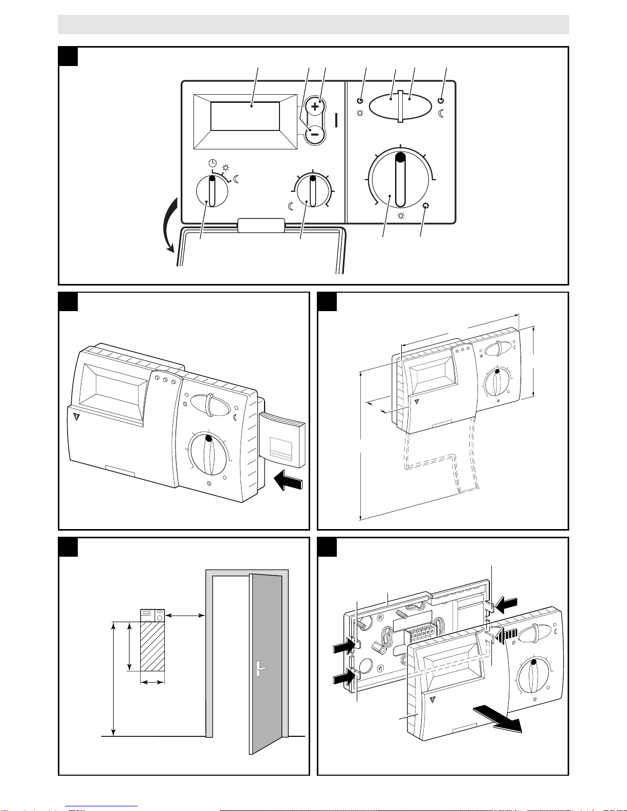
4.1 Selecting the mounting location
It is important for the regulation quality of
TR 100 to select a suitable mounting location.
The installation room must be suitable for the
temperature regulation of the complete heating
system. The radiators installed in those rooms
must not be equipped with thermostatic valves.
Instead, hand valves with pre-adjustment
should be installed so that the heating output of
the radiators in the installation room of TR 100
can be set to the lowest possible value.
For the mounting location, select an interior
wall if possible and take care that neither
draughts nor heat radiation (not from behind
the wall, either, e.g. through ducts or hollow
walls, etc.) can have effects on the regulator.
Adequate space must be provided above and
below the regulator so that the room air can
circulate unimpeded through the ventilation
openings (hatched area in illustration ).
If the above mentioned conditions cannot all
be met it is recommended to use the external
room temperature sensor RF 1 (accessory)
and to mount this on a more adequate loca-
tion.
When connecting the room temperature sen-
sor RF 1 the built-in sensor in the regulator is
automatically deactivated.
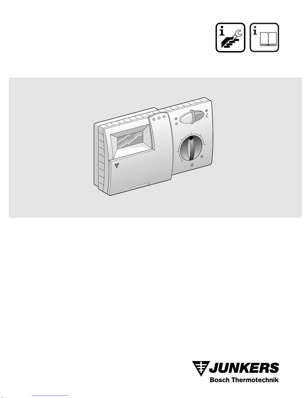
4.2 Mounting the regulator
• Loosen the top
(a)
from the base
(b)
de-
press the fasteners on the sides
(b1)
oft the
base and pull off the top
(a)
(illustration ).
• The base
(b)
can be mounted either
– with two screws
(c)
to a standard flush
connection box
(d)
dia. 55 mm
or
– with 4 dowels (6 mm) and tallow-drop
screws (dia. 3.5 mm) directly to the wall
(illustration );
Take care that the regulator is mounted in
the right position (the clip must be legible)!
• Connect with the mains accordingly (see
chapter 5).
• Fit the regulator top
(a)
.
4.3 Mounting the accessories
The accessories external room temperature
sensor RF 1 and remote control switch (if ex-
isting) must be mounted according to the reg-
ulations and the respective mounting instruc-
tions.
5 Mains Connection
The following conductor cross sections from
TR 100 to the heating unit must be used:
Considering the regulations, at least cables of
the construction type NYM must be used for
mains connection.
All 24 V cables (test current) must be laid sep-
arated from cables leading 230 V or 400 V so
that no inductive influencing can take place
(minimum distance100 mm).
In case that inductive external influences e.g.
from power current cables, contact wires,
transformer towers, radio and television sets,
amateur radio sets , microwave equipment, or
similar are to be expected the cables leading
test signals must be shielded.
The corresponding electrical connection plan
(illustration
to ) is to be followed :
5.1 Accessory mains connection
Connect the external room temperature sen-
sor RF 1 (if existing) as shown in
illustration .
If required, the cables of RF 1 can be extend-
ed with a cable with twisted twin conductors.
This will make sure that the measured values
of the sensor will not be influenced.
Connect the remote control switch (if existing)
as shown in illustration For minimum re-
quirements see chapter 2.2 accessories.
Whentheswitchingcontactof the remotecon-
trol switch is deactivated the heating system
will switch to economical operating mode, “F”
is displayed. When the switching contact is
activated the mode of operation set at the reg-
ulator is also activated (illustration ).
4
5
6
Length up to 20 m 0.75 mm
2
up to 1.5 mm
2
Length up to 30 m 1.0 mm
2
up to 1.5 mm
2
Length over 30 m 1.5 mm
2
9 11
7
8
8

English
TR 100
7
6 Operation
TR 100 has some operating elements which
are not needed often after installation and ini-
tial operation.
Therefore all operating elements which are
not needed often are covered with a lid.
The operating elements visible when the lid is
closed are part of the so-called “1
st
operating
level”. All other operating elements make up
the so-called “2
nd
operating level”.
All special operating conditions as well as
malfunctions are indicated with control lights
(only for heating equipment with Bosch
Heatronic).
When the lid is closed the time is shown.
6.1 The “1
st
operating level” (illustration
)
6.1.1 Control knob (k)
The room temperature to which the regulator
will keep in standard heating mode is set with
the control knob
(k)
.
The regulator will always regulate the temper-
ature to this value when the respective red
control light
(l)
is on.
If the control knob
(k)
is set to “5”, the re-
spective red control light
(l)
is off. The regula-
tor will then set the temperature to approx. 5°C
so that frost protection in this room is guaran-
teed. The heating system is switched off.
6.1.2 The operating conditions
Automatic operating mode
The basic setting of the regulator is automatic op-
erating mode.
Automatic operating mode means automatic
changeover between standard heating opera-
tion and economical operation at the times
pre-set with the time switch
(e)
.
During standard heating operation (=“day”),
the regulator regulates the room temperature
to the value set with the control knob
(k)
, the
respective red control light
(l)
is on.
During economical heating operation
(=“night”), the regulator regulates the room
temperature to the set economic temperature,
the respective red control light
(l)
is off. (Pre-
setting of economic temperature see
chapter 6.2.1)
Note:
Every time the automatic operating
mode is switched off a control light
comes on.
The operating mode can be
switched back to automatic opera-
tion at any time.
Button
“Continuous heating mode” (g)
When this button is depressed
(g)
continu-
ous heating operation is activated.
The regulator continuously regulates the room
temperature to the value set with the control
knob
(k)
.
The respective red control light
(f)
is on.
The respective red control light
(l)
is also on
(unless the control knob
(k)
is set to “5”).
The economical operating mode set at the
time switch is ignored.
The operating mode “continuous heating ” will
be activated until:
• the button
(g)
is depressed again; the
regulator will switch back to the automatic
operating mode
or
• the button
(h)
is depressed again; the reg-
ulator will switch back to economical operat-
ing mode.
In both cases the respective red control light
(f)
turns off and the regulator will regulate the room
temperature to the set value.
Depress this button if you exceptionally
go to bed late (e.g. because of a party). Switch
back to automatic operating mode later.
In case of an illness it might be more comfort-
able to have a higher room temperature (con-
tinuous heating operation). In this case, do not
forget to switch the regulator back to the auto-
matic operating mode.
During a winter holiday or during the summer,
a low room temperature for a longer period
can be selected by depressing the button
"continuous heating" and additionally reduc-
ing the temperature with the control knob
(k)
.
1
25
15
5
3010
20°C
☞
Tip

English
8
TR 100
Button
“Economical operating mode” (h)
When the button
(h)
is depressed the eco-
nomical operating mode is switched on.
The regulator continuously regulates the
room temperature to the value set with the
control knob "economic temperature" (set-
ting the economic temperature see
chapter 6.2.1).
The respective yellow control light
(i)
is on.
The respective red control light
(l)
is off.
The standard heating mode set at the time
switch is ignored.
The economical operating mode will be active
until
• midnight (00.00 hours)
or
• the button
(h)
is depressed again;
the regulator is set back to automatic oper-
ating mode
or
• the button
(g)
is depressed;
the regulator is set to continuous operating
mode.
In all cases the respective yellow control
light
(i)
will turn off and the regulator will regu-
late the temperature to the set values.
Use this mode if you
exceptionally
leave your house
(e.g. for shopping) and the
house should not be heated for this time. As
soon as you are back depress the button
(h)
again, the regulator is operating in automatic
mode again and will heat according to the set
temperature.
If you
leave the house in the evening
or if
you would like
to go to bed early
depress the
button
(h)
.The regulator terminates the eco-
nomical heating mode at midnight and will
switch back to the usual automatic operating
mode the next morning.
6.2 The “2
nd
operating range”
The “2
nd
operating range” is accessible after
opening the lid.
6.2.1Control knob
“economic temperature” (m)
With this control knob
(m)
the temperature
to which the regulator must regulate in the
automatic operating mode when set to
“economic”, as well as in "economical
operation mode"
(h)
.
6.2.2 General information on the timer
The time switch makes it possible to automat-
ically switch the heating system on once a day
at a pre-set time, and switch it off automatical-
ly once a day at a pre-set time. Those set
times are valid for all days.
Setting the time ( )
The display (e) shows the time (at initial oper-
ation or power failure over a longer period the
time pre-set by the factory):
The regulator is automatically set to the pro-
gramming mode when the lid is opened. Set
the control knob (n) to “ ” .
The time is set by depressing the buttons “-”
(o) or “+” (p) .
Brieflydepressing the buttonalters the timeby
1 minute, when the button is depressed for a
longer period the time runs faster forward or
backward.The seconds are setback to “0”. As
soon as the button is released the clock will
operate normally.
If no buttons are depressed the clock also op-
erates normally.
☞
Tip
10 20
25
30
15°C
5

English
TR 100
9
The time before 1200 hrs. (12 noon)can
be set faster with the “-” (o) button.
When no more alterations are necessary
close the lid.
Setting the starting time for heating
()
The regulator is automatically set to the pro-
gramming mode when the lid is opened. Set
the control knob (n) to the position (start
heating).
The display (e) shows the pre-set starting time
(at initial operation or power failure over a
longer period the starting time pre-set by the
factory):
The required starting time is set by depressing
the buttons
“-” (o) or “+” (p) .
Briefly depressing the button alters the start-
ing time by 10 minutes, when the button is de-
pressed for a longer period the time runs fast-
er forward or backward.
When no more alterations are necessary
close the lid.
Setting the starting time for the
economical operating mode ( )
The regulator is automatically set to the pro-
gramming mode when the lid is opened. Set
the control knob (n) to .
The display (e) shows the pre-set starting time
for economical operating mode (at initial oper-
ation or power failure over a longer period the
starting time pre-set by the factory):
The required starting time is set by depressing
the buttons
“-” (o) or “+” (p) .
Briefly depressing the button alters the start-
ing time for economical operation mode by 10
minutes, when the button is depressed for a
longer period the time runs faster forward or
backward.
When no more alterations are necessary
close the lid.
6.3 Operating reserve
The time switch has an operating reserve of
approx. 2 hours after having been in continu-
ous operation for at least one day. In case of
a power failure the display is no longer func-
tioning. If the power supply returns within the
operating reserve period the display of the
time and the starting times for standard heat-
ing mode and economical operating mode will
be re-activated.
Take care that the power supply is nev-
er interrupted for longer than 2 hours (do not
switch off the heating system in the summer
but select a low temperature at the regulator;
see chapter 6.1.2 tips for continuous heating).
6.4 Setting the summer and the standard
times
Proceed as described in the chapter “setting
the time”!
Do not alter the settings “start heating” and
“start economical operation”!
6.5 Brief operating instructions
The brief operating instructions are in the
compartment at the right side of the base
where all important functions are briefly de-
scribed (illustration ).
6.6 Regulator with connected room tem-
perature sensor RF 1 (accessory)
If a room temperature sensor RF 1 is connect-
ed the built-in sensor in the regulator is inef-
fective. Now the temperature conditions sur-
rounding the external room temperature sen-
sor are decisive.
Use the external room temperature sen-
sor when the mounting location of the regula-
tor has unfavourable measuring conditions
and which are not applicable for the entire
house e.g. insolation, a tiled stove nearby, etc.
6.7 Regulator with connected remote
control switch (by customers)
With this remote control switch (not included
in the Junkers delivery range) the heating sys-
tem can be activated from afar.
The most common application is probably the
use of a telephone commander. With this ap-
pliance the heating system can be switched
on via any telephone with aid of a personal
identification code.
☞
Tip
☞
Tip
2
☞
Tip

English
10
TR 100
Before leaving the house the regulator is set
to the mode required at return (automatic op-
eration mode or continuous heating opera-
tion).
Then the switching contact of the remote con-
trol switch is deactivated, the regulator is ope-
rating in the economical operating mode. The
respective red control light (l) is off.
Appears simultaneously in the display:
If the switching contact is activated (e.g. by a
coded telephone signal) the regulator oper-
ates in the pre-set operating mode.
It will be warm in the house late at night/
early in the morning if the regulator is set to
the position (continuous heating)(g) before
leaving the house, and the switch is deactivat-
ed afterwards. Do not forget to set the regula-
tor back to ”automatic operating mode“ after
returning to the house.
If the house is left for a longer period you
should consider that it could become a lot
cooler (walls could cool down etc.) and there-
fore it will take a longer time to heat up. Switch
the heating system on in time.
7 Regulator Malfunction Message
Malfunction remote indicator
(not available with all heating systems)
For heating equipment with Bosch Heatronic,
a malfunction in the heating eequipment is
routed to the regulator.
If the heating system has a malfunction mes-
sage the control light will indicate (l).
Note: In this case please proceed as stat-
ed in the operating instructions of
the heating unit or contact your lo-
cal expert for heating systems.
☞
Tip

English
TR 100
11
8 General Information
... and hints on saving energy:
When the regulator settings are altered the
regulator reacts with a time lag. Every 20 sec-
onds the processor compares all desired and
actual values and carries out all necessary
corrections with the necessary speed.
The room in which the room temperature reg-
ulator is mounted (control room) determines
the temperature for all other rooms.
I.e. the room temperature in the control room
acts as a control input for the entire heating
network.
For this reason all thermostat regulated radia-
tors located in the control room must be
opened completely at all times. Otherwise the
thermostat valves would reduce the heat sup-
ply although the regulator constantly requires
more heat (see also chapter 4.1).
If in the adjoining rooms a lower temperature
is wanted or if the radiator should be turned off
completely, the (thermostatic) radiator valves
must be set accordingly.
Since the room where the room temperature
regulator is mounted acts as a control room,
any external heating sources (e.g. insolation,
tiled stove, etc.) can result in insufficient
heating of the remaining rooms (the radiators
stay cold). In order to avoid this the room
temperature sensor RF 1 can be used
according to the notes in chapter 2.2,
chapter 5.1 and chapter 6.6.
When the room temperature is reduced dur-
ing the day or during the night a lot of energy
can be saved.
If the room temperature is reduced by 1 K
(°C) this can save up to 5% of energy.
It is not recommended to let the temperature
of daily heated rooms drop below +15°C.
When the room is heated up again the com-
fortableness is diminished by the walls which
are cooled down. So if one wants a real com-
fortable room temperature the regulator must
be turned up and so a lot more energy is used
up than is in case of an even heat supply.
If the building has good thermal insulation it is
possible that the set economic temperature is
not reached. But even in this case energy is
saved since the heating system is not activat-
ed.
In this case the starting time for economical
operating mode can be set earlier.
Do not let windows stand ajar for airing the
rooms since this would constantly withdraw
heatfrom the room withoutimproving the air in
the room considerably. Do avoid continuous
airing!
It is better to air the room briefly but properly
(open the windows completely).
Set the temperature regulator to a lower value
during airing.

English
12
TR 100
9 Elimination of malfunctions
Malfunction Cause Elimination
the set room temperature
is not reached thermostat valve(s) are
installed in the room where
the regulator is mounted
have the thermostat valve
replaced by a hand valve or
completely open the thermo-
stat valve(s)
the flow temperature of the
heating unit is set too low set the flow temperature to a
higher value
the pre-set room tempera-
ture is exceeded the mounting location of the
regulator is inappropriate,
e.g.outside wall, close to a
window, draught,...
select a more appropriate
mounting location (see chap-
ter mounting) or use an exter-
nal temperature sensor
(accessory)
too high variation in room
temperature temporary influence of
external heating sources on
the regulator e.g.by insola-
tion, room lighting, TV, fire-
place, etc.
select a more appropriate
mounting location (see chap-
ter mounting) or use an exter-
nal temperature sensor
(accessory)
rise in temperature
instead of reduction the time of day is set incor-
rectly at the time switch check the setting
too high room tempera-
ture in economic operat-
ing mode
high regenerative capacity
of the building select an earlier starting time
for economic operating mode
wrong or no regulation wrong wiring of the regulator check the wiring according to
the circuit diagram and correct
if necessary
no display or the colon is
not indicating very short power failure switch off and on the heating
unit main switch

Po polsku
TR 100
13
1 Wskazówki bezpieczeµstwa
Regulator mo†e byç wy∆åcznie stosowany
z wymienionymi ogrzewaczami gazowymi
firmy Junkers. Nale†y przy tym
przestrzegaç odpowiedni plan przy∆åczeµ.
Nie wolno pod∆åczaç regulatora
bezpo∂rednio do sieci 230 V.
Przed monta†em regulatora nale†y
przerwaç zasilanie (230 V, 50 Hz) do
ogrzewacza.
Regulator nie nadaje si™ do monta†u w
pomieszczeniach wilgotnych.
2 Zastosowanie
Regulator TR 100 jest pokojowym
regulatorem temperatury wyposa†onym w
cyfrowy zegar sterujåcy ((program dzienny,
punkt ogrzewania i wyƌczania; takie same dla
wszystkich dni tygodnia) przeznaczonym do
regulacji ogrzewaczy gazowych firmy
Junkers.
Model TR 100 zalecany jest do ogrzewania
pomieszczeµ o powierzchniach do 80 m2i
odpowiada odpowiednim przepisom.
TR 100 nie poleca si™ jako pokojowego
regulatora temperatury do systemów z
ogrzewaniem pod∆ogowym i klimatyzacjå. W
takich pomieszczeniach zaleca si™
stosowanie regulacji pogodowej.
2.1 Wyposa†enie
Do wyposa†enia modelu TR 100 nale†y
pokojowy regulator temperatury z wsuni™tå
skróconå wersjå instrukcji obs∆ugi (szkic ).
2.2 Osprz™t dodatkowy
Do modelu TR 100 dostarczany jest
zewn™trzny pokojowy czujnik temperatury
RF 1. Jego zainstalowanie wydaje si™
sensowny w takich okoliczno∂ciach, kiedy
miejsce monta†u regulatora nie nadaje si™ do
pomiarów temperatury (patrz rozdzia∆ 4).
W dalszej kolejno∂ci mo†e byç pod∆åczony
zdalny wƌcznik (np. w formie komandera
telefonicznego (patrz rozdzia∆ 6.7).
Zdalny w∆åcznik musi posiadaç potencjalnie
wolny kontakt, który nadaje si™ do napi™cia
5 V DC.
3 Dane technicznen
4 Monta† regulatora
Przed monta†em regulatora nale†y
przerwaç zasilanie (230 V, 50 Hz) do
ogrzewacza.
4.1 Wybór miejsca monta†u
Bardzo wa†nym czynnikiem wp∆ywajåcym na
jako∂ç regulacji TR 100 jest optymalny wybór
miejsca monta†u. Pomieszczenie, w którym
zamontowany b™dzie regulator, powinno byç
reprezentatywne (pod wzgl™dem
temperatury) dla ca∆ego systemu centralnego
ogrzewania. Zainstalowane w tym
pomieszczeniu grzejniki nie powinny byç
wyposa†one w zawory z g∆owicami
termostatycznymi. Zaleca si™ stosowanie w
tym miejscu zaworów sterowanych r™cznie z
wst™pnå regulacjå, tak aby wydajno∂ç
TYP Przyƌczenie
elektryczne Aktywny
wskaçnik
zak∆óceµ
ZE/ZWE .. K... Szkic nie
ZE/ZWE .. - 1 K... Szkic nie
ZE/ZWE .. - 2 K... Szkic nie
ZE/ZWE .. - 1 A... Szkic nie
ZE/ZWE .. - 2 A... Szkic nie
ZR/ZWR/ZSR...-3 Szkic nie
ZR/ZWR/ZSR...-4 Szkic nie
Ogrzewacze z
systemem
Bosch-Heatronic Szkic tak
9
9
9
10
10
10
10
11
2
Wymiary urzådzenia patrz szkic
Napi™cie znamionowe 24 V DC
Pråd znamionowy 0,02 A
Zakres regulacji
temperatury 5…30 °C
Sygna∆ na wyj∂ciu
regulatora regulacja ciåg∆a,
2,5…21 V DC
Dopuszczalna
temperatura otoczenia 0…+40 °C
Rezerwa pracy ok. 2 godzin
Klasa ochrony IP 20
3

Po polsku
14
TR 100
grzejników w pomieszczeniu monta†owym
TR 100 mog∆a byç regulowany tylko w bardzo
wåskim zakresie.
Jako miejsce monta†u najlepiej wybraç ∂cian™
wewn™trznå i uwa†aç, aby pozbawiona ona
by∆a dodatkowych czynników fa∆szujåcych
odczyt temperatury przez regulator
(nagrzewanie przez promienie s∆oneczne,
kumulacja ciep∆a pochodzåcego z grzejników,
wych∆odzenie ∂ciany przez przeciågi itp.)
Poni†ej i powy†ej regulatora nale†y
pozostawiç wystarczajåco du†o miejsca, tak
aby cyrkulacja powietrza nie by∆a
ograniczona, a samo powietrze mog∆o
swobodnie przedostaç si™ przez otwory
znajdujåce si™ w obudowie urzådzenia
(zakreskowana powierzchnia na rysunku ).
Je∂li wszystkie wy†ej wymienione warunki nie
mogå byç spe∆nione, zaleca si™
zainstalowanie i monta† w odpowiednim
miejscu zewn™trznego czujnika temperatury
RF 1 (osprz™t dodatkowy).
W momencie pod∆åczenia zewn™trznego
czujnika temperatury RF 1 zamontowany w
regulatorze czujnik zostaje automatycznie
odƌczony.
4.2 Monta† regulatora
• Zdjåç górnå cz™∂ç (a) od podstawki (b),
wcisnåç boczne haczyki (b1) znajdujåce si™
w podstawie i ∂ciågnåç górnå cz™∂ç (a)
regulatora (szkic ).
• Podstaw™ (b) mo†na zamontowaç w
nast™pujåcy sposób:
– za pomocå dwóch wkr™tów (c) do
typowej puszki podtynkowej (d) o
∂rednicy 55 mm,
lub
– bezpo∂rednio na ∂cianie, wiercåc cztery
otwory i zamocowaç 4 ko∆kami
rozporowymi (6 mm) oraz wkr™tami
(3,5 mm) z p∆askå g∆ówkå (szkic );
zwróciç przy tym uwag™ na prawid∆owy
kierunek monta†u (czytelne oznaczenie
zacisków)!
• dokonaç odpowiedniego pod∆åczenia
elektrycznego (patrz rozdzia∆ 5).
• nasadziç górnå cz™∂ç regulatora (a).
4.3 Monta† osprz™tu dodatkowego
Osprz™t dodatkowy tj. zewn™trzny czujnik
temperatury RF 1 i zdalny w∆åcznik (je∂li
przewidziane do monta†u) nale†y zabudowaç
wzgl. pod∆åczyç zgodnie z odpowiednimi
przepisami i wskazówkami.
5 Podƌczenie elektryczne
Stosowaç nast™pujåce przekroje przewodu
∆åczåcego regulator TR 100 z kot∆em:
Przy uwzgl™dnieniu obowiåzujåcych
przepisów nale†y stosowaç do pod∆åczenia co
najmniej kable elektryczne typu NYM.
W celu wyeliminowania niekorzystnych
oddzia∆ywaµ indukcyjnych, wszystkie
przewody regulatora 24 V (pråd pomiarowy)
nale†y prowadziç w oddaleniu (co najmniej
100 mm) od kabli zasilajåcych (230 V lub
400 V).
W przypadku, gdy mo†na spodziewaç si™
dodatkowych zewn™trznych zak∆óceµ
indukcyjnych spowodowanych np. przez
kable zasilajåcymi o du†ym napi™ciu,
przewody jezdne, trafostacje, sygna∆y
radiowe lub telewizyjne, amatorskie
radiostacje, kuchenki mikrofalowe itp.,
przewody nale†y zaekranowaç.
Nale†y przestrzegaç odpowiedni plan
po∆åczeµ elektrycznych (szkic do ):
5.1 Pod∆åczenie elektryczne osprz™tu
dodatkowego
Zewn™trzny czujnik temperatury RF 1 (je∂li
ma byç zamontowany) powinien byç
podƌczony zgodnie ze szkicem .
W razie konieczno∂ci przewody czujnika RF 1
mogå byç przed∆u†one skr™conym kablem
dwu†y∆owym. W ten sposób mo†na zapewniç,
†e warto∂ci pomiarowe czujnika nie b™då
przek∆amywane.
4
5
6
D∆ugo∂ç przewodu
do 20 m 0,75 mm2 do 1,5 mm2
D∆ugo∂ç przewodu
do 30 m 1,0 mm2 do 1,5 mm2
Wi™cej ni† 30 m 1,5 mm2
9 11
7

Po polsku
TR 100
15
W∆åcznik zdalnie sterowany (je∂li fabrycznie
zabudowany) pod∆åczyç zgodnie ze
schematem na szkicu . Odpowiednie
wymagane warunki podane så w rozdziale
patrz rozdzia∆ 2.2 osprz™t dodatkowy.
Przy zamkni™tym kontakcie w∆åcznika
zdalnego sterowania ogrzewanie przestawia
si™ na tryb "nocny" (oszcz™dny), a na
wskaçniku pojawia si™ "F". Przy otwartym
kontakcie przej™ty zostaje ustawiony
pierwotnie na regulatorze tryb pracy
(szkic ).
6 Obs∆uga
Model TR 100 posiada kilka elementów
obs∆ugowych, które po instalacji i uruchomieniu
b™då u†ywane bardzo rzadko.
Z tego powodu wszystkie elementy obs∆ugowe, z
których korzystamy bardzo rzadko, zamkni™te så
specjalnå klapkå przesuwnå.
Wszuystkie widoczne elementy obs∆ugowe
widoczne po zamkni™ciu klapki nale†å do tzw.
"pierwszego poziomu obs∆ugi". Wszystkie inne
tworzå tzw. "drugi poziom obs∆ugi".
Wszystkie stany specjalne regulatora
pokazywane så przez odpowiednie lampki
kontrolne jak równie† wskazania zak∆óceµ lub
awarii (tylko przy ogrzewaczach z systemem
Bosch Heatronic).
Przy zamkni™tej klapie wskazywany jest aktualny
czas.
6.1 "Pierwszy poziom obs∆ugi" (szkic )
6.1.1 Pokr™t∆o (k)
Za pomocå pokr™t∆a (k) ustawiana jest
temperatura pomieszczenia, na którå
regulator w normalnym trybie ogrzewania
powinien regulowaç.
Regulator reguluje wtedy zawsze do takiej
temperatury, kiedy pali si™ czerwona lampka
kontrolna (l).
Je∂li pokr™t∆o (k) znajduje si™ na "5", nie
za∂wici si™ lampka kontrolna (l). Regulator
reguluje wtedy do temperatury ok. 5 °C i
zapewnia tym samym ochron™ przed mrozem
w pomieszczeniu. Oznacza to, †e ogrzewanie
jest wyƌczone.
6.1.2 Przeƌczniki trybu pracy
Tryb automatyczny
Podstawowym ustawieniem regulatora jest
automatyczny tryb pracy.
Tryb automatyczny oznacza automatyczne
prze∆åczanie pomi™dzy okresami temperatury
"dziennej" (normalnej), a okresami
temperatury "nocnej" (obni†onej) wg.
programu nastawionego na zegarze
cyfrowym (e).
Regulator obs∆uguje ogrzewanie w trybie
normalnym (dziennym) do ustawionej na
pokr™tle (k) temperatury, czerwona lampka
kontrolna (l) ∂wieci si™ ca∆y czas.
Regulator obs∆uguje ogrzewanie w trybie
oszcz™dnym (nocnym) do ustawionej
temperatury "nocnej", czerwona lampka
kontrolna (l) nie ∂wieci si™. (Ustawianie
temperatury "nocnej" patrz rozdzia∆ 6.2.1)
Wskazówka: Ka†de opuszczenie trybu
automatycznego pokazywane
jest przez lampk™ kontrolnå
Ka†dorazowo mo†na
ponownie przywróciç tryb
automatyczny.
Tryb pracy ciåg∆ej (g)
Naci∂ni™cie przycisku (g) w∆åcza tryb pracy
ciåg∆ej.
Regulator obs∆uguje pomieszczenie na
podstawie nastawy na pokr™tle (k)
temperatury "dziennej" (normalnej).
Czerwona lampka kontrolna (f) ∂wieci si™.
Równie† czerwona lampka kontrolna (l)
∂wieci si™ (z wyjåtkiem ustawienia pokr™t∆a (k)
w pozycji "5").
Ustawiony na zegarze tryb "nocny"
(oszcz™dny) jest ignorowany.
Tryb pracy "ogrzewanie ciåg∆e" pozostaje
utrzymany tak d∆ugo a†:
• ponownie naci∂ni™ty zostanie przycisk
(g);ponownie zostanie wtedy w∆aczony
tryb automatyczny
lub
• wci∂ni™ty zostanie przycisk (h); ustawiony
zostanie wtedy tryb oszcz™dny
8
8
1
25
15
5
3010
20°C

Po polsku
16
TR 100
W obu przypadkach ga∂nie czerwona lampka
kontrolna (f) a regulator ogrzewa do
odpowiednio w∆a∂ciwej temperatury.
Wcisnåç ten przycisk, je∂li wyjåtkowo
idziecie póçniej spaç do ∆ó†ka (np. party).
Potem ponownie prze∆åczyç na tryb
automatyczny.
Równie† w czasie choroby tryb ogrzewania
ciåg∆ego mo†e byç przyjemny. Nie nale†y
jednak równie† wtedy zapomnieç o
ponownym przeƌczeniu na tryb
automatyczny.
Podczas urlopu zimowego lub w lecie mo†na
wybraç na d∆u†szy czas ni†szå temperatur™.
W tym celu nale†y nacisnåç przycisk
ogrzewania ciåg∆ego i dodatkowo obni†yç
temperatur™ na pokr™tle (k).
Przycisk "trybu oszcz™dnego"
(nocnego) (h)
Wci∂ni™cie przycisku (h) uruchamia tryb
oszcz™dny.
Regulator obs∆uguje do ustawionej na
pokr™tle "temperatury nocnej" (regulacja
temperatury nocnej patrz rozdzia∆ 6.2.1).
˝ó∆ta lampka kontrolna (i) ∂wieci si™.
Czerwona lampka kontrolna (l) nie ∂wieci si™.
Ustawiony na zegarze tryb "normalny" jest
ignorowany.
Tryb pracy "ogrzewanie oszcz™dne"
pozostaje utrzymany tak d∆ugo a†:
• osiågni™ta zostanie pó∆noc (godzina 00.00)
lub
• ponownie naci∂ni™ty zostanie przycisk
(h); ponownie zostanie wtedy wƌczony
tryb automatyczny
lub
• wci∂ni™ty zostanie przycisk (g);
ustawiony zostanie wtedy tryb ogrzewania
ciåg∆ego.
In ka†dym z przedstawionych przypadków
ga∂nie †ó∆ta lampka kontrolna (i) a regulator
ogrzewa do odpowiednio w∆a∂ciwej
temperatury.
Nale†y stosowaç t™ funkcj™, je∂li
czasami opuszczacie Paµstwo mieszkanie
(np. na czas zakupów) i mieszkanie nie musi
byç ogrzewane. Zaraz po powrocie nale†y
ponownie wcisnåç przycisk (h), regulator
zaczyna ponownie pracowaç w trybie
automatycznym i ogrzewa do odpowiedniej
w∆a∂ciwej temperatury.
Je∂li opuszczacie Paµstwo mieszkanie
wieczorem lub k∆adziecie si™ wcze∂niej spaç,
nale†y wcisnåç przycisk (h). Regulator o
pó∆nocy koµczy ogrzewanie w trybie
oszcz™dnym (nocnym) i grzeje rano jak
zwykle w trybie automatycznym.
6.2 "Drugi" poziom obs∆ugi
"Drugi" poziom obs∆ugowy dost™pny jest po
otwarcie klapki.
6.2.1 Pokr™t∆o "temperatura
oszcz™dna" (m)
Na pokr™tle (m) ustawiana jest temperatura
w pomieszczeniu, do której regulator
obs∆uguje w trybie automatycznym przy
"oszcz™dzaniu" i trybie "nocnym" (h).
6.2.2 Informacje ogólne o zegarze
Zegar umo†liwia jeden raz dziennie
automatycznie w∆åczyç i wy∆åczyç ogrzewanie
w wybranym czasie. Oba punkty czasowe så
takie same dla wszystkich dni.
Nastawianie zegara ( )
Na wskaçniku (e) pojawia si™ aktualny czas (w
czasie uruchomienia lub po d∆u†szym
przerwaniu dop∆ywu prådu pojawia si™
ustawienie fabryczne):
Po otwarciu klapki ustawiany jest
automatycznie tryb programowania. Obróciç
pokr™t∆o (n) na symbol " ".
Ustawienie czasu nast™puje poprzez
naci∂ni™cie przycisków "-" (o) lub "+" (p).
Krótkie naci∂ni™cie przestawia zegar o 1
minut™, przy d∆u†szym naciskaniu nast™puje
szybkie przeskakiwanie czasu do przodu lub
ty∆u. Sekundy ustawiane så przy tym na "0".
☞
Tip
☞
Tip
10 20
25
30
15°C
5

Po polsku
TR 100
17
Po zwolnieniu nacisku na przycisk zegar
biegnie dalej. Je∂li przycisk nie jest wciskany,
zegar równie† biegnie dalej.
Czasy przed godzinå 12.00 (po∆udnie)
pozwalajå si™ przy u†yciu przycisku "-" (o)
szybciej ustawiç.
Zamknåç klapk™ po dokonaniu wszystkich
niezb™dnych zmian.
Ustawienie poczåtku
ogrzewania ( )
Po otwarciu klapki ustawiany jest
automatycznie tryb programowania. Obróciç
pokr™t∆o (n) na symbol " " (poczåtek
ogrzewania).
Na wskaçniku (e) pojawia si™ ostatnio
ustawiony poczåtek ogrzewania ((w czasie
uruchomienia lub po d∆u†szym przerwaniu
dop∆ywu prådu pojawia si™ ustawienie
fabryczne):
W∆a∂ciwy poczåtek ogrzewania ustawiany jest
za pomocå przycisków "-" (o) lub "+" (p).
Krótkie naci∂ni™cie przestawia punkt
rozpocz™cia ogrzewania o 10 minut™, przy
d∆u†szym naciskaniu nast™puje szybkie
przeskakiwanie punktu czasowego do przodu
lub ty∆u.
Zamknåç klapk™ po dokonaniu wszystkich
niezb™dnych zmian.
Ustawienie poczåtku
oszcz™dzania ( )
Po otwarciu klapki ustawiany jest
automatycznie tryb programowania. Obróciç
pokr™t∆o (n) na symbol " ".
Na wskaçniku (e) pojawia si™ ostatnio
ustawiony poczåtek oszcz™dzania ((w czasie
uruchomienia lub po d∆u†szym przerwaniu
dop∆ywu prådu pojawia si™ ustawienie
fabryczne):
W∆a∂ciwy poczåtek oszcz™dzania ustawiany
jest za pomocå przycisków "-" (o) lub "+" (p).
Krótkie naci∂ni™cie przestawia punkt
rozpocz™cia oszcz™dzania o 10 minut™, przy
d∆u†szym naciskaniu nast™puje szybkie
przeskakiwanie punktu czasowego do przodu
lub ty∆u.
Zamknåç klapk™ po dokonaniu wszystkich
niezb™dnych zmian.
6.3 Rezerwa pracy
Zegar po jednodniowym trybie pracy
dysponuje rezerwå energii podtrzymujåcej
prac™ na ok. 2 godziny. Po wy∆åczeniu
dop∆ywu prådu ga∂nie wskaçnik. Je∂li
zasilanie zostanie w∆åczone w ciågu okresu
rezerwy pracy, zachowane zostajå ustawienia
czasu, poczåtku ogrzewania i oszcz™dzania.
Uwa†aç, aby zanik dop∆ywu energii
elektrycznej nie trwa∆ d∆u†ej ni† 2 godziny (nie
wy∆åczaç ogrzewania w lecie, ale wybraç
ni†szå temperatur™; patrz rozdzia∆ 6.1.2
Wskazówka do ogrzewania ciåg∆ego).
6.4 Ustawianie czasu letniego/zimowego
Wykonaç procedury jak w rozdziale
"Ustawianie zegara"!
Nie zmieniaç punktów czasowych
"rozpocz™cie ogrzewania" i rozpocz™cie trybu
oszcz™dzania".
6.5 Skrócona instrukcja obs∆ugi
W skrytce po prawej stronie znajduje si™
skrócona instrukcja obs∆ugi, w której opisane
så wszystkie wa†ne informacje (szkic ).
6.6 Regulator z podƌczonym czujnikiem
temperatury pomieszczenia RF 1
(osprz™t dodatkowy)
Przy podƌczonym czujniku temperatury
pomieszczenia RF 1 nie dzia∆a zainstalony
czujnik w regulatorze. Dlatego miarodajnymi
wynikami så pomiary w obszarze dzia∆ania
zewn™trznego czujnika temperatury.
Zastosowaç czujnik temperatury, je∂li w
miejscu monta†u regulatora panujå
niekorzystne warunki pomiarowe, które nie så
reprezentatywne (miarodajne) dla ca∆ego
mieszkania np. nagrzewanie przez promienie
s∆oneczne, kumulacja ciep∆a z pieca
kaflowego, wych∆odzenie ∂ciany przez
przeciågi itp.
☞
Tip
☞
Tip
2
☞
Tip

Po polsku
18
TR 100
6.7 Regulator z podƌczonym zdalnym
wƌcznikiem (fabrycznie)
Poprzez ten dodatkowy wƌcznik (nie ma go w
programie dostaw Junkersa) ogrzewanie
mo†e byç w∆åczane na odleg∆o∂ç.
Najcz™stszym zastosowaniem jest pos∆u†enie
si™ komanderem telefonicznym. Dzi™ki temu
mo†liwe jest w∆åczenie ogrzewania poprzez
ka†dy telefon po podaniu osobistego kodu
sterujåcego.
Przed opuszczeniem domu nale†y ustawiç na
regulatorze tryb pracy, w jakim mieszkanie
ma byç ogrzewane po powrocie (tryb
automatyczny lub ogrzewanie ciåg∆e).
Po tym zamkni™ty zostaje w∆åcznik zdalnie
sterowanego wƌcznika, regulator pracuje w
trybie "oszcz™dzania", czerwona lampka
kontrolna (l) nie pali si™. Jednocze∂nie na
wskaçniku pojawia si™ symbol:
Je∂li w∆åcznik zostanie otwarty (np. poprzez
zakodowany sygna∆ telefoniczny), regulator
pracuje wg. wcze∂niej nastawionego
programu.
Mieszkanie jest równie† póçnym
wieczorem/wczesnym rankiem przyjemnie
ciep∆e, je∂li ustawicie Paµstwo regulator przed
opuszczeniem domu w pozycj™
(ogrzewanie ciåg∆e) (g) i dopiero wtedy
zakmniecie w∆åcznik. Nie nale†y jednak
zapomnieç ustawiç regulator po powrocie na
tryb automatyczny.
W czasie d∆u†szej nieobecno∂ci nie nale†y
zapominaç, †e mieszkanie (∂ciany itd.) så
silnie wych∆odzone i potrzebujå d∆u†szego
nagrzewania. Odpowiednio wcze∂nie nale†y
dlatego w∆åczyç ogrzewanie.
7 Komunikaty regulatora
Wskaçnik uszkodzenia/b∆™du
(nie we wszystkich urzådzeniach
grzewczych)
W modelach ogrzewaczy wyposa†onych w
system Bosch Heatronic uszkodzenie/bƌd
przekazywany jest z ogrzewacza do
regulatora.
Przy uszkodzeniu ogrzewacza miga lampka
kontrolna (l).
Wskazówka: w takim przypadku nale†y
post™powaç zgodnie ze
wskazówkami zawartymi w
instrukcji obs∆ugi ogrzewacza
lub nale†y poinformowaç
odpowiedzialnego fachowca z
autoryzowanego serwisu.
☞
Tip

Po polsku
TR 100
19
8 Wskazówki ogólne
... i porady oszcz™dnego gospodarowania
energiå:
Podczas zmiany nastawieµ regulatora
regulator reaguje z odpowiednim
opóçnieniem czasowym. Procesor co 20
sekund porównuje wszystkie warto∂ci
rzeczywiste i nastawione i dokonuje po tym
odpowiednie korekty.
Pomieszczenie (pomieszczenie
reprezentatywne), w którym zainstalowany
jest regulator, ustala temperatur™ dla innych
pomieszczeµ w mieszkaniu.
Oznacza to, †e temperatura w pomieszczeniu
reprezentatywnym jest traktowana jako
warto∂ç odniesienia dla ca∆ej sieci grzewczej.
Z tego te† powodu je∂li w pomieszczeniu
reprezentatywnym zainstalowane så grzejniki
wyposa†one w g∆owice z zaworami
termostatycznymi muszå byç one zawsze
ca∆kowicie otwarte. W przeciwnym wypadku
g∆owice z zaworami termostatycznymi d∆awiå
dop∆yw ciep∆a, mimo †e regulator ca∆y czas
domaga si™ wi™cej energii cieplnej (patrz
rozdzia∆ 4.1).
Je∂li w innych pomieszczeniach †yczymy
sobie ni†szå temperatur™ lub grzejniki majå
byç ca∆kowicie wy∆åczone, to g∆owice z
zaworami termostatycznymi nale†y
odpowiednio ustawiç i wyregulowaç.
Poniewa† pomieszczenie, w którym
zainstalowany jest regulator temperatury,
dzia∆a jako pomieszczenie reprezentatywne,
doj∂ç mo†e poprzez tzw. ciep∆o obce (np.
nagrzewanie przez promienie s∆oneczne,
kumulacja ciep∆a z pieca kaflowego itp.) do
niedostatecznego nagrzania pozosta∆ych
pomieszczeµ (ogrzewanie pozostaje zimne).
Aby temu zapobiec nale†y zastosowaç jako
osprz™t dodatkowy czujnik temperatury w
pomieszczeniu RF 1, zgodnie ze
wskazówkami zawartymi w patrz rozdzia∆ 2.2,
patrz rozdzia∆ 5.1 ipatrz rozdzia∆ 6.6).
Poprzez redukcj™ temperatury pomieszczenia
przez dzieµ i noc mo†na zaoszcz™dziç du†o
energii.
Obni†enie temperatury o 1 K (°C) powoduje
ograniczenie w zu†yciu energii o 5%.
Nie nale†y jednak sch∆adzaç codziennie
ogrzewanych pomieszczeµ poni†ej +15 °C.
Podczas nast™pnego ogrzewania
zmniejszony zostanie przez to wspó∆czynnik
komfortu poprzez wych∆odzone ∂ciany. Aby
mimo to "przyjemnie ogrzaç pomieszczenie",
cz™sto ustawiana jest wy†sza temperatura
pomieszczenia. Zu†ywane jest przez to
zdecydowanie wi™cej energii ni† przy
równomiernym, sukcesywnym i ciåg∆ym
ogrzewaniu.
W przypadku dobrej izoalcji cieplnej budynku
mo†liwe jest, †e temperatura "nocna"
nastawiona na regulatorze nie zostanie
osiågni™ta, gdy† b™dzie ona zbyt niska w
stosunku do sch∆adzania si™ pomieszczeµ.
Umo†liwi to znacznå oszcz™dno∂ç energii,
gdy† ogrzewacz przez ten czas jest
wyƌczony.
W takim przypadku poczåtek trybu "nocnego"
mo†na ustawiç wcze∂niej.
W celu wietrzenia nie zostawiaç na d∆u†szy
czas uchylonego okna.
Taka sytuacja powoduje szybkie sch∆odzenie
pomieszczenia bez specjalnej poprawy
cyrkulacji i wymiany powietrza w
pomieszczeniu. Unikaç nale†y wietrzeµ w
sposób ciåg∆y.
Lepiej wietrzyç krótko lecz intensywnie
(otworzyç ca∆kowicie okno).
Podczas przewietrzania regulator
temperatury ustawiç na ni†szå warto∂ç.

Po polsku
20
TR 100
9 Zak∆ócenia i poszukiwanie przyczyn
Opis zak∆ócenia Przyczyna Usuni™cie zak∆ócenia
temperatura w
pomieszczeniu nie mo†e
osiågnåç nastawionej na
regulatorze warto∂ci
zainstalowane zawory
termostatyczne w
pomieszczeniu regulatora
zawory termostatyczne
wymieniç na r™czne lub
ca∆kowicie otworzyç zawory
termostatyczne
Termostat na ogrzewaczu
nastawiony na zbyt niskå
temperatur™ zasilania
uk∆adu c.o.
Ustawiç termostat na wy†szå
temperatur™ zasilania uk∆adu
c.o.
temperatura w
pomieszczeniu
przekracza nastawionå na
regulatorze warto∂ç
niew∆a∂ciwie dobrane
miejsce monta†u regulatora
(∂ciana zewn™trzna,
blisko∂ç okna, przeciågi itp.)
wybraç lepsze miejsce
monta†u (patrz rozdzia∆
Monta† regulatora lub
zainstalowaç zewn™trzny
czujnik temperatury (osprz™t
dodatkowy)
zbyt du†e wahania
temperatury w
pomieszczeniu
chwilowe oddzia∆ywanie
zewn™trznych çróde∆ ciep∆a
na regulator (np.
promieniowanie s∆oneczne,
ciep∆o pochodzåce z
o∂wietlenia pomieszczenia,
ciep∆o z urzådzeµ RTV,
oddzia∆ywanie ∂ciany
kominowej itp.)
wybraç lepsze miejsce
monta†u (patrz rozdzia∆
Monta† regulatora lub
zainstalowaç zewn™trzny
czujnik temperatury
wzrost temperatury
zamiast jej spadek czas dnia na zegarze
niew∆a∂ciwie nastawiony sprawdziç nastawienie czasu
w trybie "nocnym" zbyt
wysoka temperatura w
pomieszczeniu
dobra izolacja cieplna
budynku wcze∂niej nastawiç tryb
"nocny"
niew∆a∂ciwa lub brak
regulacji niew∆a∂ciwe pod∆åczenie
regulatora podƌczenie regulatora
sprawdziç zgodnie z planem
pod∆åczeµ i ew. skorygowaç
brak wskazaµ lub
dwukropek nie miga krótki zanik zasilania wy∆åczyç i ponownie w∆åczyç
gƗwny wƌcznik ogrzewacza
Table of contents
Languages:
Popular Control Panel manuals by other brands

FireClass
FireClass FC501 Series Quick start setup guide

CWSI
CWSI CP-3500D Operating and installation instruction manual

Cattron
Cattron CANplus CP640 Operation manual

DMP Electronics
DMP Electronics XR150FC Series System user's guide

Hamworthy
Hamworthy MARSHALL HE Installation, commisioning and maintenance instructions

Lofa
Lofa CANplus 1000 Operation manual

Belden
Belden GRASS VALLEY NV9641 user guide

Simplex
Simplex SafeLINC 4100U Operation reference

Kingspan
Kingspan SHE TRZ Plus 2A Technical manual

Chamberlain
Chamberlain Security+ 2.0 41A7773-1 manual

Secutron
Secutron MR-2300 series user guide

Vaillant
Vaillant sensoHOME VRT 380 Operating and installation instructions