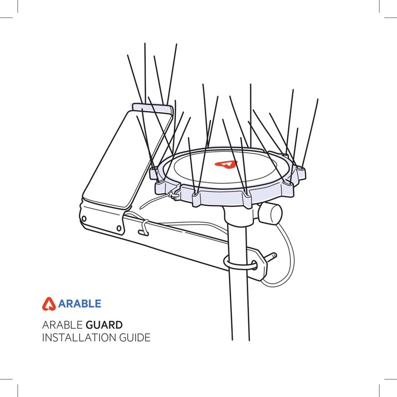
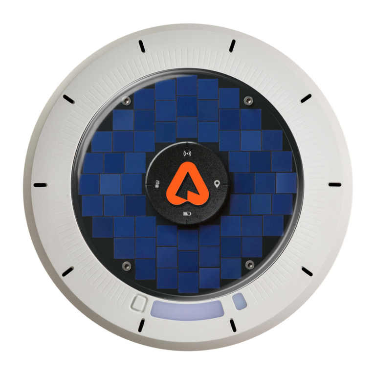
ARABLE Mark 3 User manual

Arable Mark 3
Quick Start Guide
In the box:
●Mark 3 Device
●Solar Panel
●Solar Panel Knob
●Cellular Antenna
●BLE Antenna
●Power Charging Cable (USB to M8 Connector)
●4” (10cm) Bird Spikes [Qty: 5]
●2.75” (7cm) Bird Spikes [Qty: 21]
●8” (20cm) Zip Ties [Qty: 5]
Step 1: Pre-deployment
Connect your device to a
charger
Note:
Using 10W+ charger, charging to full
battery can take up to 7 hours from
empty. If using a 5W charger,
charging to full battery can take up
to 14 hours.
Charge until your device’s lightning bolt icon turns white by plugging
your charging cord into the provided USB-C converter or directly
into a 10W+ wall charger (not included). The lightning bolt icon will
be green while charging. Reattach the charging cap prior to
deployment.
www.arable.com ○ support@arable.com ○ 510-992-4095 Pg. 1

Step 2:
Ensure the solar panel is
attached to the Mark 3
Note:
For maximum charging, face the
solar panel towards the equator. The
panel may be faced up to 90 degrees
away from the equator if needed.
First, attach the cable from the panel to the Mark 3 cable. You will
hear a snap. Insert the connected cables in the solar panel cavity.
From top→down, slide the groove of the panel down the Mark 3
casing. There will be a soft click.
If the panel is properly connected and in sufficient sunlight, you will
see a green light at the lightning bolt icon. Ensure that the provided
knob is screwed into the side to secure the solar panel in place.
Do not proceed until you have successfully attached the
solar panel to the Mark 3.
Step 3:
Attach antennas
Attach the Cellular and Bluetooth antennas to their respective ports
on the underside of the Mark 3, matching the icons on the antennas
to the icons on the Mark.
www.arable.com ○support@arable.com ○510-992-4095 Pg.2

Step 4:
Deploy your Mark 3
Note: It may take 5 to 10 minutes for
lights to stop flashing during the
deployment sequence. The Additional
Sensor light will stay amber if there is
no connection.
Hold the power button for 2 seconds to turn ON the device and sync
with the Arable system. Each time you do this you will create a
“deployment”. The deployment sequence will begin with flashing blue
lights that will turn solid green when complete. For more scenarios,
see the Deployment Outcomes section below.
Step 5:
Attach bird spikes
Insert the bird spikes into the holes around the perimeter of the top
of the Mark. The four longer spikes with the orange rubber ends are
to be placed at the 12, 3, 6, and 9 o’clock positions. Firmly push in.
Step 6:
View your data in the Arable
web or mobile application
Note: It will take up to an hour to
populate the initial measured data in
the apps and the first battery
percentage may not show 100% even if
fully charged.
Use your login credentials to view data from your Mark 3(s) on
app.arable.com. New deployments will appear in the “Unassigned
Device” list of the Map page in Arable Web. In Arable Mobile a red
dot will show up in the “Weather List” menu icon. Find your device by
device ID and deployment timestamp in these lists and then name
your deployment/site.
www.arable.com ○support@arable.com ○510-992-4095 Pg.3

Deployment Outcomes
Successful
deployment
Once the activation process has completed, the status of each light icon will
remain steady for 10 seconds before every light, except for the lightning bolt,
goes out. A successful deployment will display green lights.
Failed
deployment
The light icons will flash red for 30 seconds if a deployment has failed. Any
failure is represented by its icon flashing red:
Battery too low to connect → Take inside to charge.
Sensor Failure → Contact Arable
Connectivity to Server → Move location or contact Arable.
Additional Sensors connected but no communication → Contact Arable
Actions you can
take
Status Check → Quick tap and release of the Power button.
Undeployed State:
Battery light flashes green → Ready to redeploy
Battery light flashes red → Recharge
Deployed State:
Steady green lights → Operating normally
Battery light red → Recharge
Sensors light red → Sensor failed / Contact Arable
Connectivity light red → Bad Connection / Move Location
Additional Sensor light amber → No sensor connected
Additional Sensor light green → 1 sensor connected
Additional Sensor light purple → 2+ sensors connected
To Deploy → 2 second press, hold & release power button.
Blinking blue lights turn green→ Successful deployment
Blinking blue lights turn red → Failed deployment
**The connectivity icon may blink for up to 5 to 10 minutes
while the Mark establishes a connection with the cell tower.
Note: The Mark 3 must be deployed in outdoor/open-air locations to
establish a GPS location and show up in the apps.
To Undeploy → 2 second press, hold & release power button.
Blinking amber lights turn off when complete
Note: Undeployment can take up to 10 minutes if low/no network coverage
Hard Reset → 15 second hold and release of the power button.
Battery light flashes amber and turns off when rebooting
Perform Status Check to confirm new deployment
Lightning bolt LED
Green while charging and white when fully charged.
Orientation
Your Mark 3 should be deployed 3-4 feet above the maximum expected height
of your crop canopy. The “A” in the Arable logo should point +/-90° towards the
equator.
www.arable.com ○support@arable.com ○510-992-4095 Pg.4

Sensor Guide
Meaning of Sensors
(from Left to Right)
Battery
Green → Sufficient power to deploy
Red → Battery is too low to connect
Internal Sensor
Green→ Sensors are all in working condition
Red → One or more sensors have failed
Connectivity → Device has connected to the Arable system.
*Additional Sensors→ Status of additional attached sensors.
Amber→ No sensors attached
Green → One sensor attached
Purple → Two or more sensors attached
Lightning Bolt → Charging status
Green → Charging
White → Fully charged
*It takes 10-15 seconds for the light to change color after connecting
any additional sensor.
www.arable.com ○support@arable.com ○510-992-4095 Pg.5

Accessory Installation
Instructions
Mark 3 Anemometer
In the box:
Mark 3 Anemometer
(preassembled)
Step 1: Twist and lock Mark 3 to the
Anemometer base
Using the equipment provided, twist the Mark 3 so that the
anemometer arm aligns 90° to the Mark 3 solar panel.
Step 2: Connect Anemometer cable to Mark 3
After attaching your Mark 3, connect the blue M8 cable from the
anemometer to the blue port on Mark 3. Remember to save the black
cap for off-season storage.
Step 3: Install Mark 3 assembly to the pole
Tighten the top knob and mount the Mark 3 to the top of the
telescoping pole. Turn the Mark 3 in a position that is facing the
equator +/- 90°. Tighten the bottom knob.
Step 4: Perform status check
Quick tap (1 second) & release the power button.
Additional Sensor light amber → No sensor connected
Additional Sensor light green → 1 sensor connected
Additional Sensor light purple → 2+ sensors connected
Mark 3 Hub Adapter
In the box:
Mark 3 Hub Adapter
Pole clip (bolt & lock nut)
8” (20cm) zip ties
Step 1: Connect Hub Adapter
Connect the orange M12 cable to the orange port on the Mark 3.
Remember to save the black cap for off-season storage.
Step 2: Mount Hub Adapter & cable to the pole
Use the pole clip (or zip ties) to attach the Hub Adapter to the pole.
Fasten the cable to the pole using the additional zip ties.
Step 3: Attach external sensor cables
Soil Moisture (brown SDI-12 connector)
Pressure Switch (yellow analog connector)
I/O expansion (purple RS232/485 connector)
Step 4: Perform status check
Quick tap (1 second) & release the power button.
Additional Sensor light amber → No sensor connected
Additional Sensor light green → 1 sensor connected
Additional Sensor light purple → 2+ sensors connected
www.arable.com ○support@arable.com ○510-992-4095 Pg.6

FCC Statement
Interference Statement:
This device complies with Part 15 of the FCC Rules. Operation is subject to the following two conditions: (1) This device may not cause harmful interference, and (2) this device
must accept any interference received, including interference that may cause undesired operation.
This equipment has been tested and found to comply with the limits for a Class B digital device, pursuant to Part 15 of the FCC Rules. These limits are designed to provide
reasonable protection against harmful interference in a residential installation. This equipment generates, uses and can radiate radio frequency energy and, if not installed and
used in accordance with the instructions, may cause harmful interference to radio communications. However, there is no guarantee that interference will not occur in a
particular installation. If this equipment does cause harmful interference to radio or television reception, which can be determined by turning the equipment off and on, the user
is encouraged to try to correct the interference by one of the following measures:
●Reorient or relocate the receiving antenna.
●Increase the separation between the equipment and receiver.
●Connect the equipment into an outlet on a circuit different from that to which the receiver is connected.
●Consult the dealer or an experienced radio/TV technician for help.
FCC Caution: Any changes or modifications not expressly approved by the party responsible for compliance could void the user's authority to operate this equipment.
This transmitter must not be co-located or operating in conjunction with any other antenna or transmitter.
Radiation Exposure Statement:
This equipment complies with FCC radiation exposure limits set forth for an uncontrolled environment. This equipment should be installed and operated with a minimum
distance of 20 cm between the radiator & your body.
Industry Canada Statement
CAN ICES3 (B)/NMB3 (B)
This device complies with ISED’s license-exempt RSSs. Operation is subject to the following two conditions: (1) This device may not cause harmful interference, and (2) this
device must accept any interference received, including interference that may cause undesired operation.
Le présent appareil est conforme aux CNR d’ ISED applicables aux appareils radio exempts de licence. L’exploitation est autorisée aux deux conditions suivantes : (1) le dispositif
ne doit pas produire de brouillage préjudiciable, et (2) ce dispositif doit accepter tout brouillage reçu, y compris un brouillage susceptible de provoquer un fonctionnement
indésirable.
Radiation Exposure Statement:
This equipment complies with ISED radiation exposure limits set forth for an uncontrolled environment. This equipment should be installed and operated with greater than 20cm
between the radiator & your body.
Déclaration d'exposition aux radiations:
Cet équipement est conforme aux limites d'exposition aux rayonnements ISED établies pour un environnement non contrôlé. Cet équipement doit être installé et utilisé à plus de
20 cm entre le radiateur et votre corps.
CE Statement
This device complies with Directive 2014/53/EU and UK Radio Equipment Regulations 2017 SI 2017/1206. issued by the Commission of the European Community.
Declaration of Conformity
Hereby, Arable Labs Inc. declares that the radio equipment type Arable Mark 3 is in compliance with Directive 2014/53/EU and UK Radio Equipment Regulations 2017 SI
2017/1206.
The full text of the EU declaration of conformity is available at the following internet address: arable.com
The frequency and maximum transmitted power in the EU are listed as below.
●2402~2480MHz: 9.36 dBm
This equipment should be installed and operated with a minimum distance of 24 cm between the radiator and your body.
Supported bands
●LTE-M: B1/B2/B3/B4/B5/B8/B12/B13/B18/B19/B20/B25/B26/B27/B28/B66/B85
●NB-IoT: B1/B2/B3/B4/B5/B8/B12/B13/B18/B19/B20/B25/B28/B66/B71/B85
●2G: 850/900/1800/1900 MHz
Detachable Antenna Usage
This radio transmitter [IC: 29735-MARK3] has been approved by Innovation, Science and Economic Development Canada to operate with the antenna types listed below, with
the maximum permissible gain indicated. Antenna types not included in this list that have a gain greater than the maximum gain indicated for any type listed are strictly
prohibited for use with this device.
Le présent émetteur radio [IC: 29735-MARK3] a été approuvé par Innovation, Sciences et Développement économique Canada pour fonctionner avec les types d'antenne
énumérés ci-dessous et ayant un gain admissible maximal. Les types d'antenne non inclus dans cette liste, et dont le gain est supérieur au gain maximal indiqué pour tout type
figurant sur la liste, sont strictement interdits pour l'exploitation de l'émetteur.
Manufacturer
Model
Antenna Type
Max Gain (dBi)
Impedance (Ω)
Grand-Tek
103DG00000160
Dipole
2.4
50 ohm
Grand-Tek
1036G00000970
Dipole
3.2
50 ohm
Anatel Statement
Este equipamento não tem direito à proteção contra interferência prejudicial e não pode causar interferência em sistemas devidamente autorizados – Para maiores informações,
consulte o site da Anatel – https://www.gov.br/anatel/pt-br/
Incorpora produto homologado pela Anatel sob número 05174‐21‐07968
International Mobile Equipment Identity (IMEI) Statement
The unique IMEI number assigned to the Mark 3 can be found on the product label.
www.arable.com ○support@arable.com ○510-992-4095 Pg.7
Table of contents
Other ARABLE Irrigation System manuals