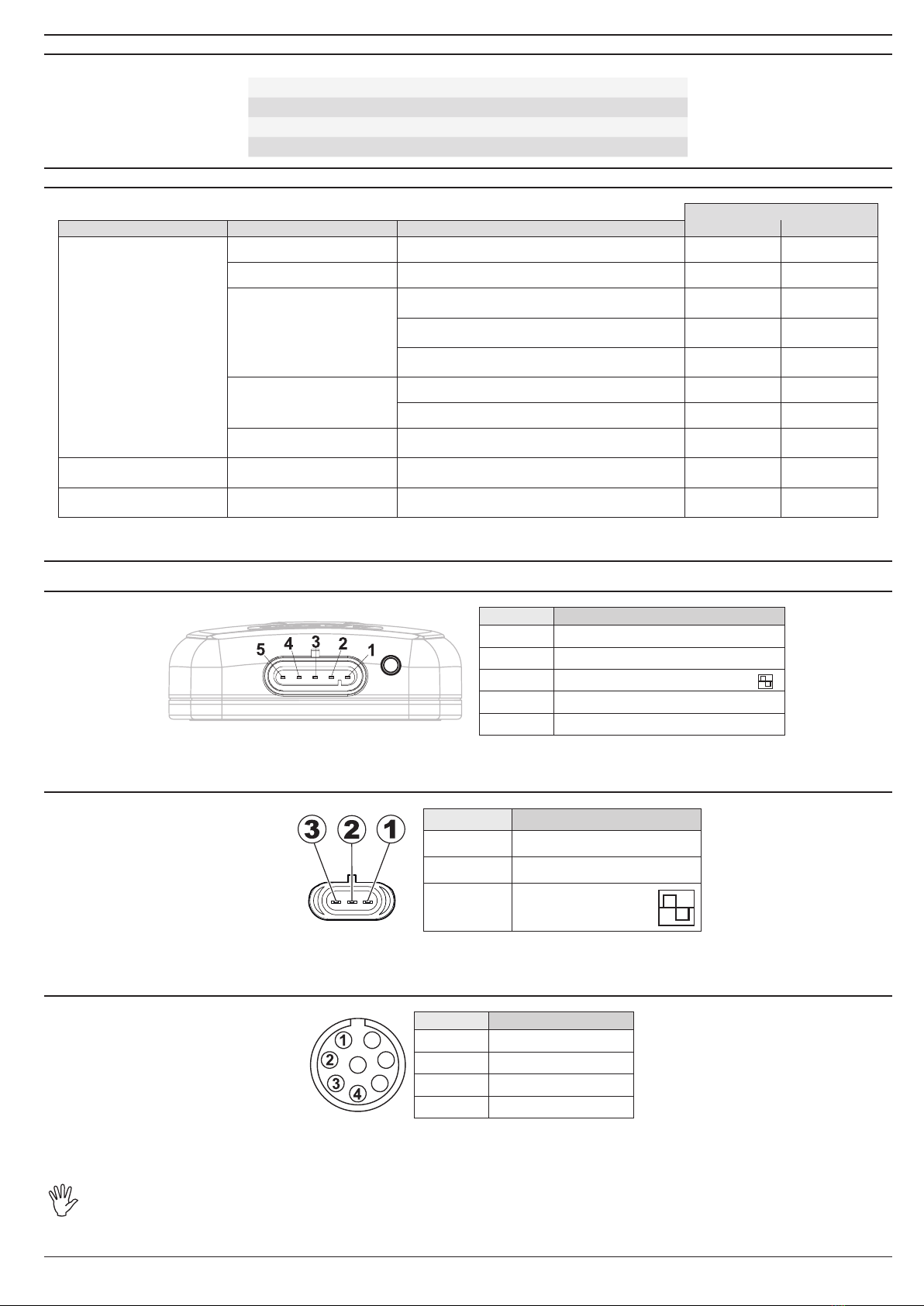
ARAG ATLAS 100 Quick start guide

INSTALLATION, USE AND MAINTENANCE
46701651- GPS SPEED SENSOR
46701652- GPS SPEED SENSOR
FOR BRAVO 180S/300S

2
This manual is an integral part of the equipment to which it refers and must accompany the equipment in case of sale or change of ownership. Keep it for any future
reference; ARAG reserves the right to modify product specications and instructions at any moment and without notice.
LEGEND OF SYMBOLS
=Generic danger
=Warning
1 Intended use...................................................................................................................................................................................................................3
2 FCC standards................................................................................................................................................................................................................3
3 Precautions.....................................................................................................................................................................................................................3
4 Package content.............................................................................................................................................................................................................3
5 Dimensions.....................................................................................................................................................................................................................4
6 Positioning......................................................................................................................................................................................................................4
7 Wiring connections........................................................................................................................................................................................................6
7.1 General precautions for a correct harness position .........................................................................................................................................................6
7.2 Wiring harness connection...............................................................................................................................................................................................6
8 LED signals.....................................................................................................................................................................................................................7
9 Troubleshooting .............................................................................................................................................................................................................7
9.1 Connector connection ......................................................................................................................................................................................................7
10 Technical data ................................................................................................................................................................................................................8
11 End-of-life disposal........................................................................................................................................................................................................8
12 Warranty terms...............................................................................................................................................................................................................8
13 EC declaration of conformity.......................................................................................................................................................................................8
CONTENTS

3
1 INTENDED USE
ATLAS 100 is a GPS speed sensor compatible with signals coming from GPS and GLONASS systems, which allows measuring the speed of a
farming machine during operation.
ATLAS100 outputs a signal having a frequency proportional to farming machine speed (please refer to section 10 “Technical data” for further details).
ARAG devices provided with input for speed sensor can rely on this information after connection to ATLAS 100 sensor by means of the suitable
cable supplied in the package.
Kit code 46701652, “Speed sensor for Bravo 180S/300S” is equipped with a serial port used for position (GGA) and speed (VTG) information, at 5
Hz, according to NMEA standard. BRAVO 300S and BRAVO 180S computers can be connected using the cable supplied with the system, they rely
on the speed information to adjust product quantity and on position information to track the job carried out
The equipment is designed and manufactured according to European directives and international standards:
2014/53/UE (RED), 2014/30/UE (EMC), CFR47 Part 15 Subpart B - Unintentional Radiators (FCC-USA) e ICES-003 Issue 5 - August
2012 - Information technology Equipment (ITE) - Limits and Methods of Measurement (Canada).
2 FCC STANDARDS
This GPS speed sensor complies with the limits provided for class B digital devices, in accordance with CFR47 part 15, subpart B of FCC standards.
These limits provide for parameters for a reasonable protection against harmful interferences.
The ATLAS 100 speed sensor generates, uses and can emit radio frequency energy and, if not correctly installed and used, may cause harmful
interferences to the communications of radio frequency devices. Nevertheless, we do not guarantee that, in particular circumstances, interferences
interference by using one or more of the following measures:
• Re-orient or reposition the sensor.
• Increase the distance between the disturbed and/or malfunctioning device and the sensor.
3 PRECAUTIONS
• Do not aim powerful water jets at the equipment when cleaning the device or the farming machine on which it is installed.
• Do not use solvents or fuel to clean the case outer surface.
• In case of voltaic arc welding, unplug connector from the device.
• Only use ARAG genuine spare parts and accessories.
4 PACKAGE CONTENT
Code
Speed sensor Instruction manual
Connection cable
for output in frequency
Connection cable
for computer

4
5 DIMENSIONS
Fig. 1
CONTINUES
6 POSITIONING
clearance height of the vehicle.
-
clined surface: therefore we advise against using it to operate on inclined surfaces (hill) if the system as a whole is not provided
with other solutions able to measure and correct such position errors.
GPS speed sensor installation:
There are certain essential requirements to be met when installing the sensor on the farming machine:
it must be mounted on the highest point of the vehicle (including the trailer); angle of reception in the skyward direction should be as wide as possible.
Fig. 2 Fig. 3

5
The sensor must be installed on vehicle longitudinal axis and positioned so that the harness is routed in the direction opposite to the motion (Fig. 5).
Fig. 4
• GPS speed sensor fastening:
The sensor is provided with 3 magnets on the bottom side and must be fastened to a level metallic surface (for instance: the roof of the farming machine).
In case the roof is made of plastic, use a metal base (not supplied) fastened to farming machine chassis.
We recommend checking periodically the metal base
The lower part of speed sensor also features four anti-rotation recesses (Fig. 6) which can be used to fasten the antenna or to avoid accidental
misplacing of the sensor due to shocks or vibrations.
If the sensor is fastened using the anti-rotation recesses, we recommend using DIN 7505 4x10 mm self-tapping screws, paying utmost attention to
magnets
anti-rotation recesses
Fig. 5
Fig. 6 - Dimensions of anti-rotation recesses

6
7 WIRING CONNECTIONS
• Use the supplied harnesses only.
• Take care not to break, pull, tear or cut the cables.
• Use of unsuitable cables not provided by ARAG automatically voids the warranty.
• ARAG is not liable for any damage to the equipment, persons or animals caused by failure to observe the above instructions.
• ATLAS 100 speed sensor is intended to be electrically powered by other devices. In this case it is necessary to install a 0.5A
fuse on power positive cable.
7.1 General precautions for a correct harness position
• Securing the cables:
- fasten the harnesses so that they do not interfere with moving parts;
- route the harnesses so that they cannot be damaged or broken by machine movements or twisting.
• Fitting the cables to the connection points:
- Do not force the connectors by pushing too hard or bending them: the contacts may be damaged and device operation may be compromised.
Device name
WARNING: MAKE SURE THE YELLOW SEAL IS PROPERLY SEATED IN THE CONNECTOR: ONE LIP OF THE SEAL OUT OF ITS
SEAT OR SEAL WRONG INSTALLATION COULD COMPROMISE SEALING AND PROTECTION AGAINST WEATHER CONDITIONS!
Use ONLY the cables and accessories indicated in the catalog, having technical features suitable for the use to be made of
them.
7.2 Wiring harness connection
Connect the 5-pole Superseal connector of the harness to speed sensor, pushing it all the way down until engaging the retaining tooth.
Do not twist or excessively bend the cable during positioning.
Fig. 7
Fig. 8
To remove the connector from the speed sensor, insert a screwdriver (or similar tool) in the relevant seat
onto the connector, slightly raise the tab (1) and slide out the connector (2).

7
8 LED SIGNALS
The LED on the rear side of ATLAS 100 sensor indicates receiver operation by changing color and status:
OFF
GREEN : waiting for GPS data reception
GREEN steady on: correct reception of GPS data
: power supply voltage incompatible with the permitted one
9 TROUBLESHOOTING
APPLICATION
MALFUNCTION CAUSE REMEDY Code 46701651 Code 46701652
The ATLAS 100 sensor does not
output speed information
No power supply Check connections and ensure that LED on device is ON
Device not connected Check connections
Connection not set correctly
Ensure the proper speed source is selected on the menu
of the device connected to ATLAS 100
Ensure the proper serial port is set on the menu of the
device connected to ATLAS 100
Ensure the proper conversion constant is set on the menu
of the device connected to ATLAS 100
Device waiting for satellite signal
Change sensor position
Speed not within working limits Increase or decrease working speed to return within
allowed range.
The device outputs wrong speed
information Connection not set correctly Ensure the proper conversion constant is set on the menu
of the connected device
Power supply voltage too low or
too high Check power supply voltage
9.1 Connector connection
9.1.1 Pinout of Superseal connector on ATLAS 100 sensor
Position* Connection of
1GND
2
3OUT (Output in square wave frequency)
4
5
*: contacts on antenna connector side
9.1.2 Pinout of cable connector for output in frequency (kit code 46701651)
Position* Connection of
GND
OUT (output in square
wave frequency)
*: contacts on connector side (external)
9.1.3
Position* Connection of
1GND
2
3
4
*: contacts of connector on welding side
ARAG is not liable for any damage to the system, persons, animals or property caused by speed sensor wrong or unsuitable
assembly. Failure to observe the above instructions automatically voids the warranty.

8
10 TECHNICAL DATA
PERFORMANCE:
Number of receiver channels ............................
Systems used:................................................... GPS & GLONASS
Refresh rate: .....................................................
Start time: .........................................................
ELECTRICAL FEATURES
Power supply voltage ........................................
Consumption .....................................................
Protection against polarity inversion ................. Yes
Protection against short-circuit.......................... Yes
Digital output:
Type:.......................................
Maximum current:...................
Conversion constant:..............
Working range ........................
Serial port:
Type:.......................................
..........................
Protocol: .................................
Messages: ..............................
Operating temperature ...................
Storage temperature ......................
Protection rating .............................
PHYSICAL FEATURES
Weight (sensor only): ........................................
11 END-OF-LIFE DISPOSAL
Dispose of the system in compliance with the established legislation in the country of use.
12 WARRANTY TERMS
1. ARAG s.r.l. guarantees this apparatus for a period of 360 days (1 year) from the date of sale to the client user (date of the goods delivery
note).
The components of the apparatus, that in the unappealable opinion of ARAG are faulty due to an original defect in the material or produc-
tion process, will be repaired or replaced free of charge at the nearest Assistance Center operating at the moment the request for inter-
vention is made. The following costs are excluded:
- disassembly and reassembly of the apparatus from the original system;
- transport of the apparatus to the Assistance Center.
2. The following are not covered by the guarantee:
- damage caused by transport (scratches, dents and similar);
alterations resulting from environmental, climatic or other conditions;
- damage due to the use of unsuitable chemical products, for spraying, watering, weedkilling or any other crop treatment, that may damage
the apparatus;
- incorrect installation and regulation;
- anything that can be considered to be normal wear and tear;
3. Repairing the apparatus will be carried out within time limits compatible with the organizational needs of the Assistance Center.
No guarantee conditions will be recognized for those units or components that have not been previously washed and cleaned to remove
residue of the products used;
4. Repairs carried out under guarantee are guaranteed for one year (360 days) from the replacement or repair date.
5. ARAG will not recognize any further expressed or intended guarantees, apart from those listed here.
No representative or retailer is authorized to take on any other responsibility relative to ARAG products.
The period of the guarantees recognized by law, including the commercial guarantees and allowances for special purposes are limited, in
length of time, to the validities given here.
6. The parts replaced under guarantee remain the property of ARAG.
7. All safety information present in the sales documents regarding limits in use, performance and product characteristics must be transferred
to the end user as a responsibility of the purchaser.
8. Any controversy must be presented to the Reggio Emilia Law Court.
13 EC DECLARATION OF CONFORMITY
The declaration of conformity is available at the website www.aragnet.com, in the relevant section.

9
Page intentionally
left blank

D20371_GB-m01 11/2017
Via Palladio, 5/A
42048 RUBIERA (Reggio Emilia) - ITALY
Tel. +39 0522 622011
Fax +39 0522 628944
http://www.aragnet.com
Only use genuine ARAG accessories or spare parts to make sure manufacturer guaranteed safety conditions are maintained in time. Always refer to ARAG spare
parts catalog.
Table of contents
Other ARAG Accessories manuals