8
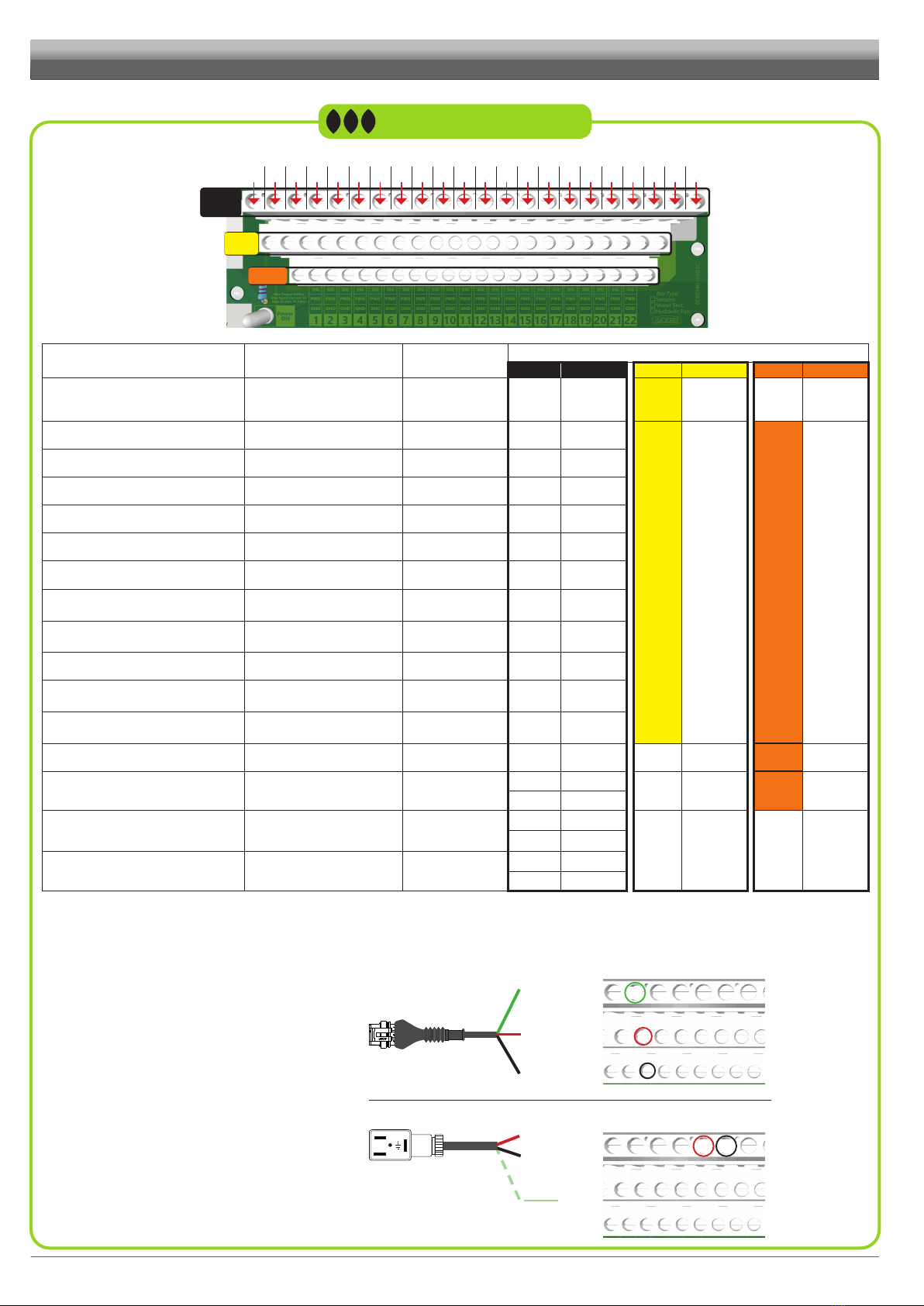
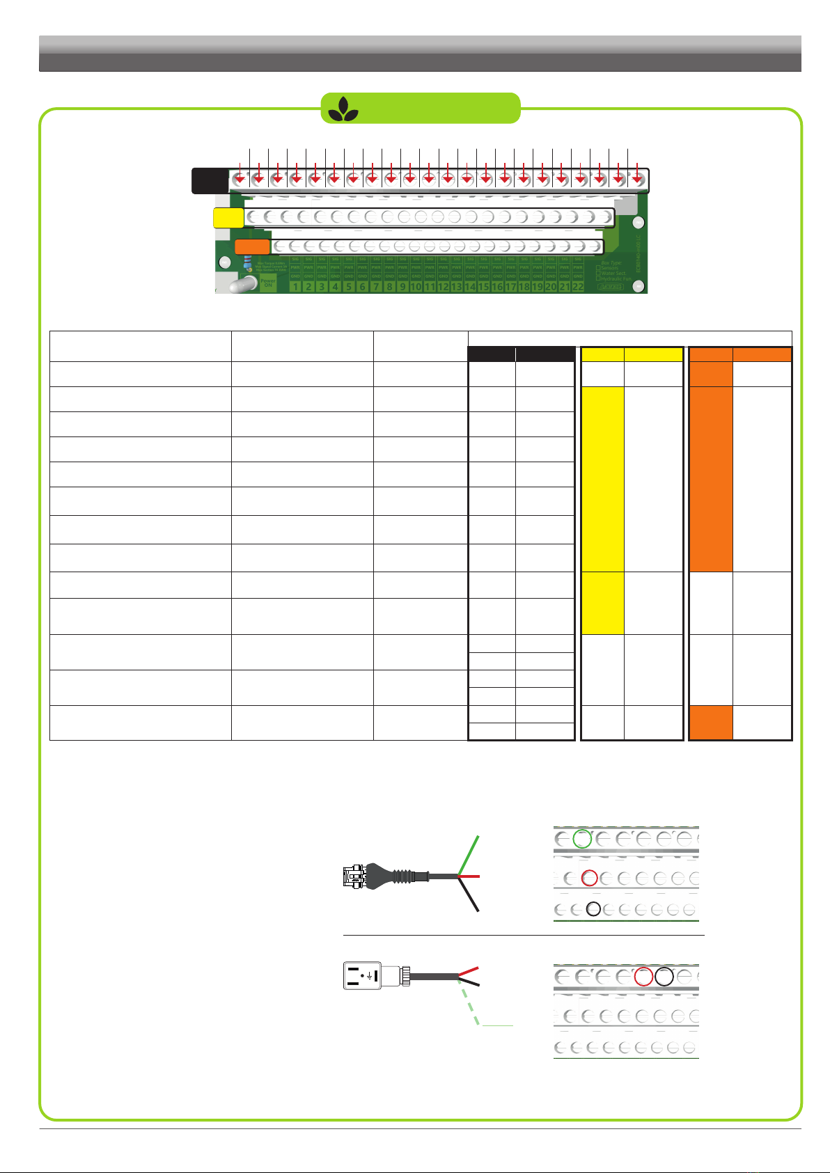
CONFIGURATION - AIR SEEDER
n.c.: not connected
#SIG
PWR
GND
1 9 175 13 213 11 197 152 10 186 14 224 12 208 16
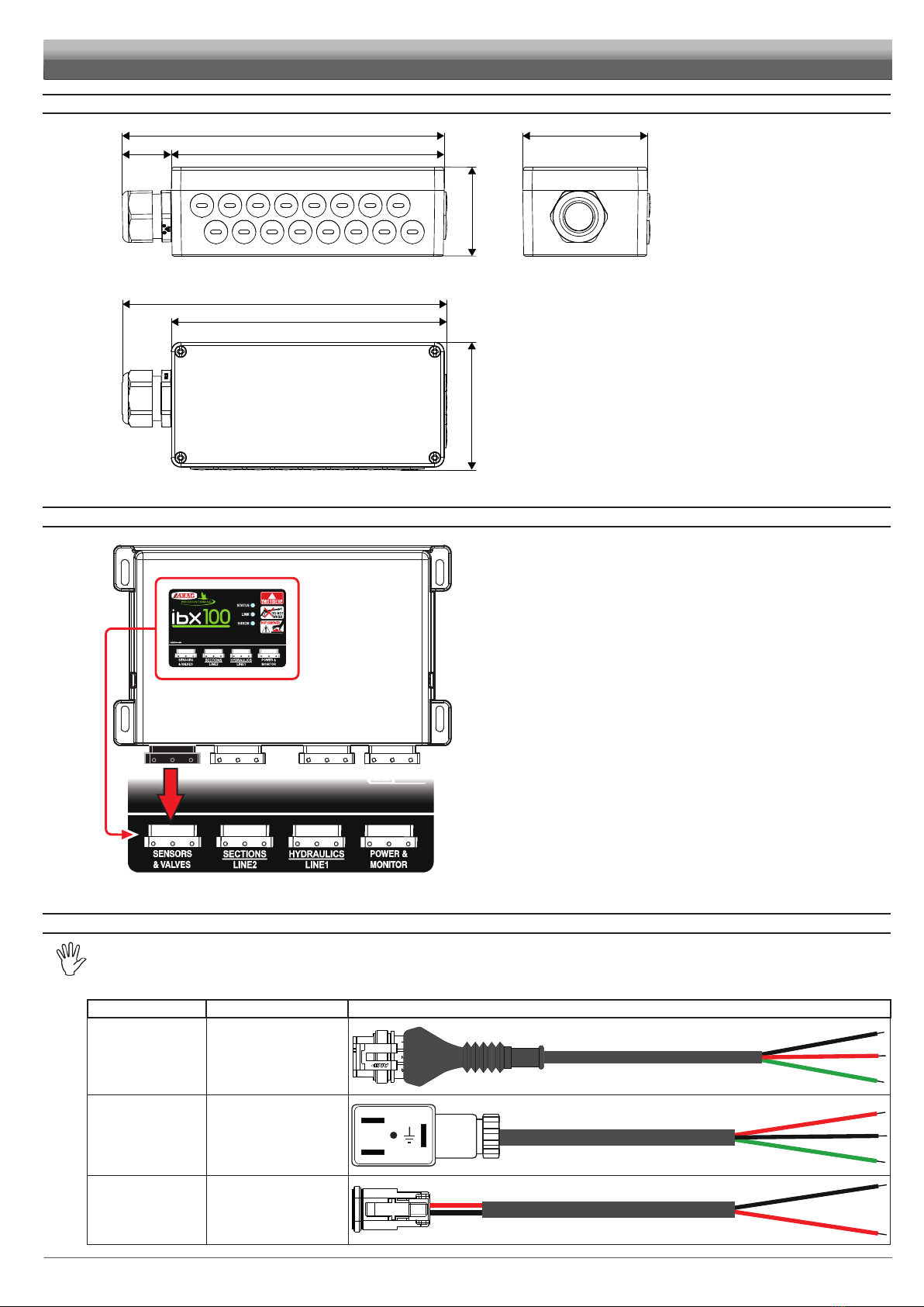
E.g.: CABLE CODE 4621AA10000.100 with speed signal
#SIG
PWR
GNDPIN 1
PIN 2
PIN 3 11
E.g.: CABLE CODE 8650900.140 for proportional valve control
#SIG
PIN 2
PIN 3
PIN 1 1817
SIGNAL TYPE OF SENSOR
[ARAG CODE]
CABLE
ADAPTER
CONNECTION OF CABLES SENSOR / VALVES (Pin)
Clamp Wire Clamp Wire Clamp Wire
PRESSURE
Analogue sensor
4621AA10000.100 #SIG 1GREEN PWR RED n.c. BLACK
MACHINE STATUS Digital sensor
4621AA10000.100 #SIG 7GREEN
PWR RED GND BLACK
TANK 1 LEVEL Capacitive sensor
4621AA10000.100 #SIG 15 GREEN
TANK 2 LEVEL Capacitive sensor
4621AA10000.100 #SIG 16 GREEN
TANK 3 LEVEL Capacitive sensor
4621AA10000.100 #SIG 8GREEN
TANK 4 LEVEL Capacitive sensor
4621AA10000.100 #SIG 10 GREEN
SPEED Digital sensor
4621AA10000.100 #SIG 11 GREEN
RPM 1 Digital sensor
4621AA10000.100 #SIG 14
(**) GREEN
FLOWRATE Digital sensor
4621AA10000.100 #SIG 12
(**) GREEN
FAN ROTATION Digital sensor
4621AA10000.100 #SIG 13 GREEN
TANK 1 LEVEL - ADDITIONAL Capacitive sensor
4621AA10000.100 #SIG 12
(**) GREEN
TANK 2 LEVEL - ADDITIONAL Capacitive sensor
4621AA10000.100 #SIG 14
(**) GREEN
CALIBRATION BUTTON Button
-#SIG 9contact 2 n.c. n.c. GND contact 1
CAN BUS-MOTOR COMMUNICATION - [not supplied] #SIG 21 can_L n.c. n.c. GND gnd
#SIG 22 can_H
PROPORTIONAL VALVE CONTROL
Motorized proportional valve
[ARAG SERIES 863T - 873T
8650900.140
#SIG 17 RED
n.c. n.c. n.c. n.c.
#SIG 18 BLACK
MAIN VALVE CONTROL Motorized ON-OFF valve
8650900.140 #SIG 19 RED
#SIG 20 BLACK
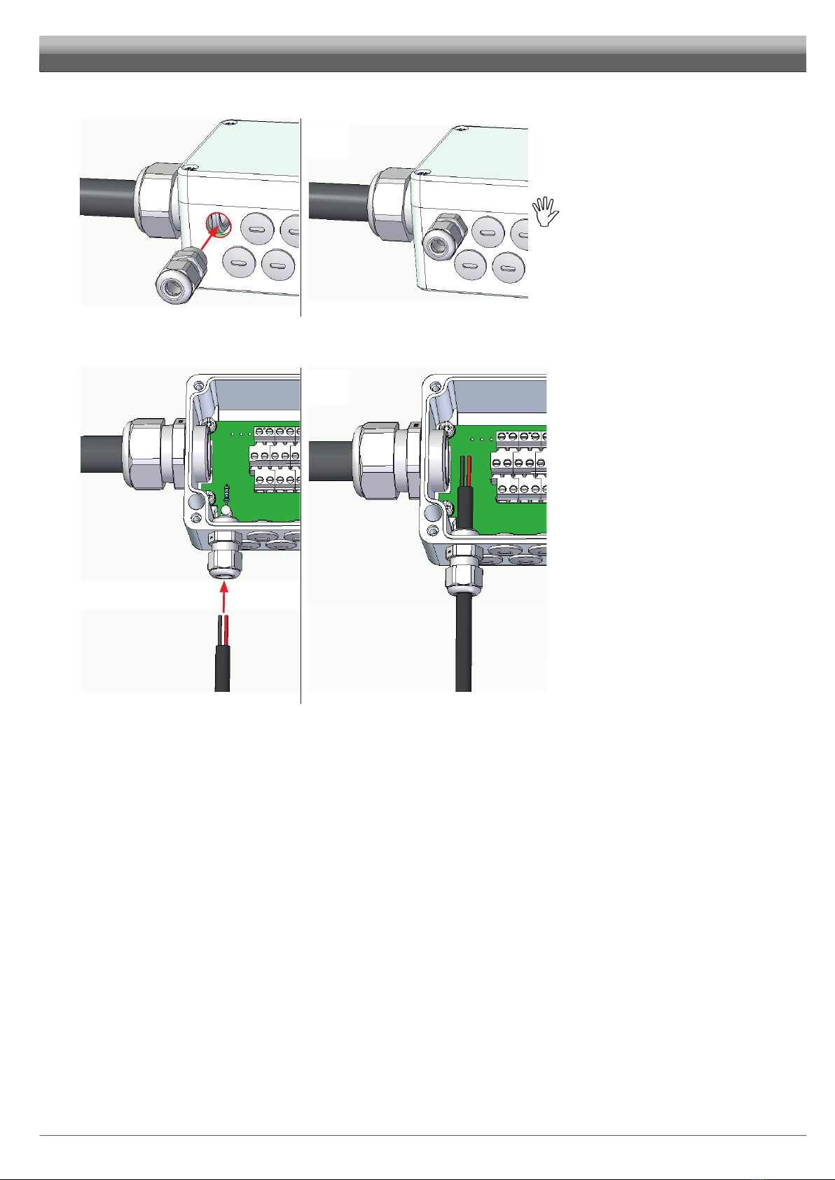
Below are some examples of
connection of the adapter cable wires
to the terminal board of the printed
circuit board: