ARAG MP Series Instruction Manual

CODE
97005001
PUMP MSP400 5S T7F-T6F
MSP MULTISTAGE CENTRIFUGAL PUMP MSP400
With hydraulic motor
01.15
01.20
01.25
01.28
01.09
01.06
01.05
01.02
01.24
01.19
01.12
01.18
01.14
970000.510
01.06 01.04
01.11
01.17
01.22
01.16
01.27
01.26
01.18
01.19 01.24
01.21
01.23
01.10
01.18
01.21
01.24
01.13
05
01.07
01.03
01.08 03 04 02
REFERENCE CODE DESCRIPTION REFERENCE CODE DESCRIPTION
01.02 970050.040 TUBO ESTERNO POMPA MSP400 5S 01.18 B12251 SELF-LOCKING NUT M8 INOX UNI7474
01.03 970000.061 RADIAL BALL BEARING 6305-2RS 01.19 B202H0 FLAT WASHER 8,4X15X1,5 INOX
01.04 970000.070 MECHANICAL SEAL 01.20 B202J0 FLAT WASHER D.10,5X21X2 * INOX
01.05 970000.081 BOCCOLA IGUS XSM-1214-12 01.21 B222H0 WASHER GROVER D 8,2 INOX UNI1751
01.06 G11093V OR 3,00X114,50 ORM1145-30 VITON 01.22 G11015V OR 1,78X12,42 VITON
01.07 B332Z2 SEEGER INTERNO D.62 INOX UNI7437 01.23 V1C25L VITE TCEI 8X 30 INOX UNI5931
01.08 B322X1 SEEGER ESTERNO D.25 INOX UNI7435 01.24 V1M25K SCREW TE 8X25 INOX
01.09 B12261 DADO AUTOBLOCC. M10 INOX UNI7474 01.25 970000.115 FLANGIA ASP. T7F POMPA MSP400
01.10 970000.060 BEARING SUPPORT PUMP MP400 01.26 970000.110 FLANGIA MAND. T6F POMPA MSP400
01.11 970000.080 DISTANZIALE INTERNO POMPA MSP400 01.27 010006 FORK D.4 DIST.47
01.12 970050.090 STAFFA FISSAGGIO POMPA MSP400 5S 01.28 010007 FORK D.5 DIST.59
01.13 970050.050 ALBERO POMPA MSP400 5S COMPLETO 02 V1C26M VITE TCEI 10X 35 INOX UNI5931
01.14 970000.082 DADO SERRAGGIO GIRANTI POMPA MSP400 03 B12261 DADO AUTOBLOCC. M10 INOX UNI7474
01.15 970050.091 TIRANTE 10X268 INOX 04 B222J0 WASHER GROVER 10,5X17,5X2,2 * INOX
01.16 970000.084 TAPPO 1/4" M 05 9700000.100 MOTOR 11.2 CC
01.17 970000.083 ESTRATTORE ANELLO TENUTA MECCANICA
Powered by TCPDF (www.tcpdf.org)
Page 1 of 1

970050XX
CENTRIFUGAL PUMP SERIES MP
INSTALLATION AND MAINTENANCE

LEGEND OF SYMBOLS
=Generic danger
=Warning
CONTENTS
Legend of symbols ................................................................................................................................................................................. 2
1 Product description ................................................................................................................................................................................ 3
2 Intended use............................................................................................................................................................................................ 3
3 Package content...................................................................................................................................................................................... 3
4 Versions, codes and operating curves ................................................................................................................................................. 3
4.1 Versions and codes ........................................................................................................................................................................ 3
4.2 Operating curves ............................................................................................................................................................................ 4
4.2.1 How to read the diagrams: ............................................................................................................................................................. 4
4.2.2 Curves ............................................................................................................................................................................................ 4
5 Installation............................................................................................................................................................................................... 6
5.1 Example of a typical system composition ....................................................................................................................................... 6
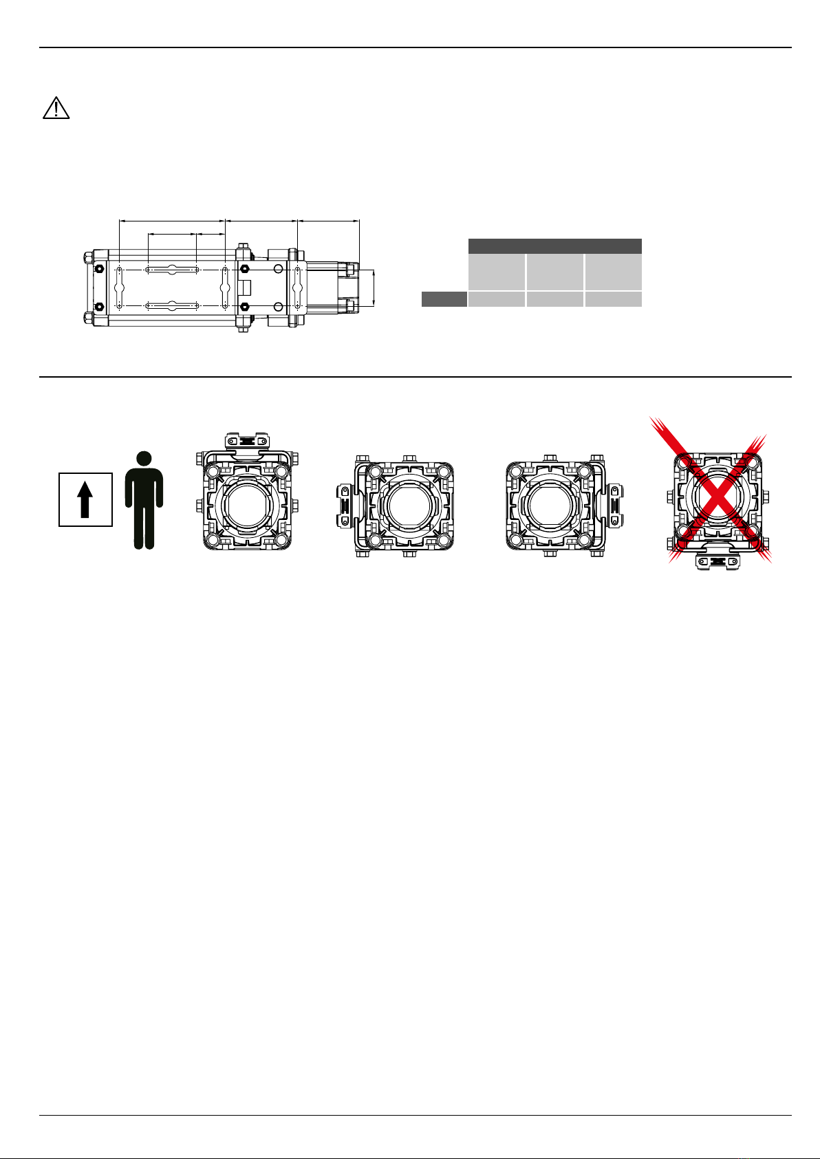
5.2 Dimensions (mm)............................................................................................................................................................................ 6
5.3 Attachment...................................................................................................................................................................................... 7
5.4 Pump assembly direction................................................................................................................................................................ 7
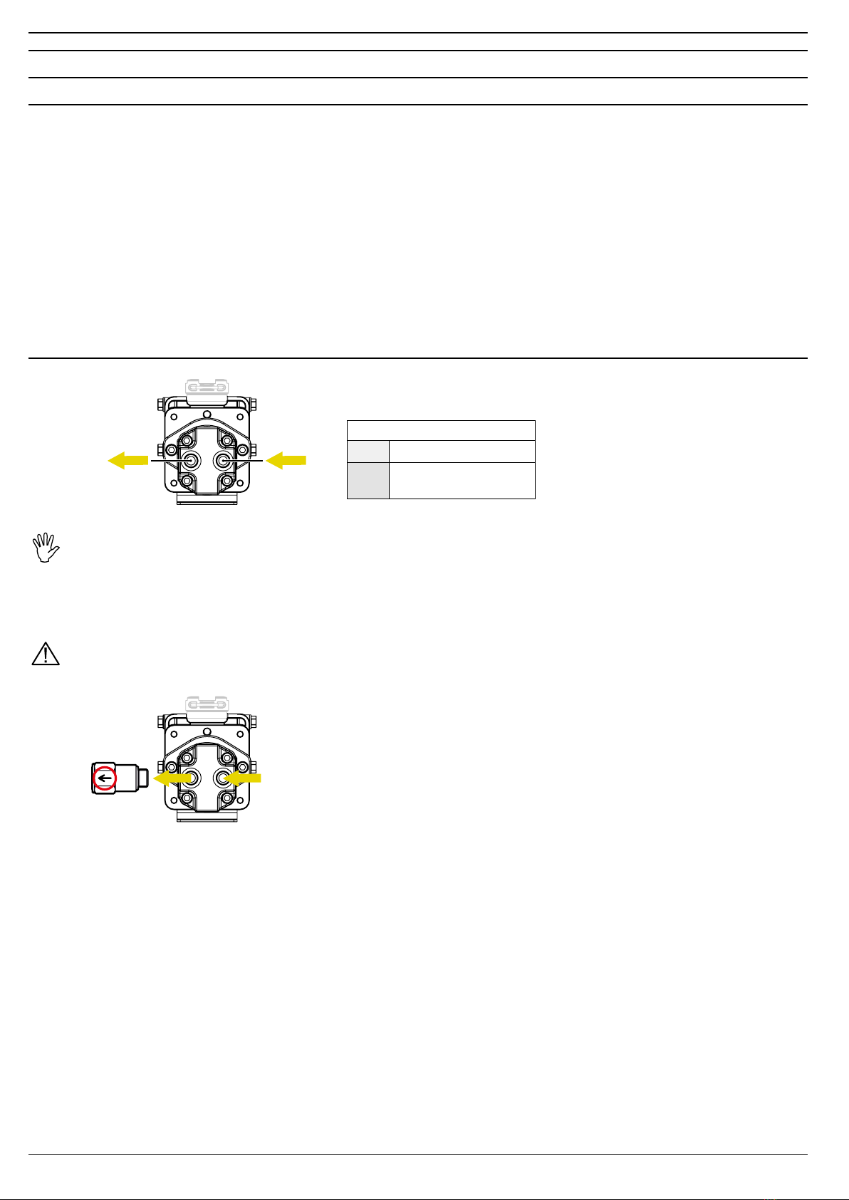
6 Connections ............................................................................................................................................................................................ 8
6.1 Hydraulic motor (OIL) connections ................................................................................................................................................. 8
6.1.1 Safety guidelines............................................................................................................................................................................ 8
6.1.2 Hydraulic motor oil line connection ................................................................................................................................................ 8
6.2 Water connection............................................................................................................................................................................ 9
6.2.1 Safety guidelines ............................................................................................................................................................................ 9
6.2.2 Water/air bleed ............................................................................................................................................................................... 9
7 Starting the pump ................................................................................................................................................................................. 10
8 Maintenance / Diagnostics / Repairs................................................................................................................................................... 10
8.1 Troubleshooting ............................................................................................................................................................................ 10
8.2 Technical data............................................................................................................................................................................... 10
9 End-of-life disposal............................................................................................................................................................................... 10
10 Guarantee terms.....................................................................................................................................................................................11
This manual is an integral part of the equipment to which it refers and must accompany the equipment in case of sale
or change of ownership. Keep it for any future reference; ARAG reserves the right to modify product specications and
instructions at any moment and without notice.

3
1 PRODUCT DESCRIPTION
The series MP400 ARAG pumps are multistage centrifugal pumps designed to work on agricultural machinery for spraying and crop spraying.
Thanks to their exibility they can be positioned on different points of the agricultural machinery and can be used on many different systems.
2 INTENDED USE
CAUTION!
This device is designed to be used ONLY ON AGRICULTURAL MACHINERY FOR SPRAYING AND CROP SPRAYING.
It is FORBIDDEN to use the device for other purposes as this may cause serious accidents.
ARAG can not be held responsible for damages to the equipment, persons, animals or properties caused by the non-observance
of these rules.
CAUTION:
THOROUGHLY FOLLOW ALL SAFETY GUIDELINES DESCRIBED IN THE
FOLLOWING CHAPTERS.
DO NOT START THE PUMP BEFORE READING CHAPTER 7 'STARTING THE PUMP'.
3 PACKAGE CONTENT
The table below indicates the components that you will nd in the MP400 PUMP package:
Legend:
1MP400 Pump
2Instruction manual (CD-ROM)
4 VERSIONS, CODES AND OPERATING CURVES
4.1 Versions and codes
Coupling
Fork Thread
(BSP)
Thread
(NPT) Clamp Motor
Max. water flowrate Max. water pressure Max. oil flowrate Max. oil pressure
CODE CODE CODE CODE l/min GPM bar PSI l/min GPM bar PSI cm3/rev.
970 05021 970 05022 970 05023 970 05024 517 137 7. 5 109 26.5 7 135 1955 7. 2
970 05001 970 05002 970 05003 970 05004 560 148 10.6 154 49.2 13 120 1735 11. 2
970 05031 970 05032 970 05033 970 05034 567 150 11. 0 160 64.3 17 106 1537 14.5
Features of the couplings and pipelines to use: Tab. 5 + 6
Fig. 1
Tab. 1
CONTINUES

4
4.2 Operating curves
4.2.1 How to read the diagrams:
The following diagrams show 2 curves, one continuous and one with a dotted line.
The continuous line shows the water owrate at a specic operating pressure. The dotted line shows the motor oil pressure.
Example: Diagram of a pump (Code 9700502x) with a motor of 7,2 cm3:
To obtain a water owrate equal to 340 l/min with a pressure of 5 bar (1), the pump will have to be powered by an oil circuit that can guarantee a
owrate of 26,5 l/min with a pressure of about 128 bar (2).
4.2.2 Curves

5
Curves (follows)

6
5 INSTALLATION
5.1 Example of a typical system composition
MF
RP
I
A
4
in
out
3
2
1
Legend:
AAgitator MPressure gauge 1suction
FFlowmeter PProportional valve 2bleed line
IFilter RControl valve 3main delivery
4agitation delivery
CAUTION: The pump must always be tted under the liquid level, with a suction line as short and direct as possible and with a
size of AT LEAST the nominal diameter of the inlet.
5.2 Dimensions (mm)
82 Y
147
X X1
364
106
444
358
98
438
358
98
438
352
98
432
Coupling
Fork Thread
(BSP)
Thread
(NPT) Clamp
X(mm)
Y(mm)
W(mm)
Fig. 2
Tab. 2
Fig. 3
111
Motor
X1 (mm)
7, 2
cm³/rev.
116
11,2
cm³/rev.
121
14,5
cm³/rev.
Tab. 3a Tab. 3b

7
5.3 Attachment
The MP400 series pumps are equipped with an attachment with a drilled plate that allows the positioning also in very narrow areas or where there is
just the space for the pump. Use M8 screws and bolts for the xing.
IMPORTANT:
IN ORDER TO INSTALL THE PUMP CORRECTLY, OBSERVE THE FOLLOWING PRECAUTIONS:
1) The inlets/outlets must be placed in xed positions.
2) Before drilling and xing the plate, check the actual space according to the different types of motors or pulleys.
3) Take into account the spaces needed for the correct positioning of the hydraulic pipes, where provided, or the power cables.
4) Choose a well ventilated point for the positioning, as the pump will become hot while in operation.
47.580
120175X1
60
111
Motor
X1 (mm)
7, 2
cm³/rev.
116
11,2
cm³/rev.
121
14,5
cm³/rev.
5.4 Pump assembly direction
The MP400 pump can be tted in different positions, but the outlet must never be pointed downwards (Fig. 5).
OK OK OK NO!
Fi g . 4
Tab. 4
Fig. 5

8
6 CONNECTIONS
6.1 Hydraulic motor (OIL) connections
6.1.1 Safety guidelines
- Use tubes that are suitable to the motor owrate and pressure (ref. Tab. 1).
- Fix the hydraulic tubes checking that after their use under pressure there are no blow-by or oil leakages from the circuit.
- Do not install the pump where it can be subject to severe impacts, or where there is too much heat or in any other point that
can cause the machine to malfunction.
-During the insertion in an existing system, follow all the safety guidelines indicated by the system manufacturer.
-Qualied staff must carry out any type of intervention that requires the modication of the original hydraulic connection
conguration.
ARAG is not liable for damages to equipment, persons, animals or property caused by wrong or unsuitable pump connections.
Furthermore, ARAG can not be held responsible for direct or indirect damages to equipment, machinery, persons or animals
caused by the use of pipes, cable clamps, ties, or any other connection or by the use of unsuitable and improper accessories.
Damages to the pump or to the circuits/objects connected to it, due to the above-mentioned causes, automatically voids the
warranty.
6.1.2 Hydraulic motor oil line connection
in
out
IMPORTANT:
TO AVOID THE BREAKAGE OF THE MOTOR, PAY ATTENTION NOT TO INVERT THE OIL TUBES CONNECTION.
For this purpose, it is recommended to install a check valve.
ARAG check valve (Code 970001 - Ref. ARAG Catalog), to be purchased separately, must be installed in the oil output branch
(out) PAYING ATTENTION TO THE REFERENCE OF THE FLOW DIRECTION, as indicated on the valve body (Fig. 7).
Use the gaskets provided and a tightening torque of 20 Nm.
ARAG is not liable for damages to the system, persons, animals or property caused by the use of a check valve different from the
one indicated. The warranty is to be considered automatically void in case of damages to the pump caused by failure to observe
the above-mentioned instructions.
- The maximum value of the back pressure on the outlet is 3 bar.
- The oil outlet line (drain) should be directed into the oil tank.
- The pipelines must have a nominal diameter not lower than the diameter of the ttings on the motor and they must be perfectly
sealed.
- To avoid loss of pressure, the pipelines should be as short as possible reducing to a minimum the number of hydraulic
resistances (elbows, bottle necks, quick-couplings).
- It is advisable to place a section of exible tube in between the pipelines, this is to reduce the transmission of vibrations.
- All the return pipelines must end below the minimum oil level, this is to avoid the formation of foam.
- Before connecting the pipelines, remove all closing plugs, if any, and make sure they are perfectly clean.
oil
inlet
oil
outlet
Oil tubes diameter
in 1/2"
out 1/2" - max length 10 m or
3/4" - no length limit
Fig. 6 Tab. 5
Fig. 7

9
6.2 Water connection
6.2.1 Safety guidelines
- The pump must always be installed below the liquid level.
- The suction line must be as short and direct as possible.
- Avoid elbows and the enlargement of the diameter in the pipeline to avoid air stagnation.
- The size of the suction and delivery lines must be AT LEAST equal to the nominal diameter of the size of the relevant opening.
- The suction line must be free from air leaks.
- Avoid, if possible, elbows and narrowing in the pipeline on the delivery line, this is to limit possible loss of pressure.
OUT
IN
Inlet/outlet coupling
Fork Thread
(BSP /NPT)
Clamp
T7F
T6F
2"
1 1/2"
2" Full Port
2" Std. Port
Pipelines minimum diameter
50 mm / 2"
38 mm / 1 1/2"
suction (IN)
delivery (OUT)
Couplings diameter and recommended pipelines
6.2.2 Water/air bleed
- Install a breather pipe (Item 2 Fig. 2) in one of the delivery retaining plugs placed on the pump.
The tube diameter must be 6 mm or 1/4".
- Choose the plug located in the highest point according to the installation position of the pump (Fig. 9) in order to eliminate any
air trapped in the pump and to allow a minimum motion of the liquid also when the control unit connected to the pump is not
spraying.
Fig. 8
Tab. 6
Fig. 9
CONTINUES

10
7 STARTING THE PUMP
IMPORTANT: DO NOT RUN DRY THE PUMP (WITHOUT LIQUID).
• Do not use the pump with pressure values above those indicated in the technical specications.
• Do not pump explosive or inammable liquids such as gasoline, kerosene, fuel oil etc. Do not use in explosive atmospheres.
• The pump must be used only with liquids compatible with the materials of its components.
• Do not aim water jets at the equipment.
• Do not use solvents or fuel to clean the case outer surface.
• Only use ARAG genuine spare parts and accessories.
ARAG is not liable for serious personal injuries, damages to the system, to persons, animals or property caused by the non-
observance of the above-mentioned rules, that will automatically void the warranty.
8 MAINTENANCE / DIAGNOSTICS / REPAIRS
8.1 Troubleshooting
CAUSE MALFUNCTION REMEDY
Insufficient owrate (H20)
Hydraulic motor not suitable for the system • Refer to the data/diagrams table.
Loss of air in the suction line • Check and seal tubes and ttings.
Suction line below standard size or collapsed tube • Replace tube (ref. 'connection' section).
Clogged lters • Carry out an adequate maintenance (lter cartridge cleaning).
Rotors clogged • Contact a Service Center to have the rotors checked and cleaned.
Rotor seizure (dry running) • Contact a Service Center to have the rotors replaced.
Hydraulic system (OIL)
overheating
Hydraulic motor not suitable for the system • Refer to the data/diagrams table.
Motor hydraulic tube insufficient size • Check the size of the tubes (Table 4).
8.2 Technical data
Description MP400 Pump
Operating temperature 0 °C ÷ 60 °C
32 °F ÷ 140 °F
Storage temperature -30 °C ÷ 80 °C
-22 °F ÷ 176 °F
Size ref. Par. 5.2
Weight 9,8 kg
9 END-OF-LIFE DISPOSAL
Dispose of the system in compliance with the established legislation in the country of use.
Tab. 7

11
10 GUARANTEE TERMS
1. ARAG s.r.l. guarantees this apparatus for a period of 360 days (1 year) from the date of sale to the client user (date of the goods delivery note).
The components of the apparatus, that in the unappealable opinion of ARAG are faulty due to an original defect in the material or production
process, will be repaired or replaced free of charge at the nearest Assistance Center operating at the moment the request for intervention is made.
The following costs are excluded:
- disassembly and reassembly of the apparatus from the original system;
- transport of the apparatus to the Assistance Center.
2. The following are not covered by the guarantee:
- damage caused by transport (scratches, dents and similar);
- damage due to incorrect installation or to faults originating from insufficient or inadequate characteristics of the electrical system, or to alterations
resulting from environmental, climatic or other conditions;
- damage due to the use of unsuitable chemical products, for spraying, watering, weedkilling or any other crop treatment, that may damage the
apparatus;
- malfunctioning caused by negligence, mishandling, lack of know how, repairs or modications carried out by unauthorized personnel;
- incorrect installation and regulation;
- damage or malfunction caused by the lack of ordinary maintenance, such as cleaning of lters, nozzles, etc.;
- anything that can be considered to be normal wear and tear.
3. Repairing the apparatus will be carried out within time limits compatible with the organizational needs of the Assistance Center.
No guarantee conditions will be recognized for those units or components that have not been previously washed and cleaned to remove residue of
the products used;
4. Repairs carried out under guarantee are guaranteed for one year (360 days) from the replacement or repair date.
5. ARAG will not recognize any further expressed or intended guarantees, apart from those listed here.
No representative or retailer is authorized to take on any other responsibility relative to ARAG products.
The period of the guarantees recognized by law, including the commercial guarantees and allowances for special purposes are limited, in length of
time, to the validities given here.
In no case will ARAG recognize loss of prots, either direct, indirect, special or subsequent to any damage.
6. The parts replaced under guarantee remain the property of ARAG.
7. All safety information present in the sales documents regarding limits in use, performance and product characteristics must be transferred to the
end user as a responsibility of the purchaser.
8. Any controversy must be presented to the Reggio Emilia Law Court.

Conformity Declaration
ARAG s.r.l.
Via Palladio, 5/A
42048 Rubiera (RE) - Italy
P.IVA 01801480359
Dichiara
che il prodotto
descrizione: Pompa centrifuga
modello: MP400
serie: 97005xxx
risponde ai requisiti di conformità contemplati nella seguente Direttiva Europea:
2006/42/CE e successive modificazioni
Applicata nei seguenti requisiti essenziali:
1.1.1, 1.1.2, 1.1.3, 1.3.1, 1.3.4, 1.5.5, 1.6.5, 1.7.4, 1.7.4.1, 1.7.4.2.;
e che la documentazione tecnica pertinente è stata compilata in conformità dell’allegato VII B
di tale direttiva e alle disposizioni nazionali di attuazione della Direttiva Macchine.
Si precisa inoltre che:
• la documentazione tecnica pertinente è custodita da ARAG, nella persona del suo legale
rappresentante, sig. Giovanni Montorsi;
• ci si impegna a trasmettere, in risposta ad una richiesta adeguatamente motivata delle
Autorità Nazionali, informazioni pertinenti sulle quasi-macchine. Tale impegno comprende
le modalità di trasmissione e lascia impregiudicati i diritti di proprietà intellettuale del
fabbricante della quasi-macchina;
• la presente quasi-macchina non deve essere messa in servizio finché la macchina finale
in cui deve essere incorporata non sia stata dichiarata conforme alle prescrizioni di cui alla
Direttiva Macchine 2006/42/CE.
Rubiera, 16 Marzo 2015
Giovanni Montorsi
(Presidente)

D20333_GB-m02 02/2016
42048 RUBIERA (Reggio Emilia) - ITALY
Via Palladio, 5/A
Tel. +39 0522 622011
Fax +39 0522 628944
www.aragnet.com
info@aragnet.com
Only use genuine ARAG accessories or spare parts to make sure manufacturer guaranteed safety conditions are maintained
in time.Always refer to ARAG spare parts catalog.
This manual suits for next models
1
Table of contents
Other ARAG Water Pump manuals
Popular Water Pump manuals by other brands

Simplex
Simplex P140D operating instructions

Graco
Graco E-Flo SP D200S INSTALLATION AND PARTS MANUAL

BRINKMANN PUMPS
BRINKMANN PUMPS SFL650S operating instructions

Pacific hydrostar
Pacific hydrostar 95977 Assebly and operation instructions

Liberty Pumps
Liberty Pumps Pro370 Series installation manual

Blue Guard
Blue Guard BG-SPKit-A quick start guide