Arc Euro Trade SC3 Installation instructions

© Arc Euro Trade Ltd, England 2012
- 1 -
A picture story book to help you dismantle and
reassemble your Sieg SC3 Mini-Lathe
Arc Euro Trade Ltd.
10 Archdale Street, Syston, Leicester, LE7 1NA.
Web: www.arceurotrade.co.uk Phone: 0116 269 5693.
SC3 Mini-Lathe
Dismantling and
Reassembly Guide
eurotradearc co uk
UNBEATABLE VALUE ENGINEERING PRODUCTS

© Arc Euro Trade Ltd, England 2012
- 2 -
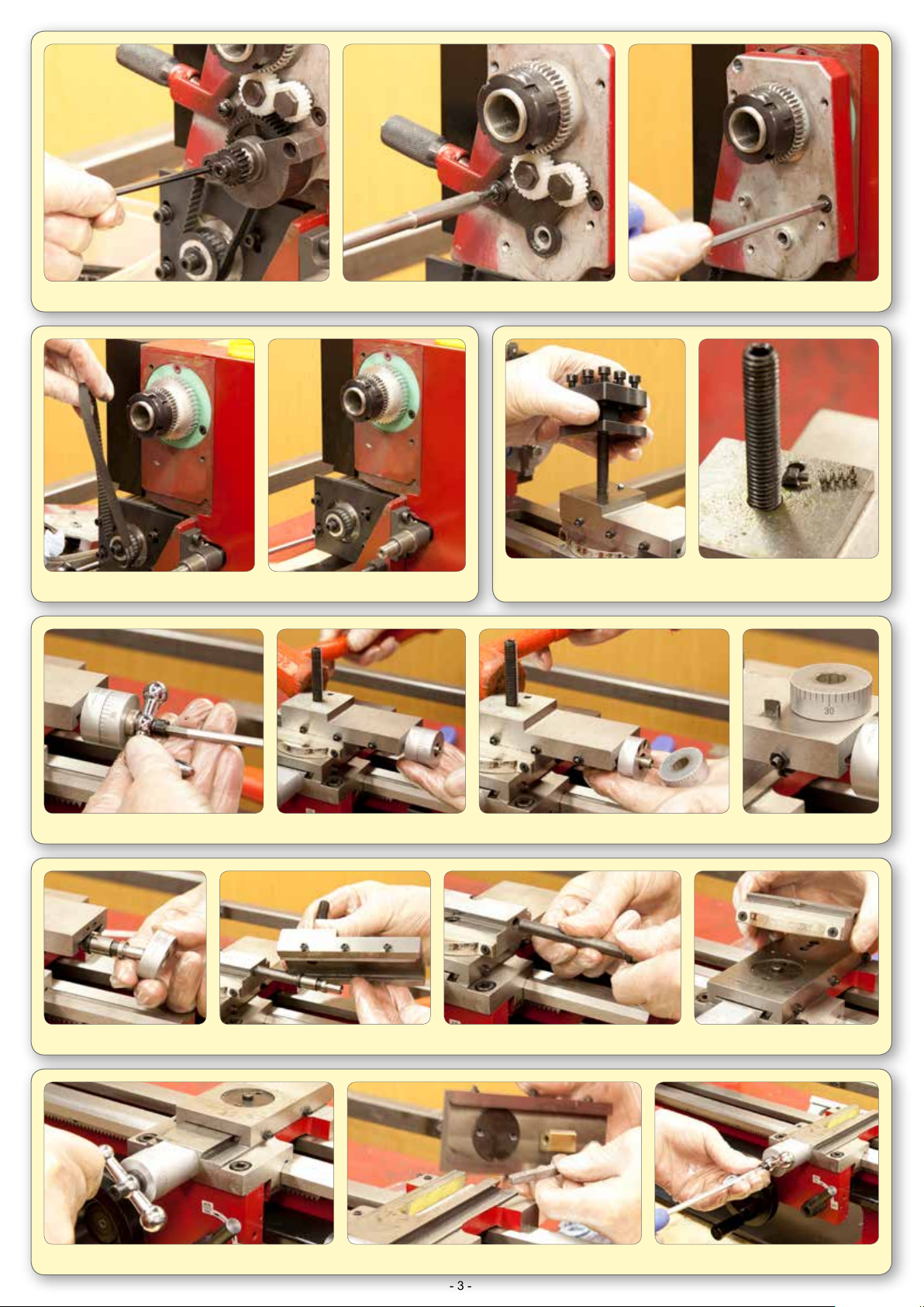
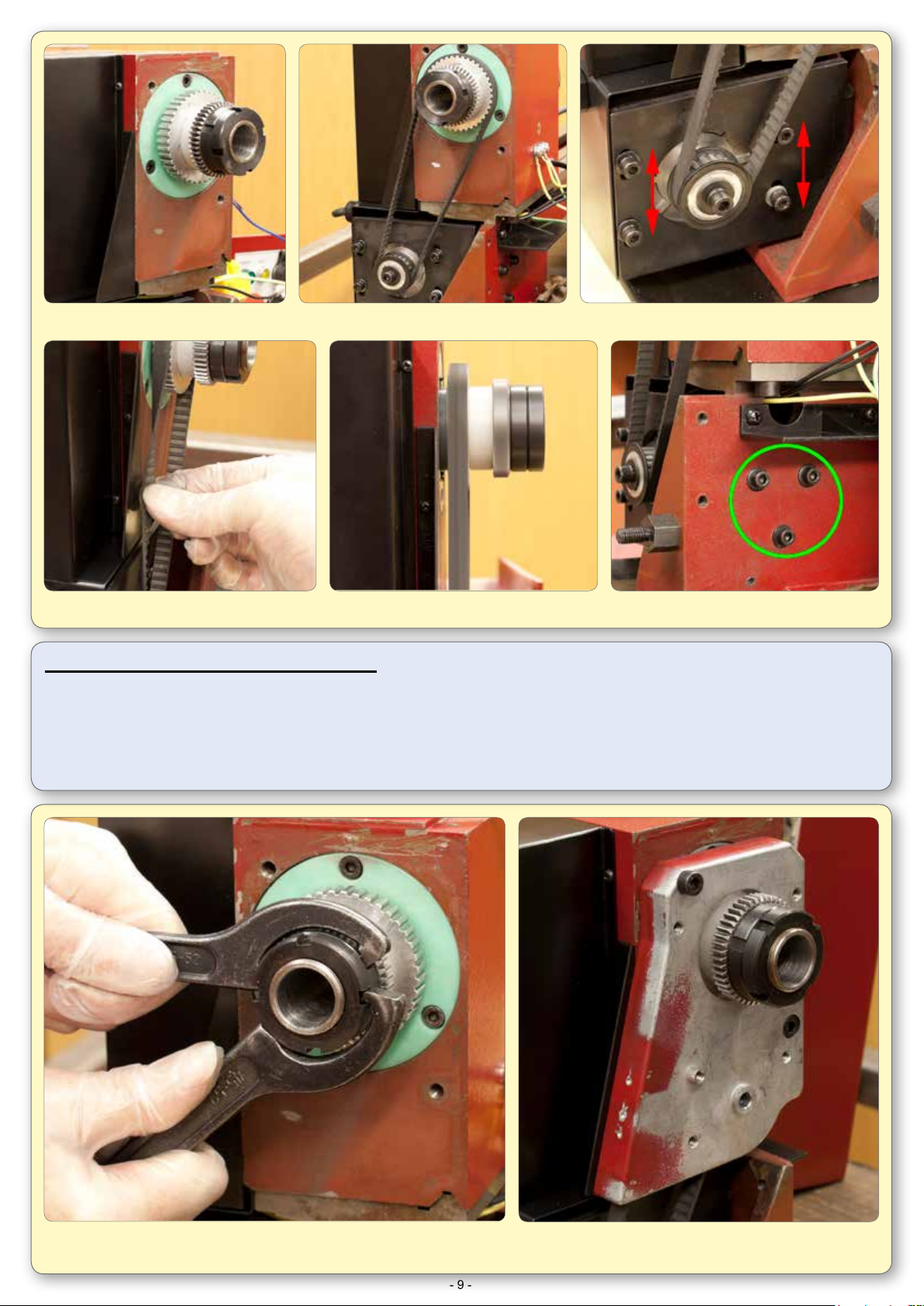
6. Remove the leadscrew gear. 7. Remove the quadrant.
The Sieg C3 Mini Lathe is currently one of the most popular small
lathes available to model engineers today. The new Sieg SC3 takes
the Mini Lathe to a higher level by employing a powerful 500W
brushless motor and eliminating the 2 speed spindle gearbox.
The SC3 has a swing of 180mm (90mm centre height) and is 400mm
between centres. The spindle has a through bore of 20mm and an
MT3 taper whilst the camlock tailstock taper is MT2. The standard
80mm 3 jaw self centring chuck is mounted directly to the spindle
ange which will also accommodate an 80mm 4 jaw independent
chuck, an ER25 collet chuck or an ER32 collet chuck directly on it’s
ø55mm register. A larger 100mm chuck may be tted using one of
our C3 (adaptor) backplates, but we do not recommend the use of a
chuck larger than 100mm.
As mentioned earlier, power is provided by a 500w brushless DC
motor which drives the spindle directly via a toothed timing belt and
is electronically controlled to give a speed range of 100-2500 rpm.
The Sieg SC3 is available in both metric and imperial options and
Standard indexable dials are tted as standard to the cross slide and
top slide. The machine is tted with a socket for an optional spindle
speed display and digital readouts are also an extra option.
This picture story guide is designed to help you dismantle,
reassemble, lubricate and make the proper adjustments to your
lathe.
Before dismantling your SC3 mini lathe, you should read through the
entire guide and assess that you have the required equipment and
skills to complete the task. For instance, some operations require the
use of a lathe and you can’t use your lathe if its all in bits!
Although not expressly stated at each stage in this guide, every part
is thoroughly cleaned in a paran type solvent before reassembly.
For lubrication, we recommend Molyslip HSB grease (ARC code:
170-100-10300), and a good quality lubricating oil such as Rock
Oil HLP 32 Hydraulic Oil (ARC code: 170-150-00400). We do not
recommend using automotive engine oil or 3-in-1 oil.
Please note that Sieg also manufacture the C2, C2A, SC2 and C3
mini lathes which are all smaller variations of the SC3 and will have
some construction dierences. There are also other factories in
China making mini lathes similar to the C3 so these will be dierent
again.
[Updated: 4/12/2017]
1. The lathe out of the box and we are ready to start work. 2. Remove the chuck guard.
3. Remove the end cover. 4. Remove the rear splash guard..
5. Remove the tailstock.
PLEASE READ THIS FIRST

© Arc Euro Trade Ltd, England 2012
- 3 -
12. Remove the tool post.
13. Remove the detent plunger & spring from the compound slide.
11. Remove the drive belt.
14. Remove the ball handle and spacer. 15. Tap the compound slide to remove the micrometer dial taking care not to lose the friction spring.
8. Remove the transfer gear bracket. 9. Remove the tumbler reverse lever assembly. 10. Remove the belt cover.
16. Remove the dial bracket. 17. Remove the compound slide & gib. 18. Remove the feed screw. 19. Remove the slide base.
20. Wind the cross slide o the feed screw. 21. Remove the cross slide & gib. 22. Remove the ball handle & washer.

© Arc Euro Trade Ltd, England 2012
- 4 -
31. Remove the screws holding the rack. 32. Remove the rack from the front of the bed. 33. Remove the chuck from the spindle ange.
26. Remove left hand and right hand leadscrew carrier brackets. 27. Slide out leadscrew.
23. Remove the micrometer dial & friction spring. 24. Remove the dial bracket. 25. Remove the cross slide feed screw.
28. Undo the screws retaining the leadscrew cover... ... and slide out the cover.
29. Undo two screws to remove the apron from the saddle. 30. Slide the saddle o the end of the bed.

© Arc Euro Trade Ltd, England 2012
- 5 -
34. Remove the power board cover. 35. Disconnect the mains leads.
36. Remove 4 screws retaining the control panel and lay it down beside the machine. 37. Disconnect the earth leads.
38. Disconnect power cables and guard
switch wires.
39. Remove the motor cover and pull power cables through from front of machine.
40. Remove motor end cover and mains cable 41. Remove the power board
Dismantling the spindle
Steps 34 to 77 include a bearing change from standard ball raced bearings to taper roller bearings. Switching to taper roller bearings will improve the machining
accuracies and nish.
Since in many cases, taper roller bearings are not an essential upgrade, and because you will need access to another lathe, a hydraulic press and
bearing separator you may wish to keep the standard ball races and skip forward to step 77.

© Arc Euro Trade Ltd, England 2012
- 6 -
48. Press out the spindle assembly. 49. Press out the rear bearing. 50. Spindle assembly removed.
42. Remove the leadscrew guard. 43. Remove the 2 hex socket and 2 hex head screws securing the head to the lathe bed.
46. Remove lock nuts, gear, belt pulley,
2 spacers and the key from the
spindle rear.
45. Remove the front bearing
cover screws.
44. The head may now be lifted clear
of the bed.
47. Remove the rear bearing
cover.
51. Press or pull o bearing and remove bearing
cover from spindle. Note the bearing t.
If the bearings are tight to remove, polish the
spindle journals. The front bearing can be a press t on the shaft but the rear bearing needs
to be push t to allow accurate preload adjustments to be made by the two C-nuts.
52. Polish the spindle and test the t by using
one of the old bearings (if not damaged).
53. Fit bearing cover and press on
nose bearing.
54. Press front and rear outer bearing races into the head.

© Arc Euro Trade Ltd, England 2012
- 7 -
55. Re-t the head and lock down. 56. Re-t the leadscrew cover.
57. Grease the front race and rollers and assemble. 58. Fit the front bearing cover. 59. Grease the rear race and rollers and t.
60. Fit the rear bearing cover. 61. Fit the key and plastic spacer. 62. Fit the spindle drive belt pulley.
63. Check alignment of drive pulleys and adjust
spacer behind spindle pulley if necessary.
64. Fit the outer spacer and gear.
65. Fit the spindle C nuts, adjust out bearing
backlash with minimum preload and only
nip up the C nuts for the time being.

© Arc Euro Trade Ltd, England 2012
- 8 -
66. Fit the power board 67. Thread wires from bottom of motor board through motor cover and then through bed to front.
68. Fit motor cover. 69. Connect Mains In to top of board. 70. Fit power board cover.
71. Reconnect the earth wires to the head.
74. Check the gear alignment. 75. Adjust this spacer to correctly align the two gears.
72. Fit the power wires to the emergency stop switch (noting correct
orientation) and t the guard switch wires.
73. Temporarily t the belt cover and tumbler
reverse lever assembly.

© Arc Euro Trade Ltd, England 2012
- 9 -
Running the spindle for the rst time:
1. Follow the Start-Up procedure with the motor running forwards.
2. Run the machine at a low RPM. The machine should run smoothly with minimal noise and
vibration. If not turn o the machine and investigate the cause of the problem.
3. Increase the speed and run for 10 minutes at a higher RPM.
80. Run the spindle following the procedure below and check the belt is centred on the pulley. If not
the motor angle may be adjusted by slackening these screws. Check the belt tension again.
76. Remove the tumbler reverse
assembly and belt cover again.
77. Fit the drive belt and adjust the belt tension. 78. Belt tension adjustment screws.
79. When adjusting belt tension, it should
twist easily through 90°
81. After running the spindle to warm it up and settle the grease, check and adjust
the preload again. Lock the C nuts when the preload appears to be OK. Take
care not to overdo the preload as this could overheat and damage the bearings.
82. Re-t the belt cover.

© Arc Euro Trade Ltd, England 2012
- 10 -
88. Place the saddle on the bed and
check to see how it sits.
89. If it rocks, blue the bed and slide
the saddle up and down to nd the high
spots.
90. Scrape, le or stone down the high
spots until the saddle sits at on the bed.
91. Loosen shear plate adjusting screws below the level of the plate and loosely t to saddle. 92. Oil bed and saddle and slide saddle onto bed.
86. Drill and tap the xing holes deeper if necessary. 87. Final t rack making sure it seats properly in the corner.
Carry out all the following adjustments to both the
front and rear shear plates step by step.
93. Lightly pinch middle cap screw.
94. Screw in adjusting screws until just touching.
95. Slacken the middle cap screw.
96. Screw in both adjusting screws 1/2 turn.
97. Pinch up middle cap screw.
83. Scrape any paint o the bed shears.
85. If necessary, radius top rear edge of
the rack and trial t again.
84. Trial t the rack to check if it seats well or rocks.
98. Test slide saddle up and down the bed. There
should be slight drag with no free play. Lightly
pinch up remaining cap screws checking after
each one and adjusting as required.

© Arc Euro Trade Ltd, England 2012
- 11 -
104. Loosely t leadscrew bracket & grease bore. 105. Grease end of leadscrew and feed through 1/2 nut and into bracket at headstock end.
106. Grease end of leadscrew and bracket bore and temporarily x in place.
101. The leadscrew brackets as they come on
the machine. Notice there is no means of
lubricating the bearing surfaces other than at
each end of the bracket.
102. Drill oil holes through to the bore using a
centre drill.
103. Finish o by cutting oil grooves in the bore
using a Dremel and a 3mm ball end burr
similar to the one shown in the inset.
(ARC code: 060-030-00310 - Carbide Burr 3mm Ball)
99. Oil and/or grease the gears and shafts, dovetail and half nut of the
apron assembly. Check 1/2 nut dovetail is correctly adjusted by
operating the lever.
100. Temporarily t the apron to the saddle.

© Arc Euro Trade Ltd, England 2012
- 12 -
117. Fit tumbler reverse assembly. 118. Check free play in gears: Forward... ... Neutral... ... and Reverse.
107. Slightly loosen apron xing screws.
116. Oil the tumbler reverse gear shafts.
110. Return saddle close to leadscrew bracket
and lock 1/2 nut. Remove bracket screws.
113. Check the bracket holes align with holes
in bed. If the holes are misaligned, slot the
bracket holes to correct and rex the screws.
108. Lock 1/2 nut onto leadscrew and tighten
apron xing screws.
115. Strip, clean, oil / grease and reassemble the tumbler reverse detent assembly.
111. Check the bracket holes align with the holes
in bed. If holes are misaligned, slot the
bracket holes to correct and rex screws.
114. Return saddle to tailstock end and lock 1/2 nut. Rock
handwheel back and forth with nger over end of leadscrew
to check for end oat. Tap brackets in to remove end oat.
109. Unlock 1/2 nut and rack saddle up and down bed
to check pinion has no tight spots on rack.
112. Move saddle to headstock end and lock 1/2 nut.

© Arc Euro Trade Ltd, England 2012
- 13 -
125. Check for correct gear alignment.
120. Oil the transfer gear shaft. 121. Grease the transfer gear shaft.
126. “Tweak” the lower quadrant bracket until the gears are in proper alignment.
119. The mesh and neutral position can be improved
by adjusting the position of the belt cover.
123. Oil the lower quadrant gear shaft.122. Fit the transfer gear assembly.
124. Temporarily t the gear quadrant.
DO NOT engage the gears.
127. Fit leadscrew gear D. 128. Adjust backlash between gears C and D. 129. Engage quadrant and adjust backlash between gears A and B.
130. Very lightly grease gears.
131. Run spindle to check for noisy gear meshing and
readjust backlash if necessary.
132. Engage 1/2 nut and power the saddle back and
forth along the bed.

© Arc Euro Trade Ltd, England 2012
- 14 -
138. Temporarily t the cross slide feed screw and bracket and
check for backlash.
139. To reduce backlash, machine the rear face of the bracket.
140. To increase backlash, machine a little from the recess. Remove the feed screw and bracket and put to one side.
141. Place cross slide on saddle
and check for clearance in
corners of dovetail.
145. View gib strip to check if
it’s sitting correctly. If OK,
disassemble.
142.
Modify gib screws or replace
with cone point screws.
146. Fit top slide base retaining plate. 147. Drop in gib strip and lubricate all ways.
143. Assemble cross slide and gib strip. 144. Fit adjusting screws lightly.
133. Fit end cover and front panel. 134. Remove right hand leadscrew bracket
and t screw guard.
135. Pinch up the guard screws.
136. Fit the leadscrew bracket with the 1/2 nut locked for position. 137. Wind the carriage up and down the bed to check guard clears
and tighten the screws.

© Arc Euro Trade Ltd, England 2012
- 15 -
148. Assemble onto saddle. 149. Fit adjusting screws and adjust so slide can be moved back and forth easily by hand.
150. Grease / oil the feed screw and bracket. 151. Assemble onto the saddle. 152. Fit the handle.
160. Remove the handle again in order to t the micrometer dial and friction spring. 161. Ret the handle assembly.
153. Slacken the bracket screws, wind the slide right back and tighten the screws.
154. Wind the cross slide in and out. If there is any tightness, the feed screw nut will need adjusting.
155. The centre screw is for adjusting the position
of the nut in an up/down direction and the
two outside screws are for locking. Slacken
all three screws for now.
159. Make nal adjustments to the
gib screws for free movement of
the handle with little drag.
156. Put nger pressure on handle and
screw-in the adjusting screw until
you can feel it just touching the nut
and then +¼ to ½ turn extra.
157. Pinch up the cap screws equally
while winding the slide in and out
until handwheel turns freely and
with minimum drag.
Continue adjusting all three screws
until the slide moves freely along it’s
full travel.
158. If required, slacken and reposition
bracket and return to adjusting the
nut.

© Arc Euro Trade Ltd, England 2012
- 16 -
163. Temporarily t top slide to compound base
and check for clearance in corners of dovetail.
162. Fit compound base to cross slide. 164. Oil top slide assembly and t.
167. Oil / grease feed screw and t. Oil / grease end of feed screw and bracket and t.
168. Turn the feed screw to check it turns freely. 169. Assemble and t the micrometer dial and friction clip to feed screw.
170. Fit the spacer and handle and wind the slide back and forth.
165.
Fit gib strip and adjusting screws making sure they engage in the gib strip dimples.
166. Adjust the screws so the slide will move back and forth easily by hand.
171. Measure backlash with a feeler gauge.

© Arc Euro Trade Ltd, England 2012
- 17 -
The Completed Machine
173. Final adjust the top slide gib to your
preference and lock-o the screws.
174. Grease and t the tool post spring and plunger and t the tool post. 175. Fit the chuck & Guard. 176. Fit the tailstock.
177. Fit the rear guard.
172. Backlash can often be reduced by turning a recess in the spacer to clear the shoulder on the end of
the feed screw. The recess depth should be slightly less than the measurement taken with the feeler
gauge to allow some clearance. Adjust for free movement with minimal backlash.
Table of contents
Popular Lathe manuals by other brands

HOLZMANN MASCHINEN
HOLZMANN MASCHINEN ED1000FB user manual

Optimum
Optimum OPTIturn TM 3310 operating manual

HOLZMANN MASCHINEN
HOLZMANN MASCHINEN ED 300ECO user manual

Promac
Promac PBD-2140V operating instructions

Scheppach
Scheppach Lata 7.0v Translation from the original instruction manual

Delta
Delta LA200 instruction manual

Traub
Traub TNX65 operating instructions

Evenheat
Evenheat Studio Pro 28 Installation and operating instructions

Axminster
Axminster Hobby Series manual

Central Machinery
Central Machinery 33684 Assembly and operating instructions

STRATOS
STRATOS FU-230 Original operating manual

Powermatic
Powermatic 45 Maintenance instructions and parts list