Arc Machines 501 User manual

10500 Orbital Way
Pacoima, California 91331 U.S.A.
MODEL 501 POWER SUPPLY
OPERATION MANUAL
Document No. 740099
Rev. !

!"#$%&'()*$%+&,)-.//00
1&23)4
HEADQUARTERS
Arc Machines, Inc.
10500 Orbital Way
Pacoima, CA 91331 U.S.A.
Tel.: 1- 818 896-9556
Fax: 1-818 890-3724
EUROPEAN OFFICE
Arc Machines, Inc.
Chemin du Lavasson 2
CH-1196 Gland
Switzerland
Tel.: +41 / 22 / 995.00.51
Fax: +41 / 22/ 995.00.59
GERMAN OFFICE
Arc Machines GmbH
Markelsbach 2
D-53804 Much, Germany
Tel.: +49/2245 / 91680
Fax: +49/2245 / 916868
UK OFFICE
Arc Machines UK Limited
10 Ashurst Court, London Road
Wheatley, Oxford OX331ER
England
Tel.: +44/1865/872121
Fax: +44/1865/876909

MODEL 501
POWER SUPPLY
Operation Manual
Arc Machines, Inc.
General Guidelines for Welding with the
AMI Model 501 Hotwire Power Supply
The Arc Machines, Inc. Model 501 Hotwire Power Supply was designed to
supply resistance-heated filler wire at near-melting temperatures to the weld
pool thereby increasing the arc energy available to melt the base metal. The
hot wire process increases the deposition rate and is usually run at higher
welding speeds than cold wire systems. When used with GTA welding sys-
tems, such as Arc Machines’ Model 415 Microprocessor-based power supply,
high-quality weld deposits characteristic of the gas tungsten arc process are
obtained.
The Model 501 uses AC current to preheat the wire. True values of current
and voltage allow welding engineers to precisely calculate energy input in
Joules per inch based on true RMS values.
The hot wire process is normally run in the flat welding position. Out-of-
position welding is possible, but may not provide the desired benefits.
Document Number: 740099
Effective Date: January, 2005

Table of Contents
!"#$%&'()*"3)-.//00
1&23)4
INTRODUCTION
Applications
Hot Wire Application with
AMI Model 415 and M-2
SAFE OPERATION
Safety Precautions
M-501 Do’s and Don’ts
Warnings
MODEL 501
SPECIFICATIONS
POWER SUPPLY
OPERATION & FUNCTIONS
Wire Feeder
System Configurations
WELDING
JOINT PREPARATION FOR
HOT WIRE WELDING
ELECTRICAL DRAWINGS
GRAPHICAL SYMBOLS
INDEX
INDEX
1
2
3
4
5
6
7
8
9
MODEL 501
Hotwire Power
Supply
OPERATION MANUAL
General Guidelines for
Welding with Hot Wire

!"#$%&#'()*+,$-)#.$%/0*1$234$5/67("*$8/7*"$9:;;1<$
=/#:>*)6$?:>@*"$AB33CC$$$$$$$$$$$$$$$$$$$$$$$$$$$$$$$$$$$$$$$D'&;6*"$4.$8&E*$4.
F*G.$H
Chapter 1. Introduction
Filler metal in the form of wire is commonly added to welds in the GTA weld-
ing process, particularly when heavy wall thicknesses are being welded. A
wire feeder is used to deliver the wire to the weld pool and a power supply (or
controller) controls the rate of wire entry. The wire may be either cold (ambi-
ent temperature) or hot. Hot wire is normally fed into the trailing edge of the
pool while cold wire is fed into the leading edge. The hot wire GTAW (TIG)
welding process differs from the cold wire process in that the filler wire is
electrically pre-heated to near melting temperature before entering the weld
pool. This prevents the wire from chilling the weld pool and allows the filler
metal to flow out across the weld puddle resulting in a smooth, attractive
weld bead. Since nearly all of the full energy of the welding arc is available for
penetration, more wire can be deposited and fill rates are significantly higher
than with cold wire. (See graph on page 2.)
The Arc Machines, Inc. Hot Wire Power Supply Model 501 has controls for
(heating wire) voltage. The standard mode of operation for
Hot-wire set-up with GTAW torch and Model 2

!"#$%&#'()*+,$-)#.$%/0*1$234$5/67("*$8/7*"$9:;;1<$
=/#:>*)6$?:>@*"$AB33CC$$$$$$$$$$$$$$$$$$$$$$$$$$$$$$$$$$$$$$$D'&;6*"$4.$8&E*$I.
F*G.$H66
"#e Model 501 is Constant AC Voltage (0 - 10 Volts true$%&'). The M501
implements advanced technology with significant competitive advantages.
AC current is used to minimize magnetic interference (arc$blow). The AC
current of the M501 is far more precise and more sinusoidal than competitive
machines, being very close to a true sine wave. The ability to sense the hot
wire voltage at the tip of the wire feed tube, in addition to sensing the internal
voltage, provides an operational advantage because measuring the voltage at
the work is more accurate and not influenced by irrelevant factors such as cable
length, that can affect the internal reading. The accuracy of true RMS provided
by these measurements make it possible to duplicate production conditions from
one set-up to the next with excellent repeatability of process.
Applications
The Model 501 can be operated by an Arc Machines’, Model 415 Power
Supply, an external weld process controller or program, or can stand alone
and be operated from its own pendant. The hot wire GTAW process produces
a very clean weld with a very low incidence of porosity. The applications for
GTAW hot wire are those that require high-quality welds, but where faster
deposition rates than cold wire GTAW are desired. A conservative estimate of
deposition rates achievable with the M501 would be from 4 to 6 lbs per hour
to a maximum of about 8 lbs per hour. This makes it practical for overlays,
seam welds and other similar type welds in the 1G (downhand) welding
$
$
$
$$$$$$$$$$$$$$$$$$$$$$$$$$$$$$$$$$$$$$$Deposition rates for Gas Tungsten Arc
$$$$$$$$$$$$$$$$$$$$$$$$$$$$$$$$$$$$$$$Welding with Cold and Hot Steel Filler
$$$$$$$$$$$$$$$$$$$$$$$$$$$$$$$$$$$$$$$Wire. 5,"%)(6&)789)8&:;<'=)>?';+""@A)
)))))))))))))))))))))))))))))))))))))))*<'(6)B;3A)2004

!"#$%&#'()*+,$-)#.$%/0*1$234$5/67("*$8/7*"$9:;;1<$
=/#:>*)6$?:>@*"$AB33CC$$$$$$$$$$$$$$$$$$$$$$$$$$$$$$$$$$$$$$$D'&;6*"$4.$8&E*$J.
F*G.$H
position. For example, hot wire GTAW would be suitable for welding high-
quality stainless steel tanks and vessels that are rotated during welding.
While it would be tempting to apply hot wire technology to true out-of-posi-
tion orbital welding, the significant increase in deposition that can be
achieved in downhand hot wire welding will not be seen in orbital applica-
tions. However, some benefit may be achieved in orbital applications at the
expense of greater complexity.
The GTAW process is metallurgically “simple” in
that the electrode is not consumed and filler
metals added to the weld may be precisely
designed to achieve a particular metallurgical
result. Thus, the hot wire GTAW process is
particularly applicable to 300 series stainless
steel as well as to engineered materials such as
duplex stainless steels, or high-nickel alloys,
where the metallurgical properties of the base
metal may be adversely affected by welding
unless high-quality welding procedures are
employed. The proper use of the GTAW process
with the addition of hot wire can optimize the
corrosion resistance and/or mechanical proper-
ties of the weldment and have a beneficial effect
on the material performance in service.
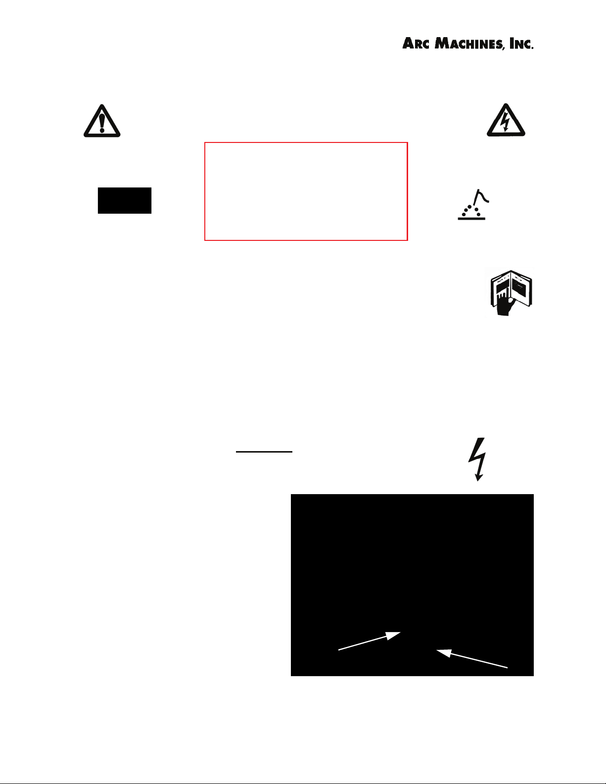
The Model 501 Hot Wire Power Supply can be used in combination with AMI’s Model 2 and
Model 415 Power Supply for fast, high-quality, heavy-duty applications such as turbines. The
photos show a demonstration of cladding at a trade show with the Model 2 with a hot wire
torch. Photo on the right is a close up of the torch.
Arc Machines Model 415 Windows!-
based Power Supply/Controller

!"#$%&#'()*+,$-)#.$%/0*1$234$5/67("*$8/7*"$9:;;1<$
=/#:>*)6$?:>@*"$AB33CC$$$$$$$$$$$$$$$$$$$$$$$$$$$$$$$$$$$$$$$D'&;6*"$4.$8&E*$B.
F*G.$H
Hot Wire application with AMI Model 415 and Model 2
A versatile hot-wire welding automation system may be created by equipping
an Arc Machines’ Model 2 with a Hot-Wire Torch with AVC and oscillation and
optional video vision system and using an Arc Machine’s Model 415, GTAW
400 amp DCSP Power Supply as a controller.
The Model 415 is Windows!-based with built-in digital data acquisition and
multi-servo control capabilities. It is a very capable power supply that is easy
to operate. The heart of its flexibility is the emphasis on user-definability.
Almost all function ranges and modes can be defined by the user to exactly
match the unique Model 2 configuration being used. The closed-loop motor
servos and optional open-loop motor manipulator controls make these sys-
tems ideal for work-cell manufacturing environments.

!"#$%&#'()*+,$-)#.$%/0*1$234$5/67("*$8/7*"$9:;;1<$
=/#:>*)6$?:>@*"$AB33CC$$$$$$$$$$$$$$$$$$$$$$$$$$$$D'&;6*"$I.$8&E*$4.
F*G.$H
Chapter 2. Safe Operating Procedures
Safety Precautions for Model 501 Operation
Arc Welding Precautions
Arc Welding is potentially very hazardous unless safety precautions
are observed. Operators must receive adequate training before
being allowed to operate any type of welding equipment. Read this
manual carefully before operating welding and/or hot wire
equipment. Although the Model 501 hot wire power supply has an open cir-
cuit voltage of only 16 volts and so does not represent an extreme shock haz-
ard by itself, exposed parts operating at very high temperatures represent a
burn hazard. Operators must wear proper protective clothing including eye
protection when operating welding equipment. This chapter of the manual
explains and illustrates common dangers and precautions to take while oper-
ating welding equipment.
THE ELECTRODE SHOULD ALWAYS BE CONSIDERED A
POSSIBLE SHOCK HAZARD and touching it or internal
circuits could prove fatal.
This is especially true whenever the
system is:
• IN SEQUENCE
• READY TO WELD,
• IS WELDING,
• OR HAS JUST FINISHED
WELDING.
When replacing or adjusting the
electrode:
• Set power supply to “TEST”
mode Left arrow shows location of hot wire tube while right
arrow points to the electrode in a GTAW torch.
AVOID ALL CONTACT
WITH THE WELDING
WORK (GROUND) OR
ELECTRODE DURING ARC
START.

!"#$%&#'()*+,$-)#.$%/0*1$234$5/67("*$8/7*"$9:;;1<$
=/#:>*)6$?:>@*"$AB33CC$$$$$$$$$$$$$$$$$$$$$$$$$$$$D'&;6*"$I.$8&E*$I.
F*G.$H
HF Arc Start
Most AMI Power Supplies feature RF (radio frequency) Arc Starting. This is a
High/Voltage/High Frequency electrical transmission process. The GTAW pro-
cess requires electrical potential (high
voltage) to be present on the elec-
trode and on exposed internal termi-
nals during arc starting and during
welding.
ALL AMI Power Supplies contain a
“bleeder” circuit to ground any resid-
ual potential after welding or after an
aborted or bad “arc attempt”. How-
ever, these circuits take a few sec-
onds or could fail.
for Safe Use of Welding/ Hot Wire Equipment
Caution: Only experienced personnel familiar
with the operation and safe practice of welding
equipment should install or use this equipment.
DO’S
1. Do disconnect input power before servicing equipment.
2.Do properly install and ground this equipment.
3. Do VERIFY correct input voltage (200 to 240 VAC @
25 Amps) before plugging in the Model 501.
4. Do turn off equipment when not in use.
5. Do calibrate wire feed each time the Model 501 is
connected.
AMI Model 501 Hotwire Power Supply with cover
removed.
MODEL 501 DO’S AND DON’TS
Model 501 and RP

!"#$%&#'()*+,$-)#.$%/0*1$234$5/67("*$8/7*"$9:;;1<$
=/#:>*)6$?:>@*"$AB33CC$$$$$$$$$$$$$$$$$$$$$$$$$$$$D'&;6*"$I.$8&E*$J.
F*G.$H
6. Do CHECK ALL CABLE AND QUICK-DISCONNECT FITTINGS to
insure proper seating.
7. Do KEEP PROTECTIVE COVERS ON THE MOTOR CABLE
CONNECTORS when not in use.
8. Do wear approved safety glasses with side shields.
9. Do use protective screens or barriers to protect from
flash and glare. The intense light associated with arc
welding can cause damage to the retina of the eye, while
infrared radiation may damage to the cornea and result
in the formation of cataracts.
Invisible ultraviolet light (UV) from the arc can cause
"arc eye" or "welder's flash" after even a brief
exposure (less than one minute). The symptoms of arc
eye usually occur many hours after exposure to UV light,
and include a feeling of sand or grit in the eye,
blurred vision, intense pain, tearing, burning, and
headache.
The arc can reflect off surrounding materials and burn
co-workers who work nearby. About half of welder's flash
injuries occur in co-workers who are not welding. Welders
and cutters who continually work around ultra violet
radiation without proper protection can suffer permanent
eye damage.
10. Do wear welding goggles or suitable eye protection
when working around a welding arc.
Exposure to ultraviolet light can also cause skin burns
similar to sunburn, and increase the welder's risk of skin
cancer.
11. Do wear gloves and protective clothing to prevent
burns from hot surfaces and from UV exposure.
12. Do keep your head out of welding fumes. Do not
breathe fumes.
13. Do use a respirator if ventilation is not good.
14. Do read Material Safety Data Sheets (MSDS) and the
manufacturer’s instructions for metals, consumables,
solvents etc.

!"#$%&#'()*+,$-)#.$%/0*1$234$5/67("*$8/7*"$9:;;1<$
=/#:>*)6$?:>@*"$AB33CC$$$$$$$$$$$$$$$$$$$$$$$$$$$$D'&;6*"$I.$8&E*$B.
F*G.$H
15. Do protect gas cylinders and secure them firmly them in
upright position. A damaged cylinder can explode and fly
through the air like a guided missile.
16. Do USE PIPE STANDS, CLAMPS, ALIGNMENT TOOLS,
etc. to hold weld components in position for welding.
Tack welding of components with a manual torch prior to
welding may be necessary in some applications.
MODEL 501 DON’TS
1. Don’t watch the arc. The light can cause blindness.
2. Don’t attempt to weld without a secure BARE METAL WORK
(GROUND) CONNECTION when using the Model 501.
3. Don’t attempt to weld without PROPER FACING AND
CLEANING OF THE MATERIAL to be welded.
4. Don’t route the cables where they will be SUBJECT TO
DAMAGE from traffic or equipment.
5. Don’t C$:: on cables. This will result in DAMAGE TO THE
EQUIPMENT.
6. Don’t add oil or grease to the wire feed mechanism.
7. Don’t increase GAS FLOW RATE (CFH) to GTAW torch
beyond levels that could result in arc instability.
8. Don’t switch the Model 501 Power Supply ON and OFF
rapidly with circuit breaker (CB-1).
RF and EMI Emissions
Arc Machines’ policy is to comply with the IEC and FCC
regulation. Every effort has been made to reduce RF emissions
from our power supplies to the absolute minimum. (See Model
415 Operation Manual P/N 740095 for more information.)

!"#$%&#'()*+,$-)#.$%/0*1$234$5/67("*$8/7*"$9:;;1<$
=/#:>*)6$?:>@*"$AB33CC$$$$$$$$$$$$$$$$$$$$$$$$$$$$$$$$$$$$$$$D'&;6*"$I.$8&E*$2.
F*G.$H
Model 501 Hot Wire Power Supply
W71*D*E9F
WARNING:Touching energized electrical parts can cause fatal
shocks and burns. When in weld sequence the electrode and work
are electrically energized. Incorrectly installed or improperly
grounded equipment is a hazard.
WARNING:This equipment is authorized to use a type of arc starter
that produces a High Frequency Radio Wave (sometimes called
HF and/or RF Starting). It can cause interference and sometimes
even damage to nearby electronic equipment (such as computers)
that are unprotected or poorly protected against such interference.
WARNING:Magnetic fields from High Currents can affect pace-
makers. PACEMAKER WEARERS KEEP AWAY UNTIL CONSULTING YOUR
DOCTOR.
WARNING:Disconnect the input power to the machine before
opening or servicing. Discharge all circuits that store high voltage
such as capacitor packs. Only QUALIFIED service personnel should
open this equipment.
Safety Precautions
This section, concerning safe operating procedures for the
Model 501 Hot Wire Power Supply, should be read and under-
stood before proceeding to other sections of the training man-
ual. It also contains precautions an warnings for the operation of
welding equipment in general. In addition, users should refer-
ence and become familiar with “ANSI-49.1 Safety in Welding and
Cutting” published by the American National Standards Institute.

!"#$%&#'()*+,$-)#.$%/0*1$234$5/67("*$8/7*"$9:;;1<$
=/#:>*)6$?:>@*"$AB33CC$$$$$$$$$$$$$$$$$$$$$$$$$$$$$$$$$$$$$$$D'&;6*"$I.$8&E*$K.
F*G.$H
MODEL 501 WARNINGS Continued:
WARNING:Welding can cause fires or explosions. Do not weld near
flammable or explosive materials. Watch for fire. Have proper type
of extinguisher in work area.
WARNING: Welding Operators should wear non-flammable
protective clothing, footwear and head gear.
WARNING: Never weld on sealed containers or pipes. This may
result in an EXPLOSION.
WARNING: Welding produces high temperatures in both the
welded components and the welding equipment. Both can cause
severe burns. Do not touch recently welded components. Avoid
touching internal components of the welding system soon after use.
Avoid touching torch components and welding fixtures soon after
welding.
WARNING: The welding arc emits ultra-violet (UV) radiation and the
molten weld gives off infra-red. Both can burn eyes and skin if
unprotected. Suitable eye and skin protection must be worn.
WARNING: Weld materials can emit toxic fumes during welding.
HEXAVALENT CHROMIUM, which is given off when stainless steel is
welded, causes lung cancer in humans. See Semi F79-0703
Appendix- HEXAVALENT CHROMIUM ALERT. WELD ONLY IN
AREAS WITH ADEQUATE VENTILATION.

!"#$%&#'()*+,$-)#.$%/0*1$234$5/67("*$8/7*"$9:;;1<$
=/#:>*)6$?:>@*"$AB33CC$$$$$$$$$$$$$$$$$$$$$$$$$$$$$$$$$$$$$$$D'&;6*"$I.$8&E*$A.
F*G.$H
MODEL 501 WARNINGS Continued:
WARNING: Most GTAW gases like argon are non-toxic, however,
argon is heavier than air and will displace the normal atmosphere in
enclosed areas. DO NOT WELD IN ENCLOSED AREAS WITH-
OUT PROPER VENTILATION OR RESPIRATORS.
WARNING: AMI factory training is essential for all Welding Opera-
tors and Maintenance Technicians who operate AMI equipment.
Consult factory for dates of training classes and other training
information.
WARNING: Some systems, such as the M-501 Power Supply are
intended solely for indoor use and must be kept dry. Before operat-
ing, storing, or handling, always make sure that the M-501, M-501-
Operator Pendant, weld heads and cables are not exposed to rain
or standing water. SYSTEM COMPONENTS ARE NOT WATER
PROOF.
WARNING: Keep hands and fingers clear from moving parts such
as fans, gears, rotors, and Rotation Mechanisms.
The wire for the M-501 feeds at a high rate of speed and as it
enters the puddle is at near melting temperature. Take care to avoid
contact with the wire. Keep eyes protected.

!"#$%&#'()*+,$-)#.$%/0*1$234$5/67("*$8/7*"$9:;;1<$
=/#:>*)6$?:>@*"$AB33CC$$$$$$$$$$$$$$$$$$$$$$$$$$$$$$$$$$$$$$$D'&;6*"$J.$8&E*$4.
F*G.$H
Chapter 3. Specifications for the Model 501 Power
Supply
AMI Model 501
True RMS Hotwire Precision Power Supply
Features
"Calibrated Precision Closed Loop Servo Output Control
"Constant Voltage (CV) True RMS mode-of-operation
"Constant Current (CC) True RMS mode-of-operation
"Voltage Feedback Sensing at the wire feed tip or internal to
the power supply
"True RMS instrumentation Outputs (Amps and Volts)
"Optional Manual Remote Programming Pendant
"Control input for connection to an external
controller/programmer
Basic Specifications
Input: 200 to 240 VAC 25 AMPS
1Ø
Output: CC Mode 250 Amps true
RMS AC
+/- 3% maximum
CV Mode 0-10 Volts true
RMS AC
+/- 3% maximum
Open Circuit Voltage: 16 VAC
Loop Response: 1.2 Seconds
Duty Cycle: 100%
Weight: 135 lbs (61.5 kg)
Dimensions: 23 x 19 x 9.5 inches (585 x 485 x 240
mm)
Remote Control Interface (External Controller)
Voltage/Current
Level:
CC Mode: 0.025 Volts/Amp input (2.50 VDC = 250 A RMS AC
Output)
CV Mode: 0.100 Volts/Volt input (1.00 VDC = 10 V RMS AC
Output)
All Control Inputs: 0.5 M!Input Impedance
Power Supply Enable: Contact “closed” or input 5-24 volt VAC/VDC, 7- 40 mA
Mode of Operation
Select:
CC Mode: Contact “closed” or input 5-24 VAC/VDC, 7- 40 mA
CV Mode: Contact “open” or input <5 VAC/VDC, 7- 40 mA
Data Collection
Signals:
Amperage Monitor 2.50 VDC = 250 A True RMS Output
Voltage Monitor 1.00 VDC = 10 V True RMS Output
Common Ground, 2 mA Load Maximum

!"#$%&#'()*+,$-)#.$%/0*1$234$5/67("*$8/7*"$9:;;1<$
=/#:>*)6$?:>@*"$AB33CC$$$$$$$$$$$$$$$$$$$$$$$$$$$$$$$$$$$$$$$D'&;6*"$J.$8&E*$I.
F*G.$H
Model 501 Remote Operator Pendant
An AMI Wirefeed head and wire feed torch may be used on the Model 2
in conjunction with the Model 501 Power Supply.
Model 501 Remote Operator Pendant

!"#$%&#'()*+,$-)#.$%/0*1$234$5/67("*$8/7*"$9:;;1<$
=/#:>*)6$?:>@*"$AB33CC$$$$$$$$$$$$$$$$$$$$$$$$$$$$$$$$$$$$$D'&;6*"$B.$8&E*$4.
F*G.$H
Chapter 4. Model 501 Power Supply Operation and
Function
The Model 501 Hot Wire Power supply can be used as a stand-alone unit with
its own operator pendant, it can be operated by an Arc Machines Model 415
GTAW Power Supply, or by an external weld process controller or program-
mer. The cable connections will depend on how the system is configured. A
special cable and servo for the M-415 are available by special order and may
be required for operation of the hot wire system by the Model 415. The servo
can be installed on site by a qualified electrician. A weld head definition for
the GTAW head being used with the 501 must reside in the Model 415.
Water Cooling. Due to the high amperage typically used with hot
wire applications, water cooling of the GTAW torch is highly recom-
mended.
Wire Feeder. The Model 501 does not control the wire feeder, it only sup-
plies the current to heat the wire. When the Model 501 is used as a stand-
M-501 remote connector,
connects to 501 Remote
Programming Pendant. If M-415
is used this connects a cable to
the 415 and the 415 controls
the 501. A weld head definition
including the hot wire torch is
required.
Circuit Breaker (ON/OFF)
Input Power connector
Connector for an external
enable signal such as from
a Jetline#controller.
Hot Wire AC Current
Connectors
Connector to external
voltage sensor. Requires
sense and ground wires. V
A

!"#$%&#'()*+,$-)#.$%/0*1$234$5/67("*$8/7*"$9:;;1<$
=/#:>*)6$?:>@*"$AB33CC$$$$$$$$$$$$$$$$$$$$$$$$$$$$$$$$$$$$$D'&;6*"$B.$8&E*$I.
F*G.$H
alone unit, a separate external wire feed controller, or a component of the
GTAW power supply is required. When the 501 is used in conjunction with the
AMI Model 415 Power Supply, the wire feed speed is controlled by the Model
415.
Possible System Configurations using the Model 501 Hotwire
Power Supply.
The Model 501 is flexible and can be configured in a variety of ways
depending on customer application and requirements. Some examples are
given here. Consult factory for any special cable requirements.
Model 501 used as a Stand-Alone Unit
Set-Up of Model 501 as a stand-alone unit controlled by the 501 Remote Programming
Pendant. The GTAW power supply and wire feed with controller are separate systems.
Controller

!"#$%&#'()*+,$-)#.$%/0*1$234$5/67("*$8/7*"$9:;;1<$
=/#:>*)6$?:>@*"$AB33CC$$$$$$$$$$$$$$$$$$$$$$$$$$$$$$$$$$$$$D'&;6*"$B.$8&E*$J.
F*G.$H
415
REMOTE
PENDANT
Wire
Feeder
Model 501 used with an AMI Model 415
Operation of the Model 501 by an External Controller
External
Controller Wire Feeder
S2
Operation of the Model 501 Hot Wire Power Supply by an External Controller. The
controller plugs in to the “remote operation” bypass switch, S2. The controller con-
trols the Model 501 hot wire current, a separate wire feeder, and the GTAW power
supply.
Set-Up of Model 501 Power Supply used in conjunction with an Arc Machines’ Model 415
GTAW power source. Wire feed and hot wire current controlled by Model 415.
Table of contents