Arcam FMJ C49 User manual

HANDBOOK Integrated amplier/Pre-amplier/Power amplier
MANUEL Amplicateur intégré / Préamplicateur / Amplicateur de puissance
HANDBUCH Integrierter Verstärker/Vorverstärker/Endstufe
HANDLEIDING Geïntegreerde versterker/Voorversterker/Vermogensversterker
MANUAL Amplicador integrado/Preamplicador/Amplicador de potencia
РУКОВОДСТВО Встроенный усилитель/Предусилитель/Усилитель мощности
MANUALE Amplicatore integrato/preamplicatore/amplicatore di potenza
手册 集成式放大器/前置放大器/功率放大器
PHONO
PHONO AUX CD TUNER SAT
MUTE DISPLAY BALANCE
BD PVR AV SP1 SP2 PHONES
POWER
POWER / STANDBY
PHONO
PHONO AUX CD TUNER SAT
MUTE DISPLAY BALANCE
BD PVR AV PHONES
POWER
POWER / STANDBY
SP1 SP2
POWER
POWER / STANDBY
A49/C49/P49/P349


English
PHONO
PHONO AUX CD TUNER SAT
MUTE DISPLAY BALANCE
BD PVR AV SP1 SP2 PHONES
POWER
POWER / STANDBY
PHONO
PHONO AUX CD TUNER SAT
MUTE DISPLAY BALANCE
BD PVR AV PHONES
POWER
POWER / STANDBY
SP1 SP2
POWER
POWER / STANDBY
HANDBOOK Integrated amplier/Pre-amplier/Power amplier
A49/C49/P49/P349

E-3E-2
English
safety
guidelines
CAUTION: To reduce the risk of electric shock, do not remove cover (or back). No user serviceable parts inside. Refer servicing to qualified
service personnel.
WARNING: To reduce the risk of fire or electric shock, do not expose this apparatus to rain or moisture.
The lightning flash with an arrowhead symbol within an equilateral triangle, is intended to alert the user to the presence of
uninsulated ‘dangerous voltage’ within the product’s enclosure that may be of sufficient magnitude to constitute a risk of electric
shock to persons.
The exclamation point within an equilateral triangle is intended to alert the user to the presence of important operating and
maintenance (servicing) instructions in the literature accompanying the product.
CAUTION: In Canada and the USA, to prevent electric shock, match the wide blade of the plug to the wide slot in the socket and insert the
plug fully into the socket.
Class II product
is equipment is a Class II or double
insulated electrical appliance. It has been
designed in such a way that it does not
require a safety connection to electrical earth
(‘ground’ in the U.S.).
Warning
Mains plug/appliance coupler is used to disconnect
device and it shall remain readily operable.
Important safety instructions
1. Read these instructions.
2. Keep these instructions.
3. Heed all warnings.
4. Follow all instructions.
5. Do not use this apparatus near water.
6. Clean only with dry cloth.
7. Do not block any ventilation openings. Install in
accordance with the manufacturer’s instructions.
8. Do not install near any heat sources such as
radiators, heat registers, stoves, or other apparatus
(including ampliers) that produce heat.
9. Do not defeat the safety purpose of the polarized
or grounding-type plug.
A polarized plug has two blades with one wider than
the other. A grounding type plug has two blades and
a third grounding prong. e wide blade or the third
prong are provided for your safety. If the provided plug
does not t into your outlet, consult an electrician for
replacement of the obsolete outlet.
10. Protect the power cord from being walked
on or pinched particularly at plugs, convenience
receptacles, and the point where they exit from the
apparatus.
11. Only use attachments/accessories specied by the
manufacturer.
12. Use only with the cart, stand,
tripod, bracket, or table specied by
the manufacturer, or sold with the
apparatus.
When a cart is used, use caution
when moving the cart/apparatus
combination to avoid injury from tip-over.
13. Unplug this apparatus during lightning storms or
when unused for long periods of time.
14. Refer all servicing to qualied service personnel.
Servicing is required when the apparatus has been
damaged in any way, such as power-supply cord or plug
is damaged, liquid has been spilled or objects have fallen
into the apparatus, the apparatus has been exposed to
rain or moisture, does not operate normally, or has been
dropped.
15. Object or liquid entry
WARNING – Take care that objects do not fall and
liquids are not spilled into the enclosure through any
openings. e equipment shall not be exposed to
dripping or splashing. Liquid-lled objects such as vases
should not be placed on the equipment.
16. Climate
e equipment has been designed for use in moderate
climates and in domestic situations.
17. Cleaning
Unplug the unit from the mains supply before cleaning.
e case should normally only require a wipe with a
so, lint-free cloth. Do not use chemical solvents for
cleaning.
We do not advise the use of furniture cleaning sprays or
polishes as they can cause permanent white marks.
18. Power sources
Only connect the equipment to a power supply of
the type described in the operating instructions or as
marked on the equipment.
e primary method of isolating the equipment from
the mains supply is to remove the mains plug. e
equipment must be installed in a manner that makes
disconnection possible.
19. Abnormal smell
If an abnormal smell or smoke is detected from the
equipment, turn the power o immediately and unplug
the equipment from the wall outlet. Contact your dealer
and do not reconnect the equipment.
20. Damage requiring service
e equipment should be serviced by qualied service
personnel when:
A. the power-supply cord or the plug has been
damaged, or
B. objects have fallen, or liquid has spilled into the
equipment, or
C. the equipment has been exposed to rain, or
D. the equipment does not appear to operate normally
or exhibits a marked change in performance, or
E. the equipment has been dropped or the enclosure
damaged.
Safety compliance
is equipment has been designed to meet the IEC/EN
60065 international electrical safety standard.
is device complies with Part 15 of the FCC Rules.
Operation is subject to the following two conditions:
(1) is device may not cause harmful interference, and
(2) this device must accept any interference received,
including interference that may cause undesired
operation.
e building installation shall be regarded as providing
protection in accordance with the rating of the wall
socket outlet.
welcome…
ank you and congratulations for purchasing your Arcam FMJ Amplier.
Arcam has been producing specialist audio products of remarkable quality for over three
decades and the new A49 integrated amplier, C49 pre-amplier and the P49/P349 power
ampliers are the latest in a long line of award winning Hi-Fi. e design of the FMJ range
draws upon all of Arcam’s experience as one of the UK’s most respected audio companies, to
produce Arcam’s best performing range of stereo ampliers yet – designed and built to give you
years of listening enjoyment.
is handbook is a guide to installing and using the A49, C49, P49 and P349 including
information on their more advanced features. Use the contents list shown on this page to guide
you to the section of interest.
We hope that your FMJ product will give you years of trouble-free operation. In the unlikely
event of any fault, or if you simply require further information about Arcam products, our
network of dealers will be happy to help you. Further information can also be found on the
Arcam website at www.arcam.co.uk.
e FMJ development team

E-5E-4
English
contents
Placing the unit
< Place the amplier on a level, rm surface, avoiding
direct sunlight and sources of heat or damp.
< Do not place the A49/C49/P49/P349 on top of a
power amplier or other source of heat.
< Do not place the amplier in an enclosed space
such as a bookcase or closed cabinet unless there is
good provision for ventilation. e A49/P49/P349
are designed to run warm during normal operation.
< Do not place any other component or item on top
of the amplier as this may obstruct airow around
the heat-sink, causing the amplier to run hot. (e
unit placed on top of the amplier would become
hot, too.)
< Make sure the remote-control receiver to the right
of the front panel display is unobstructed, otherwise
this will impair the use of the remote-control.
< Do not place your record deck on top of this
unit. Record decks are very sensitive to the noise
generated by mains power supplies which will be
heard as a background ‘hum’ if the record deck is
too close.
< e normal function of the unit may be disturbed
by strong electromagnetic interference. If this
occurs, simply reset the unit with the power button,
or move the unit to another location.
Power
e amplier is supplied with a moulded mains plug
already tted to the lead. Check that the plug supplied
ts your supply – should you require a new mains lead,
please contact your Arcam dealer.
If your mains supply voltage or mains plug is dierent,
please contact your Arcam dealer immediately
Push the IEC plug end of the power cable into the
socket on the back of the amplier, making sure that it
is pushed in rmly. Plug the other end of the cable into
your mains socket and, if necessary, switch the socket
on.
Interconnect cables
We recommend the use of high-quality screened cables
that are designed for the particular application. Other
cables will have dierent impedance characteristics
that will degrade the performance of your system (for
example, do not use cabling intended for video use to
carry audio signals). All cables should be kept as short as
is practically possible.
It is good practice when connecting your equipment to
make sure that the mains power-supply cabling is kept
as far away as possible from your audio cables. Failure
to do so may result in unwanted noise in the audio
signals.
Arcam’s A49 integrated, C49 pre-amplier and P49/
P349 power ampliers provide class leading sound
quality for the best possible reproduction of your music.
Drawing on the many years of amplier design
experience at Arcam, all three products use the best
quality components and engineering practice to
produce a product that will give many years of musical
pleasure and reliable service.
With a class G amplier, toroidal based power supply,
acoustically damped chassis, parallel transistor output
stages and exceptionally low levels of distortion and
noise both the a A49, P49 and P349 are capable of
reproducing music with all its original authority and
detail. Both the A49 and C49 feature dual mono volume
controls and a balanced signal path all the way though
the product. Rest assured you will be hearing the music
just as the artist intended.
e A49, C49, P49 and P349 are designed to produce
a level of performance that will truly bring music to
life.
PHONO 20
PHONO AUX CD TUNER SAT
MUTE DISPLAY BALANCE
BD PVR AV SP1 SP2 PHONES
POWER
POWER / STANDBY
overview
Contents
safety guidelines................................................................................................................................... E-2
Important safety instructions.......................................................................................................................................................E-2
Safety compliance ............................................................................................................................................................................E-2
welcome… .............................................................................................................................................E-3
overview .................................................................................................................................................E-5
Placing the unit .................................................................................................................................................................................E-5
Power.....................................................................................................................................................................................................E-5
Interconnect cables..........................................................................................................................................................................E-5
A49 connections ................................................................................................................................... E-6
C49 connections.................................................................................................................................... E-7
P49 connections.................................................................................................................................... E-8
P349 connections ................................................................................................................................. E-9
A49/C49 operation .............................................................................................................................E-10
Switching on .................................................................................................................................................................................... E-10
Selecting an audio source .......................................................................................................................................................... E-10
Audio inputs..................................................................................................................................................................................... E-10
Phono input...................................................................................................................................................................................... E-10
Connecting to a source component with a balanced output..................................................................................... E-11
Processor mode.............................................................................................................................................................................. E-11
Connecting to an additional power amplier.................................................................................................................... E-11
Recording an audio source ........................................................................................................................................................E-11
Adjusting the balance.................................................................................................................................................................. E-11
Speaker Control ..............................................................................................................................................................................E-11
Listening ............................................................................................................................................................................................ E-11
P49/P349 operation ...........................................................................................................................E-12
Switching on .................................................................................................................................................................................... E-12
SP1 and SP2...................................................................................................................................................................................... E-12
CR902 remote control........................................................................................................................E-13
Alternative code selection.......................................................................................................................................................... E-13
AMP Device Mode ......................................................................................................................................................................... E-14
TUN Device Mode ..........................................................................................................................................................................E-14
CD Device Mode............................................................................................................................................................................. E-14
BD Device Mode............................................................................................................................................................................. E-14
loudspeakers .......................................................................................................................................E-15
Connecting loudspeakers........................................................................................................................................................... E-15
Normal single wiring..................................................................................................................................................................... E-15
Bi-wiring............................................................................................................................................................................................. E-15
Bi-amping.......................................................................................................................................................................................... E-16
Bridged mode.................................................................................................................................................................................. E-17
Dual mono ........................................................................................................................................................................................ E-18
troubleshooting..................................................................................................................................E-19
A49 specications...............................................................................................................................E-20
C49 specications...............................................................................................................................E-21
P49 specications...............................................................................................................................E-22
P349 specications.............................................................................................................................E-23
product guarantee .............................................................................................................................E-24

E-7E-6
English
A49
connections
Note
Please read the ‘Placing the unit’, ‘Power’ and
‘Interconnect cables’ sections on page5 before
connecting up your A49 integrated amplier!
PHONO
GROUND
ONLY
PHONO
(MM) CD TUNER SAT BD PVR AV
RECORD
OUT
PRE
OUT
R
4–16 OHMS. CLASS 2 WIRING
SPEAKER 1 SPEAKER 2
L
4–16 OHMS. CLASS 2 WIRING
SPEAKER 2 SPEAKER 1
AUX R AUX L PREOUT R PRE OUT L TRIGGEROUT
6V 1A12V 1.5A
ACCESSORY
POWER
110-120V/220-240V ~ 50-60 Hz
350W MAX
POWER INLET
SUPPLY
VOLTAGE
SWITCH POSITIONS
115 = 110 - 120V~
230 = 220 - 240V~
PHONO 20
PHONO AUX CD TUNER SAT
MUTE DISPLAY BALANCE
BD PVR AV SP1 SP2 PHONES
POWER
POWER / STANDBY
Voltage select
Ensure that the voltage selected
matches your local power supply.
Power inlet
Connect the correct
mains cable here.
Record output
RECORD OUT is a line level output for
use in recording from other sources.
See page11 for more information.
Trigger output
TRIGGER OUT allows the A49 to control the
power state of any connected equipment,
such as a P49/P349 power amplier. In
normal use there is no need to make any
connections to these outputs.
Phones
3.5mm stereo jack socket,
intended for use with a set of
headphones. See page11 for
more information.
Speaker terminals
e A49 is equipped with two
pairs of speaker terminals. See
page15 for information on
connecting loudspeakers.
Phono earth terminal
For connecting your turntable
earth lead, if required.
Note that this terminal must
not be used as a safety earth.
Accessory power
6V 3.5mm mono jack socket for accessory cable
(supplied). Cable provides two 2.1mm DC jacks
to power 6V r series accessories.
12V 2.5mm DC jack socket for accessory cable
(supplied). Cable provides a 2.5mm DC jack to
power 12V r series accessories.
Pre-amplier output
PRE OUT provides the pre-amp output for
use in a bi-amplied system (for example,
with a P49/P349 power amplier). See
page11 for more information.
Audio inputs
AUX, Tuner, SAT, BD,
PVR and AV are all
line-level inputs.
See page10 for
more information.
PHONO(MM)
has dierent
characteristics. See
page20 for the phono
input specication.
Balanced XLR audio outputs
Provides a balanced pre-out for use
in a bi-amplied system (for example
with a P49/P349 power amplifer). See
page11 for more information.
Balanced XLR audio inputs
Use these sockets to connect to your
source component if the source has
balanced XLR outputs. If your source
component has unbalanced outputs,
use the phono inputs. For more
information see page10.
C49
connections
Note
Please read the ‘Placing the unit’, ‘Power’ and
‘Interconnect cables’ sections on page5 before
connecting up your C49 pre-amplier!
PHONO
GROUND
ONLY
PHONO
(MM) CD TUNER SAT BD PVR AV
RECORD
OUT
PRE
OUT
AUX R AUX L PRE OUT R PRE OUT L TRIGGER OUT
6V 1A12V 1.5A
ACCESSORY
POWER
110-120V/220-240V ~ 50-60 Hz
350W MAX
POWER INLET
SUPPLY
VOLTAGE
SWITCH POSITIONS
115 = 110 - 120V~
230 = 220 - 240V~
PHONO 20
PHONO AUX CD TUNER SAT
MUTE DISPLAY BALANCE
BD PVR AV PHONES
POWER
POWER / STANDBY
Voltage select
Ensure that the voltage selected
matches your local power supply.
Power inlet
Connect the correct
mains cable here.
Record output
RECORD OUT is a line level output for
use in recording from other sources.
See page11 for more information. Trigger output
TRIGGER OUT allows the C49 to control the
power state of any connected equipment,
such as a P49/P349 power amplier. In
normal use there is no need to make any
connections to these outputs.
Phones
3.5mm stereo jack socket,
intended for use with a set of
headphones. See page11 for
more information.
Phono earth terminal
For connecting your turntable
earth lead, if required.
Note that this terminal must
not be used as a safety earth.
Pre-amplier output
PRE OUT provides an unbalanced output
for connection to a power amplier (for
example a P49/P349). See page11 for
more information.
Audio inputs
AUX, Tuner, SAT, BD,
PVR and AV are all
line-level inputs.
See page10 for
more information.
PHONO(MM)
has dierent
characteristics. See
page21 for the phono
input specication.
Balanced XLR audio outputs
Provides a balanced output for
connection to a power amplier (for
example a P49/P349). See page11 for
more information.
Balanced XLR audio inputs
Use these sockets to connect to your
source component if the source has
balanced XLR outputs. If your source
component has unbalanced outputs,
use the phono inputs. For more
information see page10.
Accessory power
6V 3.5mm mono jack socket for accessory cable
(supplied). Cable provides two 2.1mm DC jacks
to power 6V r series accessories.
12V 2.5mm DC jack socket for accessory cable
(supplied). Cable provides a 2.5mm DC jack to
power 12V r series accessories.

E-9E-8
English
P49
connections
Note
Please read the ‘Placing the unit’, ‘Power’ and
‘Interconnect cables’ sections on page5 before
connecting up your P49 power amplier!
ST/BRIDGE/DM
MODE
XLR/RCA
INPUT
25dB/31dB
GAIN
L
R
PRE
IN
PRE
OUT
R
4–16 OHMS. CLASS 2 WIRING
SPEAKER 1 SPEAKER 2
L
4–16 OHMS. CLASS 2 WIRING
SPEAKER 2 SPEAKER 1
PRE IN R PRE IN L
110-120V/220-240V ~ 50-60 Hz
350W MAX
POWER INLET
SUPPLY
VOLTAGE
SWITCH POSITIONS
115 = 110 - 120V~
230 = 220 - 240V~
TRIGGER IN
TRIGGER OUT
Voltage select
Ensure that the voltage selected
matches your local power supply.
Power inlet
Connect the correct
mains cable here.
Unbalanced
pre-amplier inputs
Use these sockets to connect
your pre amplier if it has
unbalanced phono outputs.
Trigger input
TRIGGER IN allows the P49 to be remotely
turned on and put into standby by an
external source, the C49 for example.
Speaker terminals
e P49 is equipped with two
pairs of speaker terminals. See
pages 15 - 18 for information
on connecting loudspeakers.
Input switches
ese switches allow the P49
to be congured in dierent
modes depending on the
system into which it will
be installed and the type of
speaker connection topology
that is used. See pages 16 –
18 for switch positions and
connecting loudspeakers.
Pre-amplier output
PRE OUT provides a copy of
the signal applied to the
PRE IN sockets. Please note
that this is a passive output,
no additional ltering or
amplication is applied.
Balanced XLR
pre-amplier inputs
Use these sockets to connect your
pre amplier if it has balanced XLR
outputs.
Note
Please ensure your P49 is turned o before altering
any of the input switches!
Trigger output
TRIGGER OUT allows the P49 to control the
power state of any connected equipment,
such as a P49/P349 power amplier. In
normal use there is no need to make any
connections to these outputs.
P349
connections
Note
Please read the ‘Placing the unit’, ‘Power’ and
‘Interconnect cables’ sections on page5 before
connecting up your P349 power amplier!
XLR/RCA
INPUT
PRE IN
PRE OUT
4–16 OHMS. CLASS 2 WIRING
SPEAKER 1 SPEAKER 2
4–16 OHMS. CLASS 2 WIRING
SPEAKER 2SPEAKER 1
PRE IN 1 PRE IN 3
110-120V/220-240V ~ 50-60 Hz
350W MAX
POWER INLET
TRIGGER IN
TRIGGER OUT
1 2
4–16 OHMS. CLASS 2 WIRING
SPEAKER 1 SPEAKER 2
1
CHANNEL
3
PRE IN 2
2 3
SUPPLY
VOLTAGE
SWITCH POSITIONS
115 = 110 - 120V~
230 = 220 - 240V~
Voltage select
Ensure that the voltage selected
matches your local power supply.
Power inlet
Connect the correct
mains cable here.
Unbalanced
pre-amplier inputs
Use these sockets to connect
your pre amplier if it has
unbalanced phono outputs.
Trigger input
TRIGGER IN allows the P349 to be remotely
turned on and put into standby by an
external source, the C49 for example.
Speaker terminals
e P349 is equipped with three pairs of
speaker terminals. See pages 15 - 18 for
information on connecting loudspeakers.
Input switches
is switch selects between
the unbalanced (RCA) and
balanced (XLR) inputs.
Pre-amplier output
PRE OUT provides a copy of
the signal applied to the
PRE IN sockets. Please note
that this is a passive output,
no additional ltering or
amplication is applied.
Balanced XLR
pre-amplier inputs
Use these sockets to connect your
pre amplier if it has balanced XLR
outputs.
Note
Please ensure your P349 is
turned o before altering
any of the input switches!
Trigger output
TRIGGER OUT allows the P349 to control
the power state of any connected
equipment, such as a P49/P349 power
amplier. In normal use there is no need
to make any connections to these outputs.

E-11E-10
English
Switching on
e POWER button switches the unit on and o.
e power light (next to the ‘POWER / STANDBY’
text) indicates the state of the amplier: it changes from
red to orange then green if mains power is connected
and the unit is switched on.
If the unit is le unused for an extended period of time
it will go into standby to reduce power consumption.
Press AUX and BALANCE to adjust the time of this feature.
Display
e DISPLAY button (or DISP on the remote control)
changes the display brightness between ‘on’, ‘dimmed’
and ‘o’. If the A49/C49 is powered o with the display
brightness set to ‘o’, the display resumes to ‘dimmed’
when the unit is powered on again.
or DAB radio tuner. Note the tuner device page on the
remote will control Arcam tuners.
SAT
Intended for the analogue outputs from a satellite TV
receiver or cable TV box.
BD
Intended for the analogue outputs from a Blu-ray or
DVD-player. Note the BD device page on the remote
will control Arcam BD players.
PVR
Intended for the analogue outputs from a Personal
Video Recorder, or similar device.
AV
Intended for the analogue outputs from general audio-
visual equipment, such as a VCR or digital TV/satellite
receiver.
CD
Intended for the unbalanced analogue outputs from
an Arcam CD player. Note the CD device page on the
remote will control Arcam CD players.
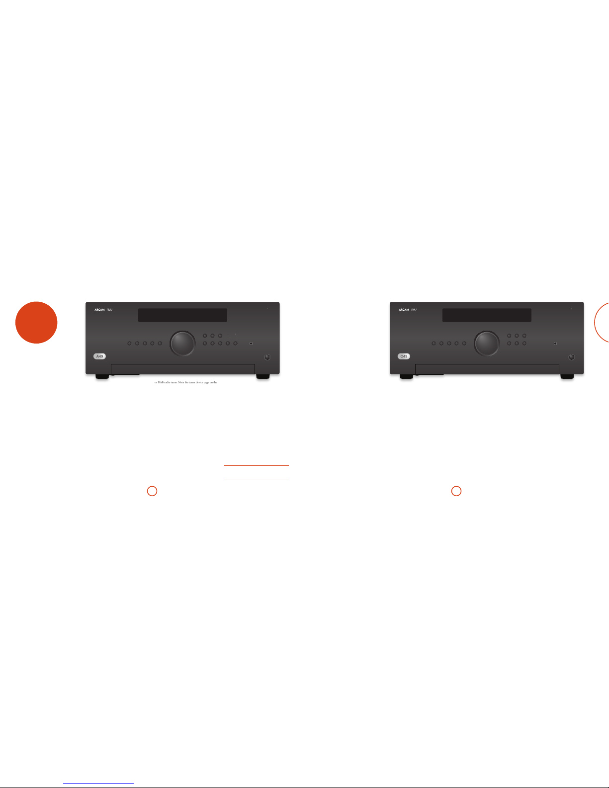
PHONO 20
PHONO AUX CD TUNER SAT
MUTE DISPLAY BALANCE
BD PVR AV SP1 SP2 PHONES
POWER
POWER / STANDBY
Selecting an audio source
Audio sources may be selected from the front panel
buttons (PHONO, Aux, CD, TUNER, SAT, BD, PVR, AV), or the
remote control (PHONO, AUX, CD, TUN, SAT, BD, PVR, AV).
In each case, the source is selected from the input
sockets with the corresponding name.
Audio inputs
Although the inputs are labelled for specic devices, all
have the same characteristics and each may be used with
any line-level product. e exception is the PHONO (MM)
input (see pages20-21 for the specication).
AUX (XLR)
Intended for the balanced analogue outputs from a
source, for example the Arcam D33. e balanced
inputs can also be assigned to any other input key on
the remote. Either use the MENU button on the remote to
access the setup menu, or press the front panel BD and
BALANCE buttons simultaneously and use the control
knob to change the setting. e front panel display shows
(e.g.) XLR CD. In this example, when the CD button on
the remote is pressed, the XLR inputs will be selected. So
the original input is still available, when the AUX button is
pushed, the CD input will be selected.
TUNER
Intended for the analogue outputs from an FM, AM
Phono input
Phono-level input
e A49/C49 provides a pre-amplication stage to treat
the low-voltage output from a MM (moving magnet)
cartridge. Input specications are given on pages 20 - 21.
Output volume is shown on the front display as
PHONO 20, for example.
Line-level phono input
e phono input may be changed from line-level to
phono-level. Either use the MENU button on the remote to
access the setup menu, or press the front panel PHONO
and BALANCE buttons simultaneously and use the control
knob to change the setting. e front panel display shows
LINE- OFF (i.e. phono) or LINE- ON respectively.
If you wish to use an external phono amplier, connect
its output to the PHONO (MM) input, but make sure that
LINE- ON is selected, since a phono amplier produces
line-level input.
With the input dened in this way, output volume is
shown on the front display as LINE- 20, for example.
WARNING: NEVER play a standard line-level source into the
phono input when set to LINE-OFF. This would result in serious
damage to both your amplier and speakers due to the extra
gain that is applied and would not be covered under warranty.
A49/C49
operation
PHONO 20
PHONO AUX CD TUNER SAT
MUTE DISPLAY BALANCE
BD PVR AV PHONES
POWER
POWER / STANDBY
PM 50. When at the default level, a > will be shown just
in front of the level indication.
Connecting to an additional
power amplifier
e A49/C49 provides a pair of unbalanced pre-outs on
standard RCA phono connectors and a set of balanced
pre-outs on XLR connectors to allow connection to
an additional power amplier to create a bi-amplied
setup.
Most audio ampliers, including the Arcam P49/
P349, will connect to the RCA phono connectors
using standard interconnect cables. is connection is
recommended for short cable runs. Connect to the PRE
IN connection of the power amplifer
If however your amplier has balanced connections,
you may use the balanced XLR output. is connection
provides greater rejection from electrical interference
and is useful when cables are long (more than a few
metres) or in electrically-noisy environments. Balanced
connections also have the ability to reject ‘hum’ caused
by ‘ground loops’. Connect to the PRE IN connection of
your power amplier.
Recording an audio source
e A49/C49 allows you to record and monitor the
sound from any connected source.
e back panel REC OUT socket can be connected to the
input sockets of your recording device (these are usually
labelled RECORD or IN).
To record from a particular source, press the
appropriate source button (for example, TUNER).
Adjusting the balance
e balance setting allows you to increase the volume of
one channel (le or right) relative to the other. Altering
the balance may help to restore the stereo image for an
o-centre listening position.
Balance can be adjusted from the front panel or from
the remote control. Press the BALANCE button (or BAL
on the CR902) to view the current setting, then use
the control knob (or the +/ buttons on the remote)
to change the setting – from L9 to R9, via the neutral
value 0.
Speaker Control
e SP1 and SP2 switches (A49 only) enable and disable
the respective speaker outputs. e LED will be lit if the
speakers are enabled.
Listening
Volume control
Use the control knob (or the +/ buttons on the remote)
to change the volume. Turn the knob clockwise to
increase the volume, anti-clockwise to reduce it.
Listening using headphones
e headphones socket (PHONES) accepts headphones
with an impedance rating between 8Ω and 2kΩ, tted
with a 3.5mm stereo jack plug.
e pre-amp outputs and speakers are muted when
headphones are plugged in and the front panel display
shows HEADPHONE.
e headphones socket is always active, unless output
has been muted.
Muting output
e output of the A49/C49 can be silenced by pressing
MUTE on the front panel (or -on the remote control).
If the unit is muted, the power light changes to orange
and the source is shown on the front display panel (e.g.
PVR MT).
Press MUTE/-for a second time (or change the volume)
to cancel mute.
Connecting to a source
component with a balanced
output
In addition to the seven single end (RCA) inputs, the
A49/C49 provides a single balanced input on female
XLR connectors.
If your source component (such as the Arcam D33)
has balanced audio outputs you may wish to use this
connection instead of the single ended inputs. is type
of connection provides greater rejection from electrical
interference and is useful when cables are long (more
than a few metres) or in electrically-noisy environments.
Balanced connections also have the ability to reject
‘hum’ caused by ‘ground loops’.
Processor mode
Processor mode can be assigned to any input. In this
mode, the A49/C49 is set to a xed level. Use MENU
button on the remote and then use the control knob to
change the setting. e front panel display shows (e.g.)
PROC- AV.
When this input is selected, the volume display will show
PM instead of the volume level.
To alter the level use the MENU button on the remote to
access the setup menu then use the control knob to
change the setting. e front panel display shows (e.g.)

E-13E-12
English
SP1 and SP2
ese buttons allow you to switch the speakers on and
o.
e LED above each button glows green to indicate
which speakers are currently selected. If you are using
the bi-wiring conguration described on page15, both
SP1 and SP2 must be switched on.
Note that when both lights are out, the amplier will
appear not to work, as all speakers are switched o.
SP1 SP2
POWER
POWER / STANDBY
Switching on
e POWER button switches the unit on and o.
e power light (next to the ‘POWER / STANDBY’
text) indicates the state of the amplier: it changes from
red to orange then green if mains power is connected
and the unit is switched on.
P49/P349
operation CR902 remote
control
e CR902 is pre-programmed for use with the
A49.
Make sure the two AAA batteries supplied are
installed before attempting to use the remote
control.
A. With the CR902 remote face-down, press down
on the non-slip indentations of the battery
compartment cover and slide the cover o.
B. Insert the two ‘AAA’ batteries supplied. Take
care to insert the batteries in the right direction
by following the ‘+’ and ‘–’ marks in the battery
compartment.
C. Slide the battery compartment cover back and
lock it in place with a click.
e CR902 requires a clear line of sight to the front
panel display of A49 to ensure reliable operation.
AUDIO
SACD
MENU
FM MONO P/TUNE STORE
INFO
BD
CR902
RTN
Alternative code selection
In the rare sitatuation that the CR902 remote control
happens to operate another device in the room, the
IR code can be changed to an alternative RC5 system
number.
To change the remote control to the alternate code:
Press and hold the AMP key and press 1and then 9.
To restore to the original code:
Press and hold the AMP key and press 1and then 6.
Note: the selection of the alternate codes is reset when
the batteries are changed.
In addition to changing the remote handset, the A49/
C49 unit must also be recongured to respond to the
alternate codes. Either use the MENU button on the remote
to access the setup menu, or press the front panel SAT,
CD and MUTE buttons simultaneously and use the control
knob to change the setting. e front panel display shows
(e.g.) IR SYS 16.

E-15E-14
English
AMP Device Mode
e ADevice Mode button congures the CR902 to
control your Arcam amplier. Pressing this button does
not aect the currently selected input on the amplier.
P
Toggles power between standby and on
DISP Cycles through the front panel display’s
brightness options
MENU Displays the amplier setup menu on the
front panel
Navigate menus
Oconrms a selection
@
Toggles the mute function of the amplier
VOL-
VOL+
Decrease () and increase (+) amplier
volume
SP1 Toggles Speaker 1 output
SP2 Toggles Speaker 2 output
BAL Adjusts the balance between the le and
right audio channel
TUN Device Mode
e TDevice Mode button congures the CR902 to
control the tuner functions of Arcam tuners.
P
Toggles power between standby and on
0…9e numeric keys are used to store and
recall presets
DISP Cycles through the front panel display’s
brightness options
INFO Cycle through dierent information
display modes
)Rewind iPod
(Fast forward iPod
]Preset down/Sirius category down/iPod
track back
[Preset up/Sirius category up/iPod track
forward
#Stop iPod
$Play / pause iPod
&Play / pause iPod
MENU Displays the tuner setup menu on the front
panel
' , Preset up / down, iPod track back / forward
< > Decrement / increment tuning frequency
OConrm a selection
FM MONO Toggle FM mode between mono and stereo
reception
P/TUNE Enter/Exit Preset recall mode
STORE Enter/Exit Preset store mode
BAND Cycles through available tuner bands
CD Device Mode
e cDevice Mode button congures the CR902 to
control the CD functions of Arcam CD players.
PToggles power between standby and on
!Open/close disc tray
0…9
e numeric keys allow direct access to
individual tracks on a disc. To select a track
press the corresponding keypad button.
For tracks greater than 9, enter the digits
in sequence. For example, to play track 15,
press 1, then press 5.
DISP Cycles through the front panel display’s
brightness options
MODE Changes the available display modes on the
CD player
)Fast rewind
(Fast forward
]Skip back to the start of the current/
previous track
[Skip forwards to the start of the next track
#Stop playback
$Play
&Toggles pause of playback
MENU Enter a track in a programmed track list
Navigates track listings if supported by the
player
Oselects the currently highlighted track if
supported by the player
SHUFF Toggles random (‘shue’) play on and o
RPT
Repeat playback of the disc or pre-
programmed selection of tracks. To repeat
a particular track, select that track and press
RPT twice. To cancel, press RPT a third time.
SACD Toggles between selecting the HD and CD
layer of SACD disc
BD Device Mode
e BDevice Mode button congures the CR902 to
control the BD functions of Arcam BD players.
PToggles power between standby and on
!Open/close disc tray
0…9
e numeric keys allow direct access to
individual tracks on a disc. To select a track
press the corresponding keypad button.
For tracks greater than 9, enter the digits
in sequence. For example, to play track 15,
press 1, then press 5.
DISP Cycles through the front panel display’s
brightness options
MODE Changes the available display modes on the
BD player
)Fast rewind
(Fast forward
]Skip back to the start of the current/
previous track
[Skip forwards to the start of the next track
#Stop playback
$Play
&Toggles pause of playback
AUDIO Changes audio decode format (Dolby
Digital, DTS, etc.).
MENU Activates BD player menu.
Navigates track listings if supported by the
player
Oselects the currently highlighted track if
supported by the player
.Returns navigation to the top level of the
menu (‘Home’).
RTN When navigating a menu, press this key to
return to the previous screen or selection
SHUFF Toggles random (‘shue’) play on and o
RPT
Repeat playback of the disc or pre-
programmed selection of tracks. To repeat
a particular track, select that track and press
RPT twice. To cancel, press RPT a third time.
SACD Toggles between selecting the HD and CD
layer of SACD disc
loudspeakers
Normal single wiring
For single wiring, we recommend that you use the
SPEAKER 1 set of terminals on your amplier. If each
speaker has more than one pair of connecting terminals,
use the terminals labelled LF or ‘Low Frequency’.
Connect the red positive terminal of the right speaker
connection on the amplier (labelled R+) to the positive
terminal of your right speaker. Similarly, connect the
black negative terminal of the right speaker connection
on the amplier (labelled R) to the negative terminal
of your speaker. Repeat the process for the le speaker,
using the terminals labelled L+ and L on the amplier.
WARNING: If your speakers support bi-wiring, there will be a
strip of conductive metal connecting the low-frequency (LF)
terminals to the high-frequency (HF) terminals; this MUST NOT
BE REMOVED in a single-wired system.
Notes on making speaker connections
< Do not make any connections to any amplier while it is switched on. We recommend that your
amplier is completely disconnected from the mains supply before starting.
< Before switching your amplier(s) on for the rst time aer connecting to speakers, please check all
connections thoroughly. Ensure that bare wires or cables are not touching each other or the amplier’s
chassis (which could cause short circuits), and that you have connected positive (+) to positive and
negative (–) to negative. Be sure to check the wiring for both the amplier and the speaker.
< Aer making connections: switch the amplier(s) on, select a source signal, then gradually increase the
volume to the required listening level.
< If you are unsure as to how your system should be connected, or need advice on bi-amping, please
contact your Arcam dealer who will be happy to help you.
Connecting
loudspeakers
ere are many dierent ways of connecting your
loudpeakers to your A49 or P49/P349 and the following
section describes how to connect and congure the
loud speakers and amplier for the most common
congurations.
PHONO
GROUND
ONLY
PHONO
(MM) CD TUNER SAT BD PVR AV
RECORD
OUT
PRE
OUT
R
4–16 OHMS. CLASS 2 WIRING
SPEAKER 1 SPEAKER 2
L
4–16 OHMS. CLASS 2 WIRING
SPEAKER 2 SPEAKER 1
AUX R AUX L PRE OUT R PRE OUT L TRIGGER OUT
6V 1A12V 1.5A
ACCESSORY
POWER
110-120V/220-240V ~ 50-60 Hz
350W MAX
POWER INLET
SUPPLY
VOLTAGE
SWITCH POSITIONS
115 = 110 - 120V~
230 = 220 - 240V~
LF
HF
LF
HF
A49
An A49 connected to speakers using single wiring.
R L
Bi-wiring
Bi-wiring is performed in the same way as single wiring
except that, a pair of cables are used to connect the
amplier to each speaker.
Follow the instructions given for single wiring; then
perform the same actions, this time connecting the
SPEAKER 2 set of terminals on your amplier to the
terminals labelled HF or ‘High Frequency’ for each
speaker.
WARNING: Speakers that support bi-wiring have a strip of
metal that connects the low frequency (LF) terminals to the
high frequency (HF) terminals. This MUST BE REMOVED in a
bi-wired system.
PHONO
GROUND
ONLY
PHONO
(MM) CD TUNER SAT BD PVR AV
RECORD
OUT
PRE
OUT
R
4–16 OHMS. CLASS 2 WIRING
SPEAKER 1 SPEAKER 2
L
4–16 OHMS. CLASS 2 WIRING
SPEAKER 2 SPEAKER 1
AUX R AUX L PRE OUT R PRE OUT L TRIGGER OUT
6V 1A12V 1.5A
ACCESSORY
POWER
110-120V/220-240V ~ 50-60 Hz
350W MAX
POWER INLET
SUPPLY
VOLTAGE
SWITCH POSITIONS
115 = 110 - 120V~
230 = 220 - 240V~
LF
HF
LF
HF
A49
An A49 connected to two sets of speakers using bi-wiring.
R L
Remove
metal strip
Remove
metal strip

E-17E-16
English
Bi-amping
Bi-amping requires the use of two ampliers per
channel. Normally, your A49 is used to drive the high-
frequency (treble) speakers, while a power-amplier
(such as a P49/P349) is used for the lower (bass)
frequencies.
Connect your A49 to the speakers as described for
single wiring, with the exception that the A49 should be
connected to the speaker terminals labelled HF or ‘High
Frequency’.
en connect the power amplier (P49/P349, for
example) to the LF or ‘Low Frequency’ terminals, as in
the diagram. A pair of audio interconnect cables are also
required to connect the pre-amp outputs of the A49 to
the power amp inputs of the P49/P349.
e interconnects can be either XLR (recommended for
longer cable runs) or phono (RCA). Set the INPUT switch
on the P49/P349 to the appropriate setting for the cables
used.
WARNING: the strip of metal on the speakers connecting
the low frequency (LF) terminals to the high frequency (HF)
terminals MUST BE REMOVED. Failure to do so will result
in damage to both ampliers, which will not normally be
covered under warranty.
To allow the power state of the P49/P349 to be
controlled by the A49 please connect the TRIGGER OUT
to the TRIGGER IN using a mono 3.5mm jack lead – not
supplied.
An A49 and P49 connected to speakers using bi-amping.
PHONO
GROUND
ONLY
PHONO
(MM) CD TUNER SAT BD PVR AV
RECORD
OUT
PRE
OUT
R
4–16 OHMS. CLASS 2 WIRING
SPEAKER 1 SPEAKER 2
L
4–16 OHMS. CLASS 2 WIRING
SPEAKER 2 SPEAKER 1
AUX R AUX L PRE OUT R PRE OUT L TRIGGER OUT
6V 1A12V 1.5A
ACCESSORY
POWER
110-120V/220-240V ~ 50-60 Hz
350W MAX
POWER INLET
SUPPLY
VOLTAGE
SWITCH POSITIONS
115 = 110 - 120V~
230 = 220 - 240V~
ST/BRIDGE/DM
MODE
XLR/RCA
INPUT
25dB/31dB
GAIN
L
R
PRE
IN
PRE
OUT
R
4–16 OHMS. CLASS 2 WIRING
SPEAKER 1 SPEAKER 2
L
4–16 OHMS. CLASS 2 WIRING
SPEAKER 2 SPEAKER 1
PRE IN R PRE IN L
110-120V/220-240V ~ 50-60 Hz
350W MAX
POWER INLET
SUPPLY
VOLTAGE
SWITCH POSITIONS
115 = 110 - 120V~
230 = 220 - 240V~
TRIGGER IN
TRIGGER OUT
LF
HF
LF
HF
R L
A49
P49
Remove
metal strip
Remove
metal strip
Make sure INPUT
switch matches wired
configuration (XLR or RCA)
Make sure MODE
switch is set to ST
Make sure GAIN
switch is set to 31dB
NOTE: Units canbe interconnected via XLR or RCA.
Both versions shown for illustration purposes only.
ST/BRIDGE/DM
MODE
ST/BRIDGE/DM
MODE
ST/BRIDGE/DM
MODE
XLR/RCA
INPUT
XLR/RCA
INPUT
25dB/31dB
GAIN
25dB/31dB
GAIN
ST/BRIDGE/DM
MODE
ST/BRIDGE/DM
MODE
ST/BRIDGE/DM
MODE
XLR/RCA
INPUT
XLR/RCA
INPUT
25dB/31dB
GAIN
25dB/31dB
GAIN
ST/BRIDGE/DM
MODE
ST/BRIDGE/DM
MODE
ST/BRIDGE/DM
MODE
XLR/RCA
INPUT
XLR/RCA
INPUT
25dB/31dB
GAIN
25dB/31dB
GAIN
LF
HF
LF
HF
Bridged mode - P49 only
In bridged mode only the L+ and R+ outputs of SPEAKER
1are active.
WARNING: Do not make any connections to the other speaker
terminals, doing so will severely damage your amplier.
If each speaker has more than one pair of connecting
terminals, use the terminals labelled LF or ‘Low
Frequency’.
To drive your right speaker, select one of the P49
ampliers and connect the red positive speaker terminal
labelled SPEAKER 1 L+ to the positive LF terminal of your
right speaker.
R
A C49 pre-amp and two P49 power amps in bridged configuration.
PHONO
GROUND
ONLY
PHONO
(MM) CD TUNER SAT BD PVR AV
RECORD
OUT
PRE
OUT
AUX R AUX L PRE OUT R PRE OUT L TRIGGER OUT
6V 1A12V 1.5A
ACCESSORY
POWER
110-120V/220-240V ~ 50-60 Hz
350W MAX
POWER INLET
SUPPLY
VOLTAGE
SWITCH POSITIONS
115 = 110 - 120V~
230 = 220 - 240V~
ST/BRIDGE/DM
MODE
XLR/RCA
INPUT
25dB/31dB
GAIN
L
R
PRE
IN
PRE
OUT
R
4–16 OHMS. CLASS 2 WIRING
SPEAKER 1 SPEAKER 2
L
4–16 OHMS. CLASS 2 WIRING
SPEAKER 2 SPEAKER 1
PRE IN R PRE IN L
TRIGGER IN
110-120V/220-240V ~ 50-60 Hz
350W MAX
POWER INLET
SUPPLY
VOLTAGE
SWITCH POSITIONS
115 = 110 - 120V~
230 = 220 - 240V~
TRIGGER OUT
L
Similarly, connect the red positive speaker terminal
labelled SPEAKER 1 R+ to the negative LF terminal of your
right speaker.
Repeat the above procedure to connect the second P49
amplier to the le speaker.
WARNING: Make absolutely sure you have used the correct
SPEAKER 1L+ and R+ terminals.
In this setup only one interconnect is required to each
power amplifer and it should be connected to the PRE
IN L input.
C49
P49 P49
e interconnects can be either XLR (recommended for
longer cable runs) or phono (RCA). Set the INPUT switch
on the P49 to the appropriate setting for the cables used.
WARNING: If your speakers support bi-wiring, there will be a
strip of conductive metal connecting the low-frequency (LF)
terminals to the high-frequency (HF) terminals; this MUST NOT
BE REMOVED in a bridged mode system.
To allow the power state of the P49 to be controlled by
the A49 please connect the TRIGGER OUT to the TRIGGER
IN using a mono 3.5mm jack lead – not supplied.
Make sure MODE
switch is set to BRIDGE
on both amps
ST/BRIDGE/DM
MODE
ST/BRIDGE/DM
MODE
ST/BRIDGE/DM
MODE
XLR/RCA
INPUT
XLR/RCA
INPUT
25dB/31dB
GAIN
25dB/31dB
GAIN
NOTE: Units canbe interconnected via XLR or RCA.
Both versions shown for illustration purposes only.
Make sure INPUT
switch matches wired
configuration (XLR or RCA)
on both amps
ST/BRIDGE/DM
MODE
ST/BRIDGE/DM
MODE
ST/BRIDGE/DM
MODE
XLR/RCA
INPUT
XLR/RCA
INPUT
25dB/31dB
GAIN
25dB/31dB
GAIN
Make sure GAIN
switch is set to 31dB
on both amps
ST/BRIDGE/DM
MODE
ST/BRIDGE/DM
MODE
ST/BRIDGE/DM
MODE
XLR/RCA
INPUT
XLR/RCA
INPUT
25dB/31dB
GAIN
25dB/31dB
GAIN

E-19E-18
English
ST/BRIDGE/DM
MODE
XLR/RCA
INPUT
25dB/31dB
GAIN
L
R
PRE
IN
PRE
OUT
R
4–16 OHMS. CLASS 2 WIRING
SPEAKER 1 SPEAKER 2
L
4–16 OHMS. CLASS 2 WIRING
SPEAKER 2 SPEAKER 1
PRE IN R PRE IN L
110-120V/220-240V ~ 50-60 Hz
350W MAX
POWER INLET
SUPPLY
VOLTAGE
SWITCH POSITIONS
115 = 110 - 120V~
230 = 220 - 240V~
TRIGGER IN
TRIGGER OUT
LF
HF
PHONO
GROUND
ONLY
PHONO
(MM) CD TUNER SAT BD PVR AV
RECORD
OUT
PRE
OUT
AUX R AUX L PRE OUT R PRE OUT L TRIGGER OUT
6V 1A12V 1.5A
ACCESSORY
POWER
110-120V/220-240V ~ 50-60 Hz
350W MAX
POWER INLET
SUPPLY
VOLTAGE
SWITCH POSITIONS
115 = 110 - 120V~
230 = 220 - 240V~
LF
HF
Dual mono - P49 only
Dual mono requires the use of a power amplier for
each channel.
We recommend that you use the SPEAKER 1 L set
of terminals on your P49 power amps for the low
frequencies and the SPEAKER 2 R set of terminals for the
high frequencies.
On one of the P49’s, connect the red positive speaker
terminal labelled SPEAKER 1 L+ to the positive LF terminal
of your right speaker. Similarly, connect the black
negative speaker terminal labelled SPEAKER 1 L to the
negative LF terminal of your right speaker. Repeat this
process for the le speaker, using the terminals labelled
SPEAKER 1 L+ and L on the other P49 power amp.
On the rst P49, connect the red positive speaker
terminal labelled SPEAKER 1 R+ to the positive HF
terminal of your right speaker. Similarly, connect the
black negative speaker terminal labelled SPEAKER 1 R to
the negative HF terminal of your speaker. Repeat this
process for the le speaker, using the terminals labelled
SPEAKER 1 R+ and R on the second P49.
In this setup only one interconnect is required to each
power amplifer and it should be connected to the
PRE IN L input. e interconnects can be either XLR
(recommended for longer cable runs) or phono (RCA).
Set the INPUT switch on the P49’s to the appropriate
setting for the cables used.
Note: PRE IN R has no function in this arrangement.
WARNING: the strip of metal on the speakers connecting
the low frequency (LF) terminals to the high frequency (HF)
terminals MUST BE REMOVED. Failure to do so will result
in damage to both ampliers, which will not normally be
covered under warranty.
To allow the power state of the P49 to be controlled by
the A49 please connect the TRIGGER OUT to the TRIGGER
IN using a mono 3.5mm jack lead – not supplied.
R
A C49 pre-amp and two P49 power amps in dual mono configuration.
ST/BRIDGE/DM
MODE
XLR/RCA
INPUT
25dB/31dB
GAIN
L
R
PRE
IN
PRE
OUT
R
4–16 OHMS. CLASS 2 WIRING
SPEAKER 1 SPEAKER 2
L
4–16 OHMS. CLASS 2 WIRING
SPEAKER 2 SPEAKER 1
PRE IN R PRE IN L
110-120V/220-240V ~ 50-60 Hz
350W MAX
POWER INLET
SUPPLY
VOLTAGE
SWITCH POSITIONS
115 = 110 - 120V~
230 = 220 - 240V~
TRIGGER IN
TRIGGER OUT
L
C49
P49 P49
Remove
metal strip
Remove
metal strip
Make sure MODE
switch is set to DM
on both amps
Make sure INPUT
switch matches wired
configuration (XLR or RCA)
on both amps
ST/BRIDGE/DM
MODE
ST/BRIDGE/DM
MODE
ST/BRIDGE/DM
MODE
XLR/RCA
INPUT
XLR/RCA
INPUT
25dB/31dB
GAIN
25dB/31dB
GAIN
NOTE: Units canbe interconnected via XLR or RCA.
Both versions shown for illustration purposes only.
Make sure GAIN
switch is set to 31dB
on both amps
ST/BRIDGE/DM
MODE
ST/BRIDGE/DM
MODE
ST/BRIDGE/DM
MODE
XLR/RCA
INPUT
XLR/RCA
INPUT
25dB/31dB
GAIN
25dB/31dB
GAIN
ST/BRIDGE/DM
MODE
ST/BRIDGE/DM
MODE
ST/BRIDGE/DM
MODE
XLR/RCA
INPUT
XLR/RCA
INPUT
25dB/31dB
GAIN
25dB/31dB
GAIN
troubleshooting
Sound cuts-out unexpectedly
If the temperature of the internal heatsink rises above
a safe level, then a thermal cut-out inside the amplier
operates to protect the unit and the protection system
temporarily removes power to the speakers. e system
will reset itself as the heatsink cools down.
< With two pairs of low-impedance speakers
connected (6Ω or less), overloads are more likely.
Overloading the amplier may cause it to shut
down because of overheating.
< Note that, due to the high output voltage from
some CD players, it is possible to drive your
amplier at full power even though the volume is
not set at maximum.
If you are having trouble with your amplier, check the
following items.
No sound
Check the following:
< e amplier is switched on.
< e A49/C49 is not muted (i.e. MT (mute) is not
shown on the display panel; the power LED is
showing green, not orange or red).
< e selected source going in to the A49/C49 is
generating audio (e.g., if CD is selected, then the
CD is playing).
< e speaker outputs on the A49/P49/P349 are
active and the appropriate speaker LED is showing
green.
No remote control
Check the following:
< Check the remote control with fresh batteries.
< Ensure that the amplier and remote are both set to
the same control code - see page17.
< If the volume does not operate for a selected input,
check that processor mode has not been selected for
that input - see page12.

E-21E-20
English
Continuous power output (20Hz—20kHz at 0.2% THD), per channel
Both channels, 8Ω, 20Hz—20kHz 200W
Single channel, 4Ω, at 1kHz 400W
Harmonic distortion, 80% power, 8Ω at 1kHz 0.001%
Inputs
Phono (MM) cartridge:
Input sensitivity at 1kHz 5mV
Input impedance 47kΩ + 100pF
Frequency response (ref. RIAA curve) 20Hz—20kHz ± 1dB
Signal/noise ratio (Awtd) 50W, ref. 5mV input 80dB
Overload margin, 5mV at 1kHz 20dB
Inputs: RCA type XLR type
Nominal sensitivity 1V 2V
Input impedance 10kΩ 10kΩ
Maximum input 8V 15V
Frequency response 20Hz—20kHz ± 0.05dB
Signal/noise ratio (Awtd) 50W, ref. 1V/2V input 105dB
Preamplier output RCA type XLR type
Nominal output level 1.15V 2.3V
Output impedance 47Ω 200Ω
Headphones output
Maximum output level into 600Ω 4Vrms
Output impedance 1Ω
Load range 16Ω—2kΩ
Accessory power output
Two accessory power cables supplied, provides two
2.1mm DC connectors
6V, 1A
12V, 1.5A
General
Mains voltage 110–120V~ or 220–240V~
Power consumption (maximum) 1kW
Dimensions W x D x H (including feet) 433 x 425 x 171mm
Weight (net) 19.7kg
Weight (packed) 21.4kg
Supplied accessories Mains lead
CR902 remote control
2 x AAA batteries
Accessory power cable
E&OE
NOTE: All specication values are typical unless otherwise stated.
A49
specications
Continual improvement policy
Arcam has a policy of continual improvement for its
products. is means that designs and specications
are subject to change without notice.
Inputs
Phono (MM) cartridge:
Input sensitivity at 1kHz 5mV
Input impedance 47kΩ + 100pF
Frequency response (ref. RIAA curve) 20Hz—20kHz ± 1dB
Signal/noise ratio (Awtd) 50W, ref. 5mV input 80dB
Overload margin, 5mV at 1kHz 20dB
Inputs: RCA type XLR type
Nominal sensitivity 1V 2V
Input impedance 10kΩ 10kΩ
Maximum input 4.6V 8.2V
Frequency response 20Hz—20kHz ± 0.05dB
Signal/noise ratio (Awtd) 50W, ref. 1V input 105dB
Preamplier output RCA type XLR type
Nominal output level 1.15V 2.3V
Output impedance 47Ω 200Ω
Headphones output
Maximum output level into 600Ω 4Vrms
Output impedance 1Ω
Load range 16Ω—2kΩ
Accessory power output
Two accessory power cables supplied, provides two
2.1mm DC connectors
6V, 1A
12V, 1.5A
General
Mains voltage 110–120V~ or 220–240V~
Power consumption (maximum) 300W
Dimensions W x D x H (including feet) 433 x 410 x 171mm
Weight (net) 8.7kg
Weight (packed) 10.4kg
Supplied accessories Mains lead
CR902 remote control
2 x AAA batteries
Accessory power cable
E&OE
NOTE: All specication values are typical unless otherwise stated.
C49
specications
Continual improvement policy
Arcam has a policy of continual improvement for its
products. is means that designs and specications
are subject to change without notice.

E-23E-22
English
Continuous power output (20Hz—20kHz at 0.2% THD), per channel
Both channels, 8Ω, 20Hz—20kHz 200W
Single channel, 4Ω, at 1kHz 400W
Harmonic distortion, 80% power, 8Ω at 1kHz 0.001%
Inputs
PWR IN input: RCA type XLR type
Nominal sensitivity for 200W / 8Ω 1.15V 2.3V
Input impedance 10kΩ 10kΩ
Frequency response 20Hz—20kHz ± 0.05dB
Signal/noise ratio (Awtd) ref 50W / 8Ω 110dB
General
Mains voltage 110–120V~ or 220–240V~
Power consumption (maximum) 1kW
Dimensions W x D x H (including feet) 433 x 425 x 171mm
Weight (net) 18.0kg
Weight (packed) 19.7kg
Supplied accessories Mains lead
E&OE
NOTE: All specication values are typical unless otherwise stated.
P49
specications
Continual improvement policy
Arcam has a policy of continual improvement for its
products. is means that designs and specications
are subject to change without notice.
Continuous power output (20Hz—20kHz at 0.2% THD), per channel
ree channels, 8Ω, 20Hz—20kHz 180W
Two channels, 8Ω, 20Hz—20kHz 200W
Single channel, 8Ω, at 1kHz 220W
Single channel, 4Ω, at 1kHz 400W
Harmonic distortion, 80% power, 8Ω at 1kHz 0.001%
Inputs
PWR IN input: RCA type XLR type
Nominal sensitivity for 200W / 8Ω 1.15V 2.3V
Input impedance 10kΩ 10kΩ
Frequency response 20Hz—20kHz ± 0.05dB
Signal/noise ratio (Awtd) ref 50W / 8Ω 110dB
General
Mains voltage 110–120V~ or 220–240V~
Power consumption (maximum) 1kW
Dimensions W x D x H (including feet) 433 x 425 x 171mm
Weight (net) 18.0kg
Weight (packed) 19.7kg
Supplied accessories Mains lead
E&OE
NOTE: All specication values are typical unless otherwise stated.
P349
specications
Continual improvement policy
Arcam has a policy of continual improvement for its
products. is means that designs and specications
are subject to change without notice.

E-24
product
guarantee
Correct disposal of this product
is marking indicates that this
product should not be disposed
with other household waste
throughout the EU.
To prevent possible harm to the
environment or human health from
uncontrolled waste disposal and to
conserve material resources, this product should be
recycled responsibly.
To dispose of your product, please use your local
return and collection systems or contact the retailer
where the product was purchased.
Worldwide Guarantee
is entitles you to have the unit repaired free of charge, during the rst two years aer
purchase, provided that it was originally purchased from an authorised Arcam dealer.
e Arcam dealer is responsible for all aer-sales service. e manufacturer can take no
responsibility for defects arising from accident, misuse, abuse, wear and tear, neglect or
through unauthorised adjustment and/or repair, neither can they accept responsibility
for damage or loss occurring during transit to or from the person claiming under the
guarantee.
The warranty covers:
Parts and labour costs for two years from the purchase date. Aer two years you must
pay for both parts and labour costs. e warranty does not cover transportation costs
at any time.
Claims under guarantee
is equipment should be packed in the original packing and returned to the dealer from
whom it was purchased. It should be sent carriage prepaid by a reputable carrier – not
by post. No responsibility can be accepted for the unit whilst in transit to the dealer or
distributor and customers are therefore advised to insure the unit against loss or damage
whilst in transit.
For further details contact Arcam at:
Arcam Customer Support Department,
Unit 15, Pembroke Avenue, Waterbeach, CAMBRIDGE, CB25 9QP, England
or via www.arcam.co.uk.
Problems?
If your Arcam dealer is unable to answer any query regarding this or any other Arcam
product please contact Arcam Customer Support at the above address and we will do our
best to help you.
On-line registration
You can register your product on-line at www.arcam.co.uk.

Français
PHONO
PHONO AUX CD TUNER SAT
MUTE DISPLAY BALANCE
BD PVR AV SP1 SP2 PHONES
POWER
POWER / STANDBY
PHONO
PHONO AUX CD TUNER SAT
MUTE DISPLAY BALANCE
BD PVR AV PHONES
POWER
POWER / STANDBY
SP1 SP2
POWER
POWER / STANDBY
MANUEL Amplicateur intégré / Préamplicateur / Amplicateur de puissance
A49/C49/P49/P349

Français
F-3F-2
conseils de
sécurité
ATTENTION : Pour réduire le risque d’électrocution, ne retirez pas le couvercle (ou l’arrière). L’appareil ne contient aucune pièce pouvant
être réparée par l’utilisateur. Confiez toute réparation à du personnel d’entretien qualifié.
MISE EN GARDE: Pour réduire le risque d’incendie ou d’électrocution, protégez cet appareil de la pluie ou de l’humidité.
L’éclair avec une flèche dans un triangle équilatéral permet d’avertir l’utilisateur de la présence de tensions dangereuses non isolées
à l’intérieur de l’appareil, d’une ampleur suffisante pour constituer un risque d’électrocution sur les personnes.
Le point d’exclamation dans un triangle équilatéral permet d’avertir l’utilisateur de la présence de consignes importantes sur le
fonctionnement et l’entretien (réparations) dans la documentation livrée avec l’appareil.
ATTENTION : Au Canada et aux Etats-Unis, pour éviter tout risque d’électrocution, faites correspondre la lame la plus large de la fiche à la
fente la plus large de la prise et insérez la fiche entièrement dans la prise.
Produit de classe II
Cet équipement est une Classe II ou un
appareil électrique à double isolation. Il
a été conçu de telle manière à ce qu'il ne
nécessite pas de branchement de sécurité à une
prise de terre.
Mise en garde
La prise principale/ le coupleur de l'appareil est
utilisé pour débrancher l'appareil et doit rester
facilement accessible.
Instructions importantes de
sécurité
1. Lisez ces instructions.
2. Conservez ces instructions.
3. Respectez toutes les mises en garde.
4. Suivez l’ensemble des instructions.
5. N’utilisez pas cet appareil près d’une source d’eau.
6. Nettoyez uniquement avec un chion sec.
7. Ne bloquez pas les ouvertures d’aération. Procédez
à l’installation conformément aux recommandations
du fabricant.
8. N’installez pas l’appareil près de sources de
chaleur, comme des radiateurs, des grilles de
chauage, des fours ou autres appareils (y compris
des amplicateurs) produisant de la chaleur.
9. Ne détournez pas la protection de la prise
polarisée ou de terre.
Une prise polarisée dispose de deux lames, dont l’une
plus large que l’autre. Une prise de terre dispose de deux
lames et d’une troisième broche de mise à la terre. La
lame la plus large ou la troisième broche correspond
à un dispositif de protection. Si la che fournie ne
correspond pas à votre installation électrique, veuillez
vous adresser à un électricien pour faire remplacer la
prise obsolète.
10. Installez le câble électrique de telle sorte qu’il
ne puisse pas être piétiné ou écrasé, notamment au
niveau des ches, des prises et des points de sortie de
l’appareil.
11. Utilisez uniquement des câbles/accessoires
conformes aux recommandations du fabricant.
12. Utilisez uniquement un
meuble à roulettes, un support, un
trépied, des xations ou une table
recommandé(e) par le fabricant ou
livré(e) avec l’appareil.
En cas d’utilisation d’un meuble à
roulettes, déplacez le meuble/appareil
avec précaution pour éviter de le renverser, ce qui
pourrait entraîner des blessures.
13. Débranchez l’appareil en cas d’orage ou lorsque
vous ne l’utiliserez pas sur une période prolongée.
14. Conez les réparations à un technicien qualié.
Il est nécessaire de faire réparer l’appareil s’il a été
endommagé d’une manière ou d’une autre, par exemple
si le l électrique ou la prise est abimé(e), si du liquide
a été renversé ou des objets ont pénétré dans l’appareil,
si l’appareil a été exposé à la pluie ou à l’humidité, s’il ne
fonctionne pas normalement, ou s’il est tombé.
15. Pénétration d’objet ou de liquide
MISE EN GARDE – Veillez à ce qu’aucun objet ou
liquide ne puisse pénétrer à l’intérieur de l’appareil par
les ouvertures d’aération. Cet appareil doit être protégé
des gouttes ou des éclaboussures. Il ne faut pas poser
d’objet rempli de liquide, tel qu’un vase, sur l’appareil.
16. Climat
Cet appareil est conçu pour une utilisation en climat
tempéré et dans un cadre domestique.
17. Nettoyage
Débranchez l’appareil du circuit électrique avant de
procéder au nettoyage.
Pour nettoyer les parois de l’appareil, un chion non-
pelucheux et doux devrait sure. N’utilisez pas de
produits de nettoyage chimiques.
Nous déconseillons l’utilisation d’aérosols de nettoyage
pour bois ou de la cire car ceux-ci peuvent laisser des
marques blanches irréversibles.
18. Sources d’alimentation
Branchez cet appareil uniquement sur une source
d’alimentation du type décrit dans le mode d’emploi ou
comme indiqué sur l’appareil.
La principale méthode d’isolation de l’appareil du
circuit électrique consiste à débrancher la prise. Il faut
installer l’appareil de manière à pouvoir le débrancher
facilement.
19. Odeur inhabituelle
En cas d’odeur inhabituelle provenant de l’appareil,
éteignez immédiatement l’appareil et débranchez-le
du circuit électrique. Contactez votre revendeur et ne
rebranchez pas l’appareil.
20. Dommages nécessitant une réparation
Il est nécessaire de faire réparer l’appareil par un
technicien qualié lorsque:
A. le cordon d’alimentation ou la prise est
endommagé(e), ou
B. des objets sont tombés dans l’appareil ou un liquide
a été renversé sur l’appareil, ou
C. l’appareil a été exposé à la pluie, ou
D. le fonctionnement de l’appareil semble anormal ou
s’il ne marche pas de la même manière qu’avant, ou
E. si l’appareil est tombé ou si le boitier est abimé.
Conformité relative à la sécurité
Cet appareil est conforme aux normes de sécurité
électrique internationale IEC/EN 60065.
Cet appareil est conforme à la Section 15 des règles
de la FCC. Son fonctionnement est soumis aux deux
conditions suivantes:
(1) Cet appareil ne doit pas provoquer d’interférences
nuisibles, et.
(2) cet appareil doit accepter toute interférence reçue,
y compris des interférences pouvant provoquer un
fonctionnement indésirable.
L’installation électrique doit assurer une protection
conforme à l’ampérage de la prise électrique murale.
bienvenue…
Merci et félicitations pour avoir acheté un amplicateur FMJ Arcam.
Arcam fabrique des produits audio d’une qualité remarquable depuis plus de trois décennies
et le nouvel amplicateur intégré A49, le préamplicateur C49 et l’amplicateur de puissance
P49/P349 sont les tous derniers articles à s’inscrire dans la lignée de produits Hi-Fi largement
acclamés. Le design de la gamme FMJ puise dans l'expérience d'Arcam en tant qu'une
des sociétés d'audio les plus respectées, an de produire la gamme la plus performante
d'amplicateurs stéréo conçue à ce jour et construite pour vous donner des années de plaisir
d'écoute.
Ce manuel est un guide pour l'installation et l'utilisation de l'A49, du C49, du P49 et du P349 et
comprend des informations sur leurs fonctionnalités les plus avancées. Reportez-vous à la table
des matières ci-contre pour rechercher les rubriques qui vous intéressent.
Nous espérons que votre produit FMJ vous assurera un fonctionnement sans problème
pendant de longues années. Dans l’éventualité, peu probable, où une panne surviendrait,
ou si vous recherchez simplement des informations supplémentaires sur les produits Arcam,
les représentants de notre réseau de revendeurs se feront un plaisir de vous aider. D’autres
informations sont disponibles sur notre site web d’Arcam à l’adresse www.arcam.co.uk.
L’équipe de développement FMJ

Français
F-5F-4
Table des
matières
Mise en place de l’appareil
< Mettez l'amplicateur sur une surface ferme, de
niveau, évitant la lumière directe du soleil et des
sources de chaleur et d'humidité.
< Ne posez pas l’A49/C49/P49/P349 au-dessus d’un
amplicateur ou de toute autre source de chaleur.
< Ne mettez pas l'amplicateur dans un espace fermé
tel qu'une bibliothèque ou une armoire à moins
qu'elle ne soit pourvue d'une bonne ventilation.
L'A49/P49/P349 est conçu pour chauer pendant
son fonctionnement normal.
< Ne mettez aucun composant ou élément au-dessus
de l'amplicateur car il peut obstruer le ux d'air
autour du dissipateur thermique, provoquant
l'échauement de l'amplicateur. (L'unité placée
au-dessus de l'amplicateur deviendrait elle aussi
bouillante.)
< Assurez-vous que le récepteur de la télécommande
sur la droite du panneau d'achage n’est pas
obstrué, sinon cela peut générer l'utilisation de la
télécommande.
< Ne posez pas votre platine-disque sur cet appareil.
Les platines sont des appareils très sensibles aux
bruits générés par l’alimentation secteur. Ces
derniers peuvent s’entendre en bruit de fond si la
platine est trop proche de l’appareil.
< Le fonctionnement normal de l'appareil
peut être gêné par de fortes perturbations
électromagnétiques. Si cela se produit, il
sut de réinitialiser l'appareil avec le bouton
d'alimentation, ou de déplacer l'appareil en un
autre lieu.
Alimentation
L'amplicateur est livré avec une prise de courant
moulée intégrée au câble. Vériez que la prise livrée
correspond bien à votre circuit électrique. Vériez que
la prise livrée correspond bien à votre circuit électrique.
S’il vous faut un autre câble d’alimentation, veuillez
vous adresser à votre revendeur Arcam.
Si la tension ou les prises de votre circuit électrique sont
diérentes, contactez immédiatement votre revendeur
Arcam
Insérez la prise IEC du câble d'alimentation dans
la prise à l'arrière de l'amplicateur, en veillant à la
pousser fermement. Branchez l’autre extrémité du câble
sur votre prise secteur, et, si nécessaire, allumez celle-ci.
Câbles de branchement
Il est recommandé d’utiliser des câbles blindés de haute
qualité, conçus pour ce genre d’application. L’utilisation
d’autres câbles, dont les caractéristiques d’impédance
dièrent, risque d’aecter les performances de votre
système. (Par exemple, n’utilisez pas de câble conçu
pour un usage vidéo pour le transport des signaux
audio). Les câbles doivent être aussi courts que possible.
Lors de la connexion du matériel, il convient de vérier
que les câbles d’alimentation secteur sont positionnés
le plus loin possible de vos câbles audio. Vous éviterez
ainsi les bruits indésirables dans les signaux audio.
L’amplicateur intégré A49 d’Arcam, le préamplicateur
C49 et l’amplicateur de puissance P49/P349
garantissent une qualité audio exceptionnelle pour une
reproduction dèle de votre musique.
S’appuyant sur de nombreuses années d’expérience
dans le domaine de la conception des amplicateurs
chez Arcam, les trois produits utilisent des composants
et des principes techniques de grande qualité pour
proposer un produit qui vous garantira de nombreuses
années de plaisir musical et un service able.
Dotés d’un amplicateur de classe G, d’un
transformateur toroïdal, d’un châssis insonorisé,
d’étages de sortie de transistor parallèle et de niveaux
de distorsion et de bruit exceptionnellement faibles,
l’A49, le P49 et le P349 sont en mesure de reproduire
toute les qualités originales et les moindres détails de
la musique. L’A49 et le C49 disposent de commandes
de volume mono doubles et d’un trajet de signalisation
équilibré intégral. Vous êtes sûr d’entendre la musique
exactement comme le souhaite l’artiste.
L’A49, le C49, le P49 et le P349 sont conçus pour
produire un niveau de performance qui donne
réellement vie à la musique.
PHONO 20
PHONO AUX CD TUNER SAT
MUTE DISPLAY BALANCE
BD PVR AV SP1 SP2 PHONES
POWER
POWER / STANDBY
Aperçu
Table des matières
conseils de sécurité............................................................................................................................F-2
Instructions importantes de sécurité ...............................................................................................................................F-2
Conformité relative à la sécurité........................................................................................................................................ F-2
bienvenue…........................................................................................................................................F-3
Aperçu..................................................................................................................................................F-5
Mise en place de l’appareil .................................................................................................................................................. F-5
Alimentation ............................................................................................................................................................................. F-5
Câbles de branchement........................................................................................................................................................ F-5
Raccords de l'A49 ...............................................................................................................................F-6
Raccords du C49.................................................................................................................................F-7
Raccords du P49 .................................................................................................................................F-8
Raccords du P349...............................................................................................................................F-9
Guide d’utilisation du A49 / C49 .................................................................................................. F-10
Mise en marche......................................................................................................................................................................F-10
Sélection d'une source audio............................................................................................................................................F-10
Entrées audio ..........................................................................................................................................................................F-10
Entrée phono ..........................................................................................................................................................................F-10
Connexion à un composant source avec une sortie symétrique.........................................................................F-11
Mode processeur...................................................................................................................................................................F-11
Raccordement à un amplicateur de puissance supplémentaire.......................................................................F-11
Enregistrement d'une source audio ...............................................................................................................................F-11
Réglage de la balance..........................................................................................................................................................F-11
Conguration des enceintes .............................................................................................................................................F-11
Écoute........................................................................................................................................................................................F-11
Guide d’utilisation du P49/P349 .................................................................................................. F-12
Mise en marche......................................................................................................................................................................F-12
SP1 et SP2.................................................................................................................................................................................F-12
Télécommande CR902.................................................................................................................... F-13
Sélection de code de substitution ..................................................................................................................................F-13
Mode périphérique AMP ....................................................................................................................................................F-14
Mode appareil TUNER ..........................................................................................................................................................F-14
Mode périphérique CD........................................................................................................................................................F-14
Mode périphérique BD........................................................................................................................................................F-14
Enceintes........................................................................................................................................... F-15
Raccordement des enceintes............................................................................................................................................F-15
Câblage unique normal.......................................................................................................................................................F-15
Double câblage......................................................................................................................................................................F-15
Amplication double ...........................................................................................................................................................F-16
Mode ponté.............................................................................................................................................................................F-17
Double mono..........................................................................................................................................................................F-18
Dépannage....................................................................................................................................... F-19
Caractéristiques de l’A49 ............................................................................................................... F-20
Caractéristiques du C49................................................................................................................. F-21
Caractéristiques du P49................................................................................................................. F-22
Caractéristiques du P349............................................................................................................... F-23
garantie du produit ........................................................................................................................ F-24

Français
F-7F-6
Raccords de
l'A49
Remarque
Lisez bien les sections «Mise en place de l’appareil»,
«Alimentation» et «Câbles de branchement» page 5
avant de brancher votre amplicateur intégré A49!
PHONO
GROUND
ONLY
PHONO
(MM) CD TUNER SAT BD PVR AV
RECORD
OUT
PRE
OUT
R
4–16 OHMS. CLASS 2 WIRING
SPEAKER 1 SPEAKER 2
L
4–16 OHMS. CLASS 2 WIRING
SPEAKER 2 SPEAKER 1
AUX R AUX L PREOUT R PRE OUT L TRIGGEROUT
6V 1A12V 1.5A
ACCESSORY
POWER
110-120V/220-240V ~ 50-60 Hz
350W MAX
POWER INLET
SUPPLY
VOLTAGE
SWITCH POSITIONS
115 = 110 - 120V~
230 = 220 - 240V~
PHONO 20
PHONO AUX CD TUNER SAT
MUTE DISPLAY BALANCE
BD PVR AV SP1 SP2 PHONES
POWER
POWER / STANDBY
Sélection de la tension
S'assurer que la tension
sélectionnée correspond à votre
alimentation électrique locale.
Entrée
d’alimentation
Branchez le câble
d’alimentation secteur
qui convient ici.
Sortie d'enregistrement
RECORD OUT est une sortie de niveau
de ligne pour une utilisation en mode
enregistrement à partir d’autres sources.
Voir page11 pour plus informations.
Sortie de déclenchement
TRIGGER OUT permet à l'A49 de contrôler l'état d'alimentation
d'un équipement connecté, tel un amplicateur de
puissance P49/P349. Pour une utilisation normale il n'est
pas nécessaire d'apporter des connexions à ces sorties.
Casque
Prise jack stéréo de 3,5mm,
conçue pour une utilisation avec
un casque. Reportez-vous à la
page 11 pour plus d'informations.
Bornes des haut-parleurs
L'A49 est équipé de deux paires
de bornes d'enceintes. Voir
page 15 pour les informations
concernant les enceintes.
Borne de terre phono
Pour brancher la ligne de terre de
votre tourne-disque, si besoin est.
Remarque: cette borne ne doit
pas être utilisée comme une
mise à la terre de sécurité.
Alimentation des accessoires
Prise jack mono 6V de 3,5mm pour le câble
d'alimentation des accessoires (fournie). Le câble est
équipé de deux prises à courant continu de 2,1 mm pour
alimenter en 6V les accessoires de la série r.
Une prise jack à courant continu 12V de 2,5 mm pour le
câble accessoire (fourni). Le câble est équipé d’une prise
à courant continu de 2,5 mm pour alimenter en 12V les
accessoires de la série r.
Sortie du préamplicateur
PRE OUT fournit la sortie pré-ampli pour
une utilisation avec un système à double
amplication (par exemple, avec un
amplicateur de puissance P49/P349).
Reportez-vous à la page 11 pour plus
d'informations.
Entrées audio
AUX, Tuner, SAT, BD, PVR
et AV sont toutes des
entrées de niveau de
ligne. Reportez-vous
à la page 10 pour
plus d'informations.
PHONO(MM) a des
caractéristiques
diérentes. Voir
page20 pour une
description d’entrée
phono.
Sorties audio XLR symétriques
Fournit une pré-sortie équilibrée pour une
utilisation dans un système bi-amplié (par
exemple avec un amplicateur de puissance
P49/P349). Reportez-vous à la page 11 pour
plus d'informations.
Entrées audio XLR
symétriques
Utilisez ces prises pour connecter
votre appareil source si la source
possède des sorties XLR symétriques.
Si votre appareil source possède
des sorties asymétriques, utiliser les
entrées phono. Pour en savoir plus,
reportez-vous à la page10.
Raccords du
C49
Remarque
Lisez bien les sections «Mise en place de l’appareil»,
«Alimentation» et «Câbles de branchement» page 5
avant de brancher votre préamplicateur C49 !
PHONO
GROUND
ONLY
PHONO
(MM) CD TUNER SAT BD PVR AV
RECORD
OUT
PRE
OUT
AUX R AUX L PRE OUT R PRE OUT L TRIGGER OUT
6V 1A12V 1.5A
ACCESSORY
POWER
110-120V/220-240V ~ 50-60 Hz
350W MAX
POWER INLET
SUPPLY
VOLTAGE
SWITCH POSITIONS
115 = 110 - 120V~
230 = 220 - 240V~
PHONO 20
PHONO AUX CD TUNER SAT
MUTE DISPLAY BALANCE
BD PVR AV PHONES
POWER
POWER / STANDBY
Sélection de la tension
S'assurer que la tension
sélectionnée correspond à votre
alimentation électrique locale.
Entrée
d’alimentation
Branchez le câble
d’alimentation secteur
qui convient ici.
Sortie d'enregistrement
RECORD OUT est une sortie de niveau
de ligne pour une utilisation en
mode enregistrement à partir
d’autres sources. Voir page11 pour
plus informations.
Sortie de déclenchement
TRIGGER OUT permet au C49 de contrôler l'état d'alimentation
d'un appareil raccordé, tel qu'un amplicateur de puissance
P49/P349. Pour une utilisation normale il n'est pas nécessaire
d'apporter des connexions à ces sorties.
Casque
Prise jack stéréo de 3,5mm,
conçue pour une utilisation
avec un casque. Reportez-
vous à la page 11 pour plus
d'informations.
Borne de terre phono
Pour brancher la ligne de terre
de votre tourne-disque, si
besoin est.
Remarque: cette borne ne doit
pas être utilisée comme une
mise à la terre de sécurité.
Sortie du préamplicateur
PRE OUT fournit un signal de sortie
asymétrique pour raccordement à un
amplicateur de puissance (par exemple
un P49/P349). Reportez-vous à la page 11
pour plus d'informations.
Entrées audio
AUX, Tuner, SAT, BD, PVR
et AV sont toutes des
entrées de niveau de
ligne. Reportez-vous
à la page 10 pour
plus d'informations.
PHONO(MM) a des
caractéristiques
diérentes. Voir
page21 pour une
description d’entrée
phono.
Sorties audio XLR symétriques
Fournit un signal de sortie symétrique pour
raccordement à un amplicateur de puissance
(par exemple un P49/P349). Reportez-vous à
la page 11 pour plus d'informations.
Entrées audio XLR
symétriques
Utilisez ces prises pour connecter
votre appareil source si la source
possède des sorties XLR symétriques.
Si votre appareil source possède
des sorties asymétriques, utiliser les
entrées phono. Pour en savoir plus,
reportez-vous à la page10.
Alimentation des accessoires
Prise jack mono 6V de 3,5mm pour le câble
d'alimentation des accessoires (fournie). Le câble est
équipé de deux prises à courant continu de 2,1 mm
pour alimenter en 6V les accessoires de la série r.
Une prise jack à courant continu 12V de 2,5 mm
pour le câble accessoire (fourni). Le câble est équipé
d’une prise à courant continu de 2,5 mm pour
alimenter en 12V les accessoires de la série r.

Français
F-9F-8
Raccords du
P49
Remarque
Lisez bien les sections «Mise en place de l’appareil»,
«Alimentation» et «Câbles de branchement» page 5
avant de brancher votre amplicateur de puissance P49 !
ST/BRIDGE/DM
MODE
XLR/RCA
INPUT
25dB/31dB
GAIN
L
R
PRE
IN
PRE
OUT
R
4–16 OHMS. CLASS 2 WIRING
SPEAKER 1 SPEAKER 2
L
4–16 OHMS. CLASS 2 WIRING
SPEAKER 2 SPEAKER 1
PRE IN R PRE IN L
TRIGGER IN
110-120V/220-240V ~ 50-60 Hz
350W MAX
POWER INLET
SUPPLY
VOLTAGE
SWITCH POSITIONS
115 = 110 - 120V~
230 = 220 - 240V~
TRIGGER OUT
Sélection de la tension
S'assurer que la tension
sélectionnée correspond à votre
alimentation électrique locale.
Entrée
d’alimentation
Branchez le câble
d’alimentation secteur
qui convient ici.
Entrées préamplicateurs
asymétriques
Utilisez ces prises
pour connecter votre
préamplicateur s'il dispose de
sorties phono asymétriques.
Entrée de déclenchement
TRIGGER IN permet d’allumer ou de mettre
en veille le P49 par une source externe à
distance, tel que le C49 par exemple.
Bornes des haut-parleurs
Le P49 est équipé de deux paires
de bornes d'enceintes. Voir pages
15 - 18 pour les informations
concernant les enceintes.
Commutateurs d’entrée
Ces commutateurs permettent
au P49 d’être conguré selon
diérents modes en fonction
du système dans lequel il sera
installé et le type de topologie
de raccordement des enceintes
utilisé. Voir pages 16 - 18 pour
les positions de commutation
et les enceintes de connexion.
Sortie du
préamplicateur
PRE OUT fournit une copie du
signal appliqué aux prises PRE
IN. Veuillez noter qu’il s’agit
d’une sortie passive, aucun
ltrage ou amplication
supplémentaire n’est appliqué.
Entrées préamplicateurs
symétriques XLR
Utilisez ces prises pour connecter
votre préamplicateur s'il dispose de
sorties XLR symétriques.
Remarque
Veuillez vous assurer que votre P49 soit éteint
avant de modier l’un des commutateurs
d’entrée !
Sortie de déclenchement
TRIGGER OUT permet à l'P49 de
contrôler l'état d'alimentation
d'un équipement connecté, tel un
amplicateur de puissance P49/
P349. Pour une utilisation normale
il n'est pas nécessaire d'apporter des
connexions à ces sorties.
Remarque
Lisez bien les sections «Mise en place de
l’appareil», «Alimentation» et «Câbles de
branchement» page 5 avant de brancher votre
amplicateur de puissance P349 !
XLR/RCA
INPUT
PRE IN
PRE OUT
4–16 OHMS. CLASS 2 WIRING
SPEAKER 1 SPEAKER 2
4–16 OHMS. CLASS 2 WIRING
SPEAKER 2SPEAKER 1
PRE IN 1 PRE IN 3
110-120V/220-240V ~ 50-60 Hz
350W MAX
POWER INLET
TRIGGER IN
TRIGGER OUT
1 2
4–16 OHMS. CLASS 2 WIRING
SPEAKER 1 SPEAKER 2
1
CHANNEL
3
PRE IN 2
2 3
SUPPLY
VOLTAGE
SWITCH POSITIONS
115 = 110 - 120V~
230 = 220 - 240V~
Sélection de la tension
S’assurer que la tension
sélectionnée correspond à votre
alimentation électrique locale.
Entrée d’alimentation
Branchez le câble
d’alimentation secteur qui
convient ici.
Entrées préamplicateurs
asymétriques
Utilisez ces prises pour connecter
votre préamplicateur s’il dispose
de sorties phono asymétriques.
Entrée de déclenchement
TRIGGER IN permet d’allumer ou de mettre
en veille le P349 par une source externe à
distance, tel que le C49 par exemple.
Bornes des haut-parleurs
Le P349 est équipé de trois paires de bornes
d’enceintes. Voir pages 15 - 18 pour les
informations concernant les enceintes.
Commutateurs d’entrée
Ce sélecteur permet de choisir
entre les entrées asymétriques
(RCA) et symétriques (XLR).
Sortie du
préamplicateur
PRE OUT fournit une copie du
signal appliqué aux prises PRE
IN. Veuillez noter qu’il s’agit
d’une sortie passive, aucun
ltrage ou amplication
supplémentaire n’est appliqué.
Entrées préamplicateurs
symétriques XLR
Utilisez ces prises pour connecter
votre préamplicateur s’il dispose de
sorties XLR symétriques.
Sortie de déclenchement
TRIGGER OUT permet à l’P349 de contrôler
l’état d’alimentation d’un équipement
connecté, tel un amplicateur de
puissance P49/P349. Pour une utilisation
normale il n’est pas nécessaire d’apporter
des connexions à ces sorties.
Remarque
Veuillez vous assurer que
votre P349 soit éteint
avant de modier l’un des
commutateurs d’entrée !
Raccords du
P349
This manual suits for next models
3
Table of contents
Languages:
Other Arcam Amplifier manuals

Arcam
Arcam FMJ A28 User manual

Arcam
Arcam ALPHA AV50 User manual

Arcam
Arcam rHEAD Instruction manual

Arcam
Arcam AV888 User manual

Arcam
Arcam FMJ P777 User manual

Arcam
Arcam FMJ A32 User manual

Arcam
Arcam FMJ MS250 User manual

Arcam
Arcam Handbook A32 User manual

Arcam
Arcam Delta 290 User manual

Arcam
Arcam Delta 60 User manual
Popular Amplifier manuals by other brands

Pro-Ject Audio Systems
Pro-Ject Audio Systems Pre Box S2 Digital user manual

PROEL
PROEL AMP35E user manual

Peavey
Peavey TNT 150 Wedge user guide

Fusion
Fusion MS-AM504 User/instalation manual

SONICTONE AMPLIFICATION
SONICTONE AMPLIFICATION HALFPINT Classic Series owner's manual

JRC
JRC JRL-2000F Service manual