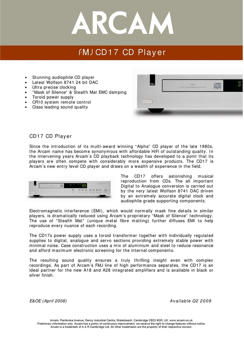
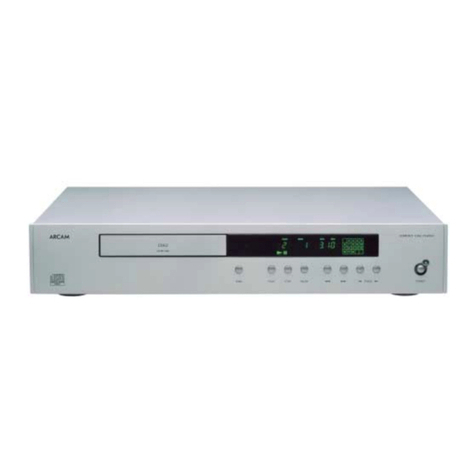
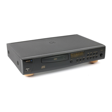
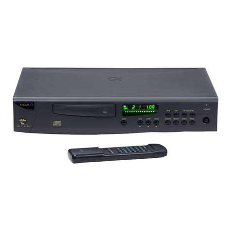
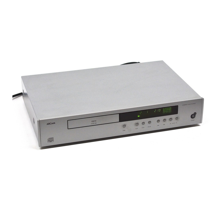
Arcam DiVA CD73 User manual

DiVA Service
Manual
CD73 Compact Disc player
Issue 1.0
ARCAM
ARCAM
Bringing music & movies to life

Diva CD73 Circuit description.
By Andy Moore.
Overview
The CD73 is a completely new design platform
for Arcam although the circuit building blocks will
show a passing resemblance to the earlier Diva
designs; the main difference is that the
mechanism control circuitry is now incorporated
within the main circuit board design of the CD
player.
Power supply and Power supply control.
The mains power supply enters the player via the
IEC socket at location SK501 and is filtered by Y
Caps C501 – C502 and X Cap C503, resistor
R501 sits between the Neutral and Positive a.c
supply rails. L501 and L502 filter electromagnetic
noise and reduce stray E.M.F.
SW501 A/B is used to switch the primary feed to
the transformer at location TX501, capacitors
C504 and C505 help to prolong the life expectancy
of the mains switch by reducing contact sparks.
The transformer at location TX501 has multiple
windings and allows for operation from 115v or a
230v mains supply, the mains select switch at
location SW502 connects the duel primaries in
series or parallel depending on the supply
requirements. For 100v operation remove J504
and J503 and fit J502 and J501.
Please note: The Primary of the transformer is
internally fused at 117 degrees C.
Fig 1. Power supply identification and related
components.
Power supply
name
Associated components
AC1 – AC2 On/Off mute circuit.
+11V(U) D.C DAC card Option at SK203.
+8V D.C U102 (tray control) U202 (laser optic –
spindle motor). Relay RLY501
analogue supply switch.
-30VF Filament display grid.
F1 – F2 Filament A.C supply.
+12V(A) Audio output op-amps U403, U404,
U405 and DAC card option at SK203.
- 12V(A) Audio output op-amps U403, U404,
U405 and DAC card option at SK203.
+5V(A)=(DAC) DAC at location U401 and DAC card
option at location SK203.
+5V(D) Digital control devices U101, U301,
U402, U406, U407, U701 and DAC card
option at SK203.
+3.6V(D) DSP at location U201, Focus/Tracking
and sledge control at location U101.
We will now breakdown the power supplies down
individually, please refer to Fig 1 for information
on key components driven by the individual
power supply section.
Digital Power supplies
AC1 – AC2 are used to drive the Audio mute
and fast power down control of the Audio output
relay at location RLY 401, Diodes D518 and
D519 rectify the A.C and the following R – C
network and transistor switch stage Q501 – Q505
allowing for the delayed switch on (+ 4 secs) and
instant power down of the Audio output relay the
control line is seen as RLYPWR on the circuit
diagram and should measure +10v D.C at
Jumper PL402.
The +11V(U) supply rail is protected by fuse
FS501 and will only be used directly when an
additional DAC card is added; we use this supply
rail within the CD73 to derive the +8V using U502
and reservoir capacitor C513, the +8V supply
feeds the Tray control and Laser optic drive
packages at location U102 and U202.
The -30VF D.C is derived from the regulator at
location U503 we should see -44V D.C at the
input pin of this device. The power supply forms
the VFD grid on the Display and is current limited
by resistor package R722 (47k ohms).
F1 and F2 provide a 1.5V AC to drive the
filament.
The +11v(U) rail is used to drive the +5(D) power
supply, the supply is regulated by the LM317 at
location U502 and drives the master clock circuit
built around U402 and the SPDIF circuit at
location U407 we also power IR in stage and
Display micro (U701) from this supply.
The +5V(D) rail is further regulated to provide the
+3.6V(D) rail using the LM317 at location U507;
this rail is used to power the DSP at location
U201 and the R.F processor at location U101.
Please note: U507 has been changed to a
LM1086 low dropout regulator, Arcam part
number 5D1086A.
Please note: The above power supplies remain
operational when the CD player is switched to
standby mode from remote control
Analogue power supplies – Standby control
The Analogue audio supply is under relay control and
has over-current protection on both + and – phases,
this is provided by FS503 and FS504 the output sides
of these fuses drive into bridge rectifier BR502, this
bridge rectifier package intern supplies the
unregulated +/- 18v D.C rails (these are used to
drive an optional DAC board).
The +/- 18v unregulated D.C rails are regulated by
U504 (+) and U505 (-) and provide the +/- 12V(A)
supplies.
We use the unregulated +18v to create the clean
+5(A) supply using regulator U506, this supply is fed
to the DAC card option socket at location SK203 but
within the CD73 this supply becomes known as the
+5(DAC) on the audio stage circuit diagram and is
used to power the DAC chip only.
The Relay at location RLY501 switches the low
voltage A.C from the secondary to the bridge rectifier
at location BR502 we will also see that relay RLY502
switches the F1 and F2 rails to the display filament,
both if these relays are switched on/off by the control
line seen as STANDBY on the circuit diagrams.
When in the on state we should see -4.8V D.C with
respect to DGND on the Base of Q309.
Clock generation.
The clock circuit is based around the 16.9344MHz
crystal at location X401 the clock from the crystal is
amplified by transistor Q403 before being dived into
two separate clock streams by the 74HCUO4 buffer
at location U402a/b/c/d, the output of U402cis fed to
the DAC (U401) and the output of U402dforms the
master clock for the DSP at location U201.
The third clock within the circuit (4MHz) can be found
at location X701A and is used to drive the Display –
Control – Keyboard scan chip U701.
Fig 2. Laser diode direct monitor points
Mechanism and Micro engine.
Three chips have direct control over the
Mechanism their locations and primary functions
follow.
U201 CXD3017Q DSP
o 16k onboard RAM error correction
o Sub Q error data error detection
o CPU interface – U701 display board
o CD text demodulator
o Auto gain for Servo loop
o Focus bias adjustment
o CPU interface
o Direct interface to DAC
U101 CXA2581N
o RF AC-DC summing
o Focus error amplifier
o Tracking error amplifier
o Centre error amplifier
U202 BA6392FP
o 4 channel BTL driver
o Direct turntable motor control (CH 4)
o Focus coil drive +/- (CH2)
o Focus coil drive +/- (CH3)
o Laser sledge drive (CH1)
We can simplify the circuit if we look at the signal
path from the Laser optic this can be seen as
laser optic output amplifier U101 – DSP control
micro U201 – Laser tracking, Focus, Spindle,
Sled control BTL U202.
The CXA2581N at location U101 is fed 6 lines of
R.F output from the laser optic these can be seen
as inputs A – F on pins 6 – 11, the inputs on pins
10 and 11 are labelled Eand Fthese are used
the internal tracking error summing this signal is
then seen as a VC output on pin 27.
We can directly monitor the R.F output from the
Laser Photo diodes at location shown in Fig 2.
These can be seen as the focus outputs on
resistors R103 and R104 these appear above the
letters eand f on the diagram, between the two
resistors the Laser diode outputs can be seen on
the solder feed thru points labelled as a, b, c, d.

The laser current can be measured a voltage drop
across R101 this should directly relate to the Laser
current as set by Sony and printed label on the side
of the optical block, this will be seen as-
KS213C
18x21
dS489
The line of text at the bottom of the label that reads
dS489 indicates that this laser optic was set to
48.9mV and will read as a measurement across
R101 as 489mV +/- 5% (the tolerance of R101 itself).
We can observe the operation of the Focus control
circuit on Pin 16 of M102 (FCS), with no disc loaded,
open and close the tray the player will now search for
a disc, at this time we should se a 170 kHz saw tooth
that saw tooth should transverse through the 0V
DIGGND as the Focus coils moves the Laser lens up
and down.
The R.F going in on pins 6 – 9 feed the internal R.F
summing amplifier, we can then see the combined
R.F output as RFDC on jumper link R222. The
signal at this point should look very similar to the
diagram in Fig 3 when the scope is set to .2uS/Div
we should see roughly 400mV pk-pk.
Fig 3. H.F eye pattern
Please note: The R.F output will obviously differ from
disc to disc use the Phillips SBC 444 playability disc if
possible.
We can see the FE error output signal on R107, this
will appear as a high frequency R.F stream of 200mV
pk-pk any excessive bounce or noise on the R.F may
indicate a damaged or worn/borderline optic. The
focus is correct when (A+D) – (B+C)= 0
The tracking error (TE) signal can be seen as a high
frequency R.F stream on R218 we should expect to
see 150-200mV pk-pk, under tracking error
conditions the R.F will rise up 300-600mV pk-pk
dependent on the severity of the error. The tracking
error is derived as E - F = 0 when correct.
The RFDC, RFAC, EF, TE, SE are now fed into
U201.
The CXD3017Q micro at location U201 performs
the majority of the Data processing and control
tasks within the CD player, the micro receives the
RFDC, RFAC for processing along with the EF,
TE, SE flags these signals are fed into the micros
A/D converter and into the Servo DSP and the
PWM modulator from this point the mechanism
control signals leave the micro and travel to the
BTL driver at location U202 as SFDR, SRDR,
TFDR, TRDR, SFDR, SFD PWM lines, the
turntable motor control line leaves the micro as
MDP and is filtered and referenced to VC to form
a single SPDR line.
The presence of the +3.6V(D) power supply is
crucial to the operation of the micro’s internal
PLL.
The micro initiates a programmed Disc load
procedure when the Disc tray is operated i.e. the
tray is closed. Do not look directly into the
beam.
o Tray Close
o Spin turntable motor
o Light laser
o Attempt focal alignment
o Read TOC
o If the player fails to read the disc check.
o Movement of Laser lenses.
o +5V (D) supply.
o +3.6V (D) supply.
o +8V supply.
o Operation of the tray micro switches.
o Laser current.
o Focus control.
The micro contains a CPU interface; this port
sends and receives Data packages from the front
panel CPU at location U701.
The active communication ports can be seen as
inputs from the CPU on DATA, XLAT, CLOK,
SYSM and XRST the output ports are SQSO (CD
text), SENS and SCOR. We should see active
data streams on SENS, DATA and SQCK and all
times when a disc is playing.

The CPU is located at component position U701 and
can be found on the front panel display board, the
CPU contains a Keyboard scan this is driven from
the resistive array powered by the VREF output at
Pin 98 the voltage drop sensed can be seen on Pin
97 (AVSS) and as 4.9 V on R701.
The CPU also receives and decodes the IR from
both the display board remote receiver and the rear
panel remote input 3.5mm jack.
Please note: The IR from the from the display panel
pickup device is not driven directly into the CPU it
takes a path onto the main board and into the IR
micro circuit the signal is mixed into the rear panel
sourced IR signal by the circuit based around Q301,
Q302, Q303 the result is a signal called RMIN this
signal is fed back to the display board and into Pin 32
of the CPU.
IR RC5 electrical signals driven into the rear panel
3.5 mm jack passed thru the Opto-isolator package at
location OP301 the signal is then clamped to 3v9 by
Zener diode D301 before reaching R-C filter network
provided by C340, C341 and R304 final drive is
supplied by U301(a) and U301(b).
Digital to Analogue conversion
The BCK, PCMD and LRCK lines from the DSP are
buffered by U406 (74HCU04) before arriving at the
D to A converter at location U401 (WM8740) these
lines are now labelled as BCLK,ADATA and
LRCKIN (left, right clock in).
The WMA740 DAC is driven from its own 5 Volt
supply, this can be seen on pin 8 as DVDD.
The de-emphasis flag arrives from the DSP on pin
number 27 (high = on)
The master audio clock arrives at pin 5 labelled at
DACLK and is supplied by the previously mentioned
circuit built around U402 (see page 2)
The Audio outputs from the DAC can be seen via
an x10 probe on R416 and R414 Left channel and
R415 and R417 Right channel, these are differential
outputs and as such will have +/- offset respectively.
The differential Audio outputs from the DAC are
summed by U403a and U404a before driving into the
output Op-amps U403b and U404b, D.C errors are
removed by servo Op-amps U405a and U405b
providing a D.C coupled output.
Optional DAC stage notes
As previously mention the main board has been
designed to provide a platform for other players
within the Diva range and as such provisions
have been made for the addition of optional D to
A stages; these can be connected to the flexi foil
sockets at locations SK203 and SK301 see Fig
3a/b for relevant pin information for these
sockets.
When fitting an optional Audio stage we need to
adjust the jumper settings on the existing main
board information on jumper settings appear
within Fig 4.
Fig 3a Pin connections for SK203.
Pin Number(s) Power supply and function
1 Digital ground
2,6,7,12,13,19,20 Analogue ground
3,4,5 +11v unregulated
9,10,11 +5v Digital supply (DAC)
14,15 +5v Analogue supply
16,17,18 -12v Analogue supply
21,22,23 +12v Analogue supply
Fig 3b Pin connections for SK301.
Pin Number(s) Function
1,2,5-9,18-
20,23,26,28,30,32.
Analogue ground
17 Emphasis
21 Reset
22 Mute
25 Left/Right clock in (LRCKIN)
27 A DATA
29 B-Clock (BCLK)
Fig 4. Option jumper settings.
Location CD73 Option
PL100 Open Open
PL202 Open Short
PL203 Short Open
PL204 Open Short
PL205 Short Open
PL300 1/2 Short 1/2 Open
PL300 2/3 Open 2/3 Short
PL400 Short Open
PL401 Short Open
PL402 Short Open
PL403 Open Short

Resources
The Test disc mention in the Mechanism and micro
engine section of this manual is available from
Philips at the below address.
Philips Consumer Electronics
Co-ordination Office Optical and Magnetic Media
Systems
Building SWA-112
PO Box 80002
5600 JB Eindhoven
The Netherlands
Fax +31 40 2732113

ARCAM - CD73
!" #$
%
""&
#'
#
#
#
#
'
#(
)
#*+
+
#*)
,
#*'
*
#*
(
#*
#*
#*
#*(
#,
'
#,
)
%
+
-..
,
#,
*
#,(
(
%
/0
/1!
%
#++
'
#+)
)
#+'
+
#+
,
#+
*
#+
(
#+
#+(
#)+
#))
#)'
'
#)
)
#)
+
#)
,
#)
*
#)(
(
#'+
#')
#''
#'
#'
'
#'
)
#'
+
#'(
,
#+
*
#)
'(
#' '
# '
# '
# '
# ''
#( ')
#+ '+
#) ',
#' '*
# )(
# )
# )
# )
#( )
2 )'
2 ))
2 )+
2( ),
2* )*
2, +(
2+ +
2) +
2' +
2 +
2 +'
2 +)
2 ++
2( +,
2* +*
2, ,(
2+ ,
2) ,
2' ,
2 ,
2 ,'
2 ,)
2 ,+
2( ,,
%.. ,*
#) *(
#' *
# *
# *
# *
# *'
#( *)
% *+
%-.2 *,
#+ **
#) ((
!+(
,+*
2
2
3
3
'
3
)
3
+
(3
,
*3
*
,3
(
+3
)3
'3
3
3
'
3
)
3
+
,
#
*
#
(
#
#
#'
#)
#+
'
#,
)
#*
+
#(
,
#
*
#
(
#
#
#'
#)
#+
'
#,
)
#*
+
#(
,
#
*
(
2
2
+(
+%2
/+(
45
+(
("2
6+(
1#.
-+(
),(-
-+(
7
-+(
7'
-+('
7
-+()
7
-+(+
)7,
-+(,
(7
6+(
#8
6+(
1#
6+(
#!.
6+('
2-
6+()
22
6+(+
#-.%
6+(,
./
-+(*
(-
-+( )7,
+(
(2
/
97
91
17
-..
7
.
1-
-0
1
!
01
0:6
-6
:-
:/
8
!.
;'%<=
>(%2
3
%
+(
0-
;'%<= -+(
(
+('
+2:(%
-+
7
-+ (7
;'%<=
0-0
+(
(
9+(
,('(
-+
(7
-+) ')(
.+(
8?#16.-1
-+' ')(
-++ (7
;'%<=
-030
8
3!1
-03
3
3
3
3
3
3
((@@'
((@@
(/
'
)
+
,
*
(
'
)
+
,
*
(
'
)
+
,
*
(
'
+(
'#0
;'%<=
2
2
3
0-0
8
!.
0:6
01
1
-0
1-
17
-030
8
/
17
91
7
-..
:-
<101-(=
-6
:/
!
.
>(%2
-+(
7+
-+
7+
3
3
-+*
7
-+,
7
3 3
+(
(4
+()
(
-036
-+
+7
-+
+7
-+
+7
-+
+7
-+
+7
>(%
-036
+
(:)@%
+
(
+(
("2
+( 0,
-++ 2
-+ (-(
2
/-
/-
+'
2
3
+('
3
3
+(
<2-1+(=
<1+('=

ARCAM - CD73
! "#
!$
$
%& '(
)
&&*$
+ ,-./
++0+0
+
+0+ 1
1
+++2)
+3
++2)4
5
++2+)
++2++)4
++2++)4
++2+)
)26
7+5
3
7+
+7
7
+7
+++2) 5
++'4
+++2) +
++'4
7
3
7
3
7
+7
++2)4
++2)4
7
+7
+++2)
+++2)
8),/
9),/
++2)4
8),/
5
++'4
+
+2)
+
++
5
+
-+
7"1:747
+
75
+71
7
+71
+++2+)
)
;
)
%+
)
;
)
%+
)
;
)
%+
)
;
)
%+
7+
3
7+ +7
8)8),%/
++2)4
++2+)
)
;
)
%+
7
+7
7 +7
8),/
8),%/
++
+
++
7+
3+1
)
;
)
%+
7+
31
9+)1
<+
<+
5
5
+
5
+
"3+
,:4-472:7/
8),/
9),/
8),/
8),/
8),%/
<+
5
<+
5
<+
5
7
31
7
+31
7
+31
7
+31
7
71
7+
+71%
7
31
7
+31
++%4
+%4
++%4
5
+
7
+31
=
==
= 7.'67
7.+
' +
=
7.'67
4
"3+
>4":34
+
%?
+
%?
"6+
':647"6
"6+
':647"6
1"+
0+)
1"+
+++)
1"+ +)
+
,-./
+
,-./
+ +,-/
7+
+ ,-./
;+
1:7++)
1"+
+)
=
=
=
=
8),/
8),/
9),/
8),/
8)
9+)1
8),%/
7.+
5)74.
7.+
5)74.
"6+ ):=4"44:7
+) +)
;+
1:7++)
,/
,/
,/ ,/
,/
,/
,/
,/
,/
++2)4
++2+)
)
;
)
%+
7+
+7
7+ +7
80),/
8),/
+
++
=
80),/
8),/
++00
++0+0+
+-
7+
+
7+
+
'+
;%'47
'+
;%'47
'+
;%'47
'+ ;%'47
'+
;%'47
7.+
5)74.
7.+
5)74.
5
+2+)
+
+2+)
;+
1:7+)2+)
;+ 1:7+)2+)
7 7+26

ARCAM - CD73
!" #$
%
""&
%
%
'
(
)
*
+,
- .
/
%0
#
+1
021
023 (
+3 )
/
)#4
#
'564
6!
-
(
)
*
,
.
'
/
+
7
%
%
0+
( +' )
+'4 *
' ,
'6 .
' /
'4
%
0+-
%+ (
0+ )
% *
0+8 ,
0+4 .
68+ /
!/
9(,
5/
,((/
0/
/
0/ /2
0/ /2
0/(
2
0/)
(/2
0/*
//2
0/,
),2
0/. (2
0/ 2
0 2*
0 (2
0(2
0
(2
0( 2,
0) 2
0* 2
0, /2
0. (2
/
/:
/
/:
/
/:
/(
//;/%
/)
//;/%
/*
//;/%
/,
//;/%
/.
//;/%
/
///;/%
+'
'
' '
'
+'
0+
07
0+
+3
023
021
+1
+3
+1
021
023
0+
0+
07
#/
5/
,/(/
;9
;9
(
/
(#4
8
!
0<3
0<1
4;7
48
4;7
48
8;#8!
/
#
.
%
,
%
*
8!
)
4
(
4
#
8;#4
-
!/
)
//
/
/
//
//!' /
%*//7
1,%
1:)%
%
/
/!=
5/
,((/
0/
)2,
;0
/
/!=
;0
-
-
-
-
-
//::
//::(
/9
>8'=4?
>8'=4?
0
2*
0
2*
8#48
#//
@!#'0
-
>#$"$A"?
1(%>?
1(%>?
0, 2*
0* 2*
1(%>?

ARCAM - CD73
!" #$
%
""&
'
(
)*
))
+) ,
%)-+* .
%)-+/ 0
1 2
+)) 3
++) 4
)*
+'
+(
1
!-
, )5'
. )5(
0 )*
2 +)
3 ))
4 %
%
%*
#)
%*
, #(
. #'
0 1
2
1 3
1
4
!4
.3+#
6/
65
7)
8
,
7 .
/5 0
- 2
5 3
% 4
5
#/
#/
7/
9+5 ,
7!1+ .
7#5 0
1+ 2
#/ 3
/) 4
/!
*))
+
+/5
/5
,
#
.
#
0
+)
2
))
3
+)
4
))
++)
+))
%
-
,
-
.
7
0
%
2
+-
3
-
4
-
-
)+
*/
%4
,
*1-
.
%4
0
8/
2
8*
3
*
,4
)+
,
%
,
%
,
+*/
,
+**
,,
#/
,.
%
,0
%
,2
%
,3
/!
.4
)5 .
#* .
5 .
-#: .
7% .,
7* ..
7/ .0
7% .2
% .3
/! 04
* 0
/! 0
% 0
% 0
/! 0,
* 0.
/! 00
% 02
)! 03
! 24
!4
7406
)450
)45
)45
)45
)4,
5
)4.5
)405
)435
)45
)5
) 445
) 45
) 25
),
)0
)0
5
)2,5
)3,5
)4445
)
;!#-)
) 5
) 45
), 445
).
)0
44
)2
5
)3
5
)4
45
40 4<
42
4<
43
,44"
4
4<
0"
0"
04"
,
04"
4<
7
8
7)
65
6/
=6/
=65
=7)
=8
=
=7
=/5
=-
=5
=/)
=6/
=65
=7)
=8
=
=7
=/5
=-
=5
=/)
'%.>?
4
4"
4
4"
4
4<4
4
4"
4,
4"
4.
4"
/5
-
5
/)
/5
-
5
/)
+)
+)
))
))
+)
+)
))
))
++)
++)
+))
+))
#)
#)
%
3
04!=.%
#
7)
-
-
+-
+-
-
-
0
4<
.
4<4
3
4<0
2
44"
4;
)+
)+
4
4<0
,44"
4<
74
.<3:@
,
4#+
4#+
-#:
5
#
)5
7
8
65
6/
)+
)+
,
.
4,
.#*
+(
+'
)5(
)5'
.
4<=,4%
+(
+'
)5(
)5'
-#:
5
#
)5
0
4<
4
-!1
5/
*1/#
'2%
%
'<.%>?
'<.%>?
'<.%>?
5/
1
1
1
1
1
1
1
1
1
1
1
'<.%>?
'<.%>?
>/-:*?

ARCAM - CD73
! "#
!$
$
%& '(
)
&&*$
+,-
,
./
0123
/'''
+
,4
+ ,4
/'''
+
,4 +
,4
+/
,4
+
//,4
''
1
/'5
//'
/'''
+/
+4
+
/4
/
/%"--
+/
/+4
/
/%"--
//'5
%/
6
%/
6
+
,/4
+
,14
/
/+
)
)7%
)7%'
)-
8
)
95+7
+"
"-:7
75
%5
;/
;
;"+-
-
,-
75.
",
-442:
8
)
)+
8+
)-+
)7%+'
)7%+
8
1
/
1
/
%/
:/
/
//'5
/1
//'5
//'5
<)=>
<)=)>
//'5
/%"--
8
/%"--
//'5
//'5
/%"--
<)=>
<)=>
+
/,4
/
5'2
/'''
+
,4
+
,4
1
/'''
+/
,4
%/
/'
+
/+4
?)=> ?)=>
+@/
'
/'''
+1
,4
+ ,4
/'''
+
,4 +1
,4
+
,4
+
//,4
''
/
/'5
//'
/'''
+
+4
+
/4
%/
6
%/
6
+1
,/4
+
,14
/'''
+
,4
+
,4
/
/'''
+
,4
%/
/'
+
/+4
?)=> ?)=> +@/
'
/ /+
<)=>
//'5
1
//'5 /
/%"--
/
%/
6
%/
6
%/
/'
?)=>
<)=>
/
//'5
/
//'5
/
//'5
/
//'5
/
//'5
/
//'5
%/
2%/
%/
2%/
%/
2%/
1
%/
2%/
/
%/5
2%/
%/4
2%/
%/8
2%/
+/1
/+4
+/ /4
+/ 4
+
/+4
+
/+4
+
/+4
A/
+/
,4
+/
,/4
+/
,4
'
1
//'
/
//'
/
//
/
/'
/'
/
/+
%57"
/
<)=>
23
,
/
2.
/
/+
+/
/,4
+/
/4
+/
/,4
//
//
/
%5
<)=>
+5"5
,
%/
2%/
%/ 2%/
%/ 2%/
1
%/ 2%/
/
%/5 2%/
%/4 2%/
%/8
2%/
+
/+4
+
/+4
+
/+4
+
/+4
+
/+4
+
/+4
+
/+4
/'5
/
%57"
-;'
8
)
/
7'-7%'%
<)=>
<)=>
-87'
/
-8-7%
+
+
/
+/
/+
//&
)
8
)
/
""12
/,
6/
;/)
///&
8
8
8
8
8
8
8
8
8
8
8
8
=7/>
/
/
+
/
+
/
/
/''7
/''7
///)
/''7
/''7
5
58
8
%5
A/
A/
+ ,
<)
/
A/
"4
A/
"4
A/1
"4
A/
"4
+
,
+
+4
+ +4
+
,
+
,
+
,
+1
,
?)=>
<)=> <)=>
'/
6%'5+
=BC&>
'//
6%'5+
=7(BC&>
=((D>
=((D"'>
4

ARCAM - CD73
!" #$
%
""&
'
(
)
*
+
,
'
(
)
*
+
,
'
(
)
*
+
,
-,
#.
'
(
)
*
+
,
'
(
)
*
+
,
'
(
)
*
+
,
'
,
'#.
!,(
)/!,
!,(
)/!,
'(
!,(
)/!,
+*
!,(
)/!,
,
!,(0
)/!,
!,(1
)/!,
)
!,(2
)/!,
3'+ ,31
3( ,31
3( ,31
3( ,31
3(, ,31
3'* ,31
!0
300
0#/
4'%56
1 1
2
2
',#
3,(
-
3,+
-
3,*
),-
3,'
,-
4'%56
4'%56
(+
,,
-
#
3-
-
3-.
.3.
7
!0
.89
.:
:
3.
:3
:-
3.2.
7
;
:-
<:
-
,
!,
+).
(
,,
3,
-
3
-
'
(
)
!,
+).
3, (*,-
*
,
',#
3(
-
3,
-
3
-*
3,
),3
,,
3,
),-
3*
,3,
+
,,#
,
,3
,
%+
3+
,3,
,
,,
,,
3.
300
3.2.
3)
-
3( ,-
<,+
*,',
<,
*,',
,)
.*
4*%
<
*,',
,*
.*
3' ,-
37',
+%307
37',
+%307
4'%56
7
83
2 2
3.2.
5:-07:3),6
!0
39
8;
!
0
=,%1
)/>
:-
#,,
?!#03
5$$@$A"6
51$ $6
51+#6
5#6
3
-
2
3.29
3,
,-
4'%
,
3.29
4'%56
(
*
(*,"
<,
0
3,)
-)
4'%56
1
1
+
,,
4'%56
1
1
<,
'+
3
,-
3
,-
<,
'+
3'
,-
3
,-
,*
,
.3.
1
3+
,3,
3
-
1
3*
,3,
1 1 1
/?=,'=,+
;3
'
(
)
*
:#:,
('
3
-
#,
?!#03
51*6
.3.#!

Other manuals for DiVA CD73
2
Table of contents
Other Arcam CD Player manuals

Arcam
Arcam CD37 User manual

Arcam
Arcam Delta 70.2 User manual

Arcam
Arcam CDS27 User manual

Arcam
Arcam Alpha cd player User manual

Arcam
Arcam DiVA CD72 User manual

Arcam
Arcam CD36 User manual

Arcam
Arcam DiVA CD73 User manual

Arcam
Arcam Alpha 9 User manual

Arcam
Arcam DiVA CD73 User manual

Arcam
Arcam FMJ CD17 User manual