Arcam ST60 User manual

SERVICE MANUAL
NETWORK STREAMER
ST60
ISSUE A

EN-2
Revision History
Issue A - Initial release

EN
EN-3
Contents
Safety Summary EN-4
Safety Guidelines EN-5
Electrostatic Discharge (ESD) Precautions EN-7
General Information EN-8
ST60 Specications EN-9
Functional Verication and Test Procedure EN-10
Troubleshooting EN-11
Theory of Operation EN-12
PSU PCB - L303 EN-12
Digital PCB - L279 EN-12
DAC PCB - L301 EN-12
Display PCB - L302 EN-12
These service instructions are only intended for use by
qualied personnel. Do not perform any servicing other than
that contained in these instructions unless qualied to do so.
Refer to the Safety Guidelines prior to performing any service
Block Diagram EN-13
L279 Main PCB Issue 2 EN-14
L301 DAC PCB Issue 2 EN-25
L302 Display PCB Issue 3 EN-32
L303 PSU PCB Issue 1 EN-36
Overall Dimensions EN-40
Exploded Drawings EN-42

EN-4
Safety Summary
The following general safety precautions must be observed during all phases of operation, service, and repair of this unit. Failure to comply with these precautions or with specic warnings elsewhere in these instructions violates
manufacturer safety standards and intended use of this unit. Harman Luxury Audio Group assumes no liability for failure to comply with these requirements.
DO NOT OPERATE IN AN EXPLOSIVE ATMOSPHERE
Do not operate the unit in the presence of ammable gasses or fumes. Operation of any electrical instrument in such an environment constitutes a denite safety hazard.
KEEP AWAY FROM LIVE CIRCUITS
Operating personnel must not remove unit covers. Qualied maintenance personnel must make component replacements and internal adjustments. To avoid personal injuries, always disconnect power and discharge circuits before
touching them.
DO NOT SERVICE OR ADJUST ALONE
Do not attempt internal service or adjustment unless another person capable of rendering rst-aid resuscitation is present.
DO NOT SUBSTITUTE PARTS OR MODIFY INSTRUMENT
Because of the danger of introducing additional hazards, do not install substitute parts or perform any unauthorized modication to the unit.
DANGEROUS PROCEDURE WARNINGS
Warnings such as the example shown below precede potentially dangerous procedures throughout this document. Instructions contained in warnings must be followed.
WARNING
Dangerous voltages capable of causing death are present in this unit. Use extreme caution when handling, testing, or adjusting.
EN-5
Safety Guidelines
Read these instructions.
Keep these instructions.
Heed all warnings.
Follow all instructions.
Do not use this apparatus near water.
Clean only with dry cloth.
Do not block any ventilation openings. Install in
accordance with the manufacturer’s instructions.
Do not install near any heat sources such as radiators,
heat registers, stoves, or other apparatus (including
ampliers) that produce heat.
Do not defeat the safety purpose of the polarized or
grounding-type plug.
A polarized plug has two blades with one wider than
the other. A grounding type plug has two blades and
a third grounding prong. The wide blade or the third
prong are provided for your safety. If the provided plug
does not t into your outlet, consult an electrician for
replacement of the obsolete outlet.
Protect the power cord from being walked on or
pinched particularly at plugs, convenience receptacles,
and the point where they exit from the apparatus.
Only use attachments/accessories specied by the
manufacturer.
Use only with the cart, stand, tripod, bracket, or
table specied by the manufacturer, or sold with the
apparatus.
When a cart is used, use caution when moving the cart/
apparatus combination to avoid injury
from tip-over.
Unplug this apparatus during lightning
storms or when unused for long periods
of time.
Refer all servicing to qualied service personnel.
Servicing is required when the apparatus has been
damaged in any way, such as power-supply cord or
plug is damaged, liquid has been spilled or objects
have fallen into the apparatus, the apparatus has been
exposed to rain or moisture, does not operate normally,
or has been dropped.
Object or liquid entry
WARNING – Take care that objects do not fall and liquids
are not spilled into the enclosure through any openings.
The equipment shall not be exposed to dripping or
splashing. Liquid-lled objects such as vases should not
be placed on the equipment.
Climate
The equipment has been designed for use in moderate
climates and in domestic situations.
Cleaning
Unplug the unit from the mains supply before cleaning.
The case should normally only require a wipe with a
soft, lint-free cloth. Do not use chemical solvents for
cleaning.
We do not advise the use of furniture cleaning sprays
or polishes as they can cause permanent white marks.
Power sources
Only connect the equipment to a power supply of
the type described in the operating instructions or as
marked on the equipment.
The primary method of isolating the equipment from
the mains supply is to remove the mains plug. The
equipment must be installed in a manner that makes
disconnection possible.
Abnormal smell
If an abnormal smell or smoke is detected from the
equipment, turn the power o immediately and unplug
the equipment from the wall outlet. Contact your dealer
and do not reconnect the equipment.
Damage requiring service
The equipment should be serviced by qualied service
personnel when:
The power-supply cord or the plug has been damaged,
or
Objects have fallen, or liquid has spilled into the
equipment, or
The equipment has been exposed to rain, or
The equipment does not appear to operate normally or
exhibits a marked change in performance, or
The equipment has been dropped or the enclosure
damaged.
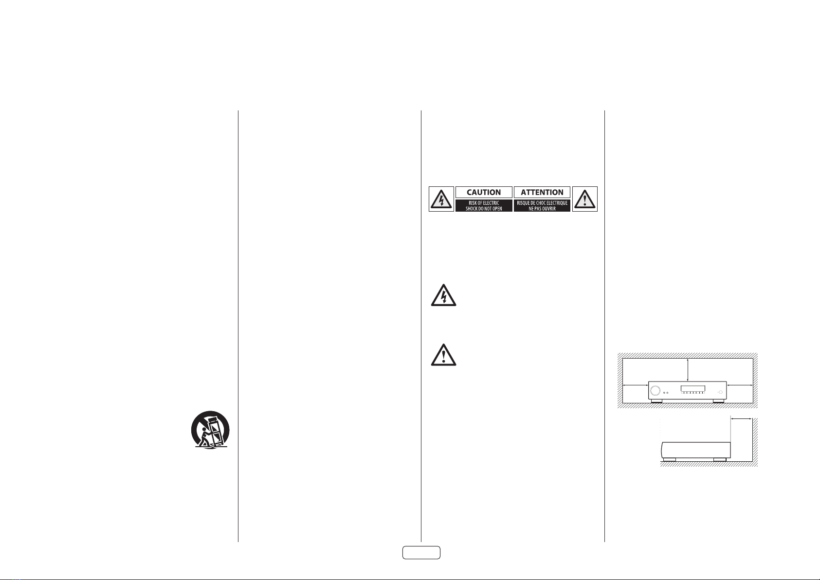
CAUTION: To reduce the risk of electric shock, do
not remove cover (or back). No user serviceable
parts inside. Refer servicing to qualied service
personnel.
WARNING: To reduce the risk of re or electric shock,
do not expose this apparatus to rain or moisture.
The lightning ash with an arrowhead
symbol within an equilateral triangle, is
intended to alert the user to the presence of
uninsulated ‘dangerous voltage’ within the
product’s enclosure that may be of sucient magnitude
to constitute a risk of electric shock to persons.
The exclamation point within an equilateral
triangle is intended to alert the user to the
presence of important operating and
maintenance (servicing) instructions in the
literature accompanying the product.
CAUTION: In Canada and the USA, to prevent
electric shock, match the wide blade of the plug to
the wide slot in the socket and insert the plug fully
into the socket.
Class II product
This equipment is a Class II or double insulated electrical
appliance. It has been designed in such a way that it
does not require a safety connection to electrical earth
(“ground” in the U.S.)
Warning
Mains plug/appliance coupler is used to disconnect
device and it shall remain readily operable.
Safety Compliance
This equipment has been designed to meet the IEC/EN
62368-1 international electrical safety standard.
This device complies with Part 15 of the FCC Rules.
Operation is subject to the following two conditions:
This device may not cause harmful interference, and
This device must accept any interference received,
including interference that may cause undesired
operation.
The building installation shall be regarded as providing
protection in accordance with the rating of the wall
socket outlet.
Caution on installation
For proper heat dispersal, do not install this unit in a
conned space, such as a bookcase or similar enclosure.
More than 0.3m (12in) is recommended.
Do not place any other equipment on this unit.
zz
z
Wall
z

EN-6
FCC Information(for US customers)
This product complies with Part 15 of the FCC Rules.
Operation is subject to the following two conditions:
This device may not cause harmful interference, and
This device must accept any interference received,
including interference that may cause undesired
operation.
IMPORTANT NOTICE: DO NOT MODIFY THIS
PRODUCT
This product, when installed as indicated in the
instructions contained in this manual, meets FCC
requirements. Modication not expressly approved by
ARCAM may void your authority, granted by the FCC, to
use the product.
NOTE
This product has been tested and found to comply with
the limits for a Class B digital device, pursuant to Part 15
of the FCC Rules. These limits are designed to provide
reasonable protection against harmful interference in a
residential installation.
This product generates, uses and can radiate radio
frequency energy and, if not installed and used in
accordance with the instructions, may cause harmful
interference to radio communications. However, there
is no guarantee that interference will not occur in a
particular installation. If this product does cause harmful
interference to radio or television reception, which can
be determined by turning the product OFF and ON, the
user is encouraged to try to correct the interference by
one or more of the following measures:
Reorient or relocate the receiving antenna.
Increase the separation between the equipment and
receiver.
Connect the product into an outlet on a circuit dierent
from that to which the receiver is connected.
Consult the local retailer authorized to distribute this
type of product or an experienced radio/TV technician
for help
Safety Information (for European customers)
Avoid high temperatures. Allow for sucient heat
dispersion when installed in a rack.
Handle the power cord carefully. Hold the plug when
unplugging the cord.
Keep the unit free from moisture, water, and dust.
Unplug the power cord when not using the unit for
long periods of time.
Do not obstruct the ventilation holes.
Do not let foreign objects into the unit.
Do not let insecticides, benzene, and thinner come in
contact with the unit.
Never disassemble or modify the unit in any way.
Ventilation should not be impeded by covering the
ventilation openings with items, such as newspapers,
tablecloths or curtains.
Naked ame sources such as lighted candles should not
be placed on the unit.
Observe and follow local regulations regarding battery
disposal.
Do not expose the unit to dripping or splashing uids.
Do not place objects lled with liquids, such as vases,
on the unit.
Do not handle the mains cord with wet hands.
When the switch is in the OFF position, the equipment
is not completely switched o from MAINS.
The equipment shall be installed near the power supply
so that the power supply is easily accessible.
A note about recycling
This product’s packaging materials are recyclable
and can be reused. Please dispose of any materials in
accordance with the local recycling regulations.
When discarding the unit, comply with local rules or
regulations.
Batteries should never be thrown away or incinerated
but disposed of in accordance with the local regulations
concerning battery disposal.
This product and the supplied accessories, excluding
the batteries, constitute the applicable product
according to the WEEE directive
Correct disposal of this product
These markings indicate that this product should not be
disposed with other household waste throughout the
EU.
To prevent possible harm to the environment or
human health from uncontrolled waste disposal and
to conserve material resources, this product should be
recycled responsibly.
To dispose of your product, please use your local return
and collection systems or contact the retailer where the
product was purchased.
Pb

EN-7EN-7
Keep circuit boards in their original packing until ready for use.
Avoid having plastic, vinyl or styrofoam in the working area.
Wear an anti-static wrist strap.
Discharge personal static before handling circuit boards.
Remove and insert circuit boards with care
When removing circuit boards, handle only by non-conductive surfaces. Never touch open-edge
connectors except at a static fre work station.
Minimize handling of circuit boards.
Handle each circuit board by its edges.
Do not slide circuit boards over any surface.
Insert circuit boards with the proper orientation.
Use static shielded containers for storing and trasporting circuit boards
Electrostatic Discharge (ESD) Precautions

EN-8
The ARCAM brand has become synonymous with the cinema experience. The ST60 Streamer continues this legacy.
The ST60 is a high-performance streaming source that enables streaming audio from all of the major services (Tidal, Qobuz, Spotify, Napster, Deezer, etc) over Cast or Airplay2. It will also handle UPnP sources and is Roon Ready.
It is the perfect companion for the HDA range of stereo ampliers and is also fully compatible with the MusicLife app.
HIGHLIGHTS
• 4 digital inputs
• Balanced XLR and Single ended RCA analogue outputs
• Optical and coaxial digital outputs
• GoogleCast, Airplay2, uPnP Streamer
• Roon endpoint
• MQA supported
• 32-bit ESS9038K2M Sabre DAC
• Full I/P and RS232 control including Control4 and Crestron
• Total harmonic distortion + noise = 0.0008%
ROUTINE MAINTENANCE
There is routine maintenance that should performed on a periodic basis to prevent the unit from degrading in performance and cosmetic condition. Clean the exterior with a soft, lint-free cloth. Do not use alcohol, benzene, acetone-
based cleaners, or strong commercial cleaners. If the unit is exposed to a dusty environment, you can use a vacuum with a brush attachment to suck all dust and debris from the unit. Even a low pressure air compressor can be used to
remove dust from its exterior surface. Any cleaning or dusting should be done externally, preventatively.
General Information

EN-9
ST60 Specications
Analogue Outputs
Digital to Analogue Conversion ESS9038 32-bit/192kHz Delta-Sigma DAC
Signal/Noise Ratio (Awtd) 118dB unbalanced, 122db balanced
Harmonic Distortion (1kHz) <0.0008%
Frequency response 10Hz – 20kHz ± 0.5dB
Output Level (Fixed) 2.2Vrms unbalanced, 4.5Vrms balanced
Output Impedance 47Ω unbalanced, 600Ω balanced
Minimum Recommended Load 5kΩ
RMS Jitter < 20 psec
Digital Inputs
SPDIF Receiver AKM4113
Supported sample rates Optical 32kHz, 44.1kHz, 48kHz, 88.2kHz, 96kHz
Coaxial 32kHz, 44.1kHz, 48kHz, 88.2kHz, 96kHz, 176.4kHz, 192kHz
Bit depth 16-bit – 32-bit
Digital Interfaces
USB USB 2.0 High Speed (480Mbps)
Ethernet 10/100Mbps
Wireless 802.11b/g/n
General
Mains voltage 110–240V, 50–60Hz
Maximum power consumption 10W
Low power standby consumption 0.5W
Network standby consumption 2W
Dimensions W x H x D (including feet and control
knob)
433x102x306mm
Weight (net) 5.5kg
Weight (gross) 7.9kg
Supplied accessories Mains leads
Remote control
2 x AAA batteries
User Manual
2 x WiFi Antenna

EN-10
Functional Verication and Test Procedure
Digital inputs and RCA output level check
Check each digital input gives 2.1V at the RCA output with a 0dFS 1kHz tone input.
XLR output level check
Using one of the digital inputs check XLR output level is 4.2V with a 0dFS 1kHztone input.
THD+N RCA outputs
Using one of the digital inputs check THD+N is 0.001% at the RCA output terminals with a 0dFS 1kHz tone input.
Frequency Response RCA outputs
Using a xdBFS 20-22kHz sweep tone applied to one digital input check output level at RCAs.
The output level should stay between -0.5dB and +0.2dB from 20-20kHz with respect to 2.1V reference level.
Mute Check
• Apply a signal to one of the digital inputs.
• Check there is an output signal on RCA, XLR and digital outputs.
• Mute the unit using remote control and check the output signal disappears.
• Unmute the unit with the remote control and check that the output signal returns.
Check RS232
• Connect RS232 to unit.
• Open the ST60 console.
• In the connection tab select the correct com port and set baud rate to 38400.
• In the RS232 command tab send a mute command (make sure RS232 tick box is checked).
• Check the unit is muted, display should indicate the unit is muted or use audio outputs.
Check Ethernet
• Connect Ethernet cable to unit.
• In RS232 command tab request IP address (make sure RS232 tick box is checked) and make a note of IP
address.
• Enter IP address in connection tab.
• In RS232 command tab send an unmute command (make sure TCPIP tick box is checked not RS232).
• Check the unit is not muted, display should indicate the unit is not muted or useaudio outputs.
Check Airplay
• Connect Ethernet cable to unit.
• Play a track in iTunes and airplay to the ST60, make sure track is played back via RCA or XLR output.
• Check playback from digital output.
Check USB playback
• Plug in USB stick to ST60 with an audio test track.
• Use remote control to navigate to the USB input and play a track.
• Make sure track is played back via RCA or XLR output.
Check GoogleCast
• Remove Ethernet cable
• Setup unit up via Googlecast
Check Display
• Using engineering menu run display test. Look for dead pixels.
• To access engineering menu select Digital 1 input. Press and hold encoder for > 3s, on release the
engineering menu will be displayed.
Check front panel controls
• Check encoder works.
• Check input, play and menu button work.
EN-11EN-11
Problem Check the following
No sound The ST60 is correctly plugged in and switched on.
Your audio source is correctly connected, the correct input is selected
and it is not muted.
The unit responds erratically or not at
all to the remote control
Remote batteries are not running out.
The front panel window is visible and you are pointing the remote control
towards it.
The front panel display is blank The display hasn’t been turned o.
Dark mode is enabled.
Cannot control the volume Fixed volume mode is enabled.
Troubleshooting

EN-12
Theory of Operation
The ST60 contains three PCBs, the PSU, main digital
audio PCB, DAC PCB and the display PCB. What follows
is a detailed overview of each PCB as well as any signals
that go between the PCBs.
A note on standby modes
The ST60 has a number of dierent standby modes as
set by the Standby Settings menu.
Standby Mode Note
RS232 NET
OFF OFF Lowest power mode.
Network module disabled
no RS32 or IP control.
ON OFF Network module disabled.
RS232 control availble, no
IP control
ON ON Network module enabled.
RS232 and IP control
availble.
PSU PCB - L303
The ST60 runs on 5VDC with the other supplies being
generated loacally where required from this 5V rail.
The PSU PCBs sole purpose is to convert AC mains to 5V.
The AC live is isloated/switch by the front panel
mounted switch.
The live and neutral are connected to the XP VCE PSU
module which generates the 5VDC for the rest of the
unit.
5V and 0V is connected to the main digital PCB by a 6
way header CON2.
Digital PCB - L279
The digital PCB has 4 main components and functions:
• Host microcontroller (MCU).
• Network module.
• Digital audio output.
• Digital audio input.
Host MCU
The host MCU IC400 controls the various components
in the ST60 using dierent communications intefaces.
I2C to control the network module (MOD200).
I2C to control the DAC and SPDIF receiver (IC100).
SPI to control the SPDIF transmitter (IC102).
RS232 to control the front panel MCU.
The MCU is powered by 3.3V generated locally from the
5V rail by REG500.
Network module
The network (avatar) module is responsible for receiving
and generating the digital audio from the various
streaming services as well as from USB sticks.
The module is conencted to the network via wi or by
wired ethernet. Wi circuitry is contained within the
module itself. For wired ethernet the avatar controls an
external phy (IC204).
The audio is rendered by the avatar module in the I2S
format and is buered to the DAC and SPDIF transmitter
by IC200 and IC201.
The network module is powered via 5V which is turned
on/o by the host MCU using M500.
The I2S audio is sent to the DAC PCB via CON1
Digital Audio Output
The ST60 has both a coaxial and optical SPDIF output.
Both of which are generated by IC102.
IC102 is powered by 3.3V genetated by REG501.
NOTE: The digital and analogue audio are mutually
exclusive i.e only one type of output can be enabled
at any one time. The output type is set using the
Digital Output option in the Audio Settings Menu.
Digital Audio Input
The ST60 has a pair of coaxial and optical SPDIF inputs
all of which are received and converted to I2S via IC100.
The I2S audio is sent to the network audio module
which switches between streamed audio content and
the external SPDIF inputs.
IC100 is powered by the same 3.3V rail as the SPDIF
output.
DAC PCB - L301
The DAC (IC103) converts the I2S audio to analogue
audio which is output via the single ended RCA and
balanced XLR outputs.
The balanced outputs are fed directly from the IV stage
in the DAC lter (IC100 & IC104). These signals are
combined in the nal stage of the lter and converted
to single ended (IC102).
IC101 is used to set a mid rail DC reference level for the
analogue output.
The DAC has muliple 3.3V supplies all generated from
the main 5V rail.
The output lter runs on +/-5V. The -5V rail is generated
by a charge pump (IC201).
Display PCB - L302
The LCD display (DISP1) on the ST60 is a self contained
module that includes all the required drivers and local
power supplies.
It is powered via 5V and 3.3V. The power supplies are
generated by REG1 and M1 both of which are controlled
by the host MCU.
The display itself is controlled by a dedicated MCU
IC1. This MCU is responsible for sending data in order
draw the GUI. The information that is to be displayed
is supplied by the main host MCU via and RS232
connection.
The back light for the display is controlled by the main
host MCU with TR2.
The display MCU is powered by REG1
The front panel encoder, switches and LEDs are all
under the control of the main host MCU.

EN-13
Block Diagram
ISSUE
DRAWING NO.
DRAWING TITLE
DATE
Filename:
ECO No. DESCRIPTION OF CHANGE
ST60 Streamer Block Diagram Rev B.SchDoc
ST60 block diagram Rev B
Contact Engineer: LXXXCT
27/01/2020
INITIALS
Printed: X YSheet of
Notes:
Contact Tel: +44 (0)1223 203201Jon Henderson
A& R Cambridge Ltd.
Stirling House
Cambridge CB25 9PB
Waterbeach
A3
ARCAM
Avatar
RTL8201
RealTek PHY
RMII Ethernet
RJ45
USB type A
USB
DAC
ES9038Q2MI2C
MCU
PIC32MZ2048EFG100-I/PF
I2C
IRQ
SPI
SPI Flash
64 Mb
MCU control
Analogue
I2S
Avatar control
Front panel keys
WiFi
CoaxialOptical
SPDIF
SPDIF Receiver
AKM4113
SPDIF Transmitter
AK4104ET
Optical
Coaxial
RS232
RS232
IR Encoder
Front panel
Fixed or Variable Output
TFT Display
SPI Flash
64 Mb
PIC32MZ
RS232
PIC Control
SPI
GPIO
TFT Controller
3 WIRE
I2S MUX
NO LONGER
REQUIRED

EN-14EN-14
L279 Main PCB Issue 2
EN-15
23425
Bill of Materials
Part Description SYS009 Main PCB Assembly
Part Number L279AY
Issue 2.0.0
Report Type Fitted Parts Only
SYS009 Main PCB Assembly
Part Number Quantity Description Issue Designators
Resistor 1206 Surface Mount 0.25W 1% 4R7 R20 R211A847 2 1
Resistor 0603 Surface Mount 0.063W 0R0 R1 R10 R11 R12 R13 R14 R15 R16 R17 R18 R19 R2
R22 R274 R3 R4 R407 R5 R6 R7 R8 R9
1N000 22 1
Resistor 0603 Surface Mount 0.063W 1% 10R R4221N010 1 1
Resistor 0603 Surface Mount 0.063W 1% 68R R1041N068 1 1
Resistor 0603 Surface Mount 0.063W 1% 100R R101 R102 R116 R121 R200 R201 R202 R203 R204
R205 R206 R219 R221 R222 R227
1N110 15 1
Resistor 0603 Surface Mount 0.063W 1% 110R R1191N111 1 1
Resistor 0603 Surface Mount 0.063W 1% 220R R1171N122 1 1
Resistor 0603 Surface Mount 0.063W 1% 1K0 R2721N210 1 1
Resistor 0603 Surface Mount 0.063W 1% 2K49 R2661N2249 1 1
Resistor 0603 Surface Mount 0.063W 1% 10K R118 R120 R400 R409 R410 R411 R412 R413 R414
R415 R416 R425 R426 R429 R431 R501 R503 R504
R505 R509
1N310 20 1
Resistor 0603 Surface Mount 0.063W 1% 15K R1081N315 1 1
Resistor 0603 Surface Mount 0.063W 1% 27K R502 R5071N327 2 1
Resistor 0603 Surface Mount 0.063W 1% 47K R5111N347 1 1
Resistor 0603 Surface Mount 0.063W 1% 62K R5101N362 1 1
Resistor 0603 Surface Mount 0.063W 1% 120K R500 R5061N412 2 1
Resistor 0603 Surface Mount 0.063W 1% 910K R5081N491 1 0
Resistor 0402 Surface Mount 0 ohm jumper C107 R210 R213 R214 R215 R228 R229 R230 R2321NC000 9 1
Resistor 0402 Surface Mount 0.062W 1% 33R R100 R106 R216 R217 R218 R220 R226 R231 R233
R235 R236 R239 R240 R241 R243 R244 R255 R256
R257 R259 R265 R401 R403 R404
1NC033 24 1
Report generated on 21/08/2020 Page 2 of 6

EN-16
23425
Bill of Materials
Part Description SYS009 Main PCB Assembly
Part Number L279AY
Issue 2.0.0
Report Type Fitted Parts Only
SYS009 Main PCB Assembly
Part Number Quantity Description Issue Designators
Resistor 0402 Surface Mount 0.062W 1% 75R R103 R1091NC075 2 1
Resistor 0402 Surface Mount 0.062W 1% 100R R2111NC110 1 A
Resistor 0402 Surface Mount 0.062W 1% 470R R234 R2371NC147 2 1
Resistor 0402 Surface Mount 0.062W 1% 2K2 R260 R2611NC222 2 1
Resistor 0402 Surface Mount 0.062W 1% 4K7 R247 R248 R249 R263 R267 R268 R269 R417 R418
R419 R420
1NC247 11 1
Resistor 0402 Surface Mount 0.062W 1% 10K R107 R209 R238 R254 R264 R2701NC310 6 1
Resistor 0402 Surface Mount 0.062W 1% 1M0 R2121NC510 1 1
Capacitor SM 0402 X7R Ceramic 10% 16V 10N C116 C117 C130 C138 C144 C150 C206 C207 C224
C225 C239 C242 C246 C249 C305 C309 C317 C320
C413 C414 C415 C416 C433 C434 C436 C504 C506
C508 C515 C519 C521 C525
2FA310 32 1
Capacitor SM 0402 X7R Ceramic 10% 16V 100N C108 C110 C112 C115 C131 C132 C133 C139 C140
C141 C145 C146 C147 C151 C152 C208 C209 C210
C211 C212 C226 C227 C228 C229 C230 C244 C247
C250 C256 C265 C266 C270 C299 C300 C302 C303
C307 C311 C312 C313 C314 C315 C316 C322 C323
C401 C407 C408 C411 C412 C418 C419 C420 C421
C422 C423 C424 C425 C426 C427 C428 C429 C435
C510 C511 C512 C522 C523 C524
2FA410 69 1
Capacitor SM 0402 X5R Ceramic 10% 6.3V 1uFC240 C241 C301 C318 C3192FC510 5 1
Capacitor SM 0402 NPO Ceramic 5% 50V 15P C1 C10 C100 C101 C106 C12 C13 C14 C15 C16 C17
C18 C19 C201 C203 C215 C217 C219 C221 C233 C235
C258 C259 C261 C262 C263 C264 C267 C268 C269
C271 C272 C273 C274 C275 C276 C277 C278 C279
C280 C281 C282 C283 C284 C285 C286 C287 C288
C289 C290 C291 C292 C294 C295 C297 C3 C324 C4
C400 C402 C404 C5 C6 C7 C8 C9
2FD015 66 1
Report generated on 21/08/2020 Page 3 of 6
EN-17
23425
Bill of Materials
Part Description SYS009 Main PCB Assembly
Part Number L279AY
Issue 2.0.0
Report Type Fitted Parts Only
SYS009 Main PCB Assembly
Part Number Quantity Description Issue Designators
Capacitor SM 0402 NPO Ceramic 5% 50V 33P C109 C111 C113 C1142FD033 4 1
Capacitor SM 0402 NPO Ceramic 5% 50V 100P C255 C2602FD110 2 1
Capacitor SM 0402 X7R Ceramic 10% 50V 1nFC129 C204 C205 C222 C223 C238 C243 C245 C248
C298 C304 C308 C321
2FE210 13 1
Capacitor SM 0805 X5R Ceramic 10% 25V 10UFC257 C306 C3102JE701 3 1
Capacitor SM 0603 X5R Ceramic 10% 6.3V 10uFC137 C143 C149 C253 C254 C503 C507 C509 C514
C518 C520 C526
2JG610 12 1
Capacitor SM 0603 NPO Ceramic 5% 50V 22P C505 C5162LA022 2 1
Capacitor SM 0603 NPO Ceramic 5% 50V 27P C293 C2962LA027 2 1
Capacitor SM 0603 NPO Ceramic 5% 50V 33P C134 C409 C4102LA033 3 1
Capacitor SM 0603 NPO Ceramic 5% 50V 100P C135 C431 C4322LA110 3 1
Capacitor Low Impedance Radial Electrolytic 6.3mm Dia
5mm Pitch 100UF 16V - RoHS OK
C128 C136 C142 C148 C213 C231 C236 C237 C251
C252 C500 C501 C502 C513
2RX710D 14 1
Capacitor Low Impedance Radial Electrolytic 10mm Dia
5mm Pitch 470UF 16V - RoHS OK
C5172RX747B 1 1
Diode Dual Surface Mount Small Signal BAV99 SOT-23
Package
D1003AV99 1 1
Digital Transistor MMUN2211LT1 SOT23 Package TR500 TR5034D10KN 2 1
Transistor Mosfet FDN340P SOT-23 Package M500 M5034K340P 2 1
IC SPDIF Transmitter AK4104VF TSSOP-16 IC1025A4104 1 1
IC SPDIF Receiver AK4113VF VSOP-30 package IC1005A4113 1 1
IC DC DC Wurth 171960501 REG500 REG5015D17196 2 1
IC Voltage Regulator 1.8V TPS79318 SOT23 Package REG2015D79318 1 1
IC Voltage Regulator 3.3V TPS79333 SOT23 Package REG2005D79333 1 1
Report generated on 21/08/2020 Page 4 of 6

EN-18
23425
Bill of Materials
Part Description SYS009 Main PCB Assembly
Part Number L279AY
Issue 2.0.0
Report Type Fitted Parts Only
SYS009 Main PCB Assembly
Part Number Quantity Description Issue Designators
IC CPU Apple authentication IC Version 3.0 XDFN
Package
IC2065H05 1 A
IC Serial Flash 64Mbit SST26VF064B SO-8 IC4035H26064 1 A
IC Micro Reset MIC2774N-29YM5 SOT23-5 Package IC5005H2774 1 1
IC Microprocessor PIC32MZ2048EFG TQFP 100 package IC4005HMZ2048 1 1
IC Quad Buffer 5V Tol 74LVC125AD SMT IC200 IC2015KLVC125 2 1
IC Single Bus Buffer Gate 74LVC1G125 SOT-23 package IC103 IC208 IC401 IC4045KLVC1G125 4 1
IC ESD Protection TPD2E001DZDR SOP-4 Package IC2035N2001 1 1
IC PWR SWITCH TPS2051B SOT23 IC2025N2051BDBV 1 1
IC RS232 Charge Pump Driver MAX3232CPW IC4025N3232C 1 1
IC ESD Protection PESD5V0U1BB SOD-523 D200 D201 D202 D2035N5V01 4 1
IC Ethernet PHY RTL8201FR-VD QFR-24 IC2045N8201 1 1
SPDIF Optical RX Toslink ZK GQ 005 RX100 RX1015TZKGQ005 2 1
SPDIF Optical TX Toslink ZK-GQ-04-002 TX1025TZKGQ04 1 1
Transformer Digital Audio DA101C TX100 TX1017AD101 21.0
Common Mode Choke 2200R@100MHz L203 L2047E112 2 1
Ferrite Bead SM0603 220R@100MHz 2A L200 L201 L500 L5027F222 4 A
Ferrite Bead BLM18A SM0603 600R@100MHz 500mA L101 L102 L103 L104 L106 L202 L205 L206 L207 L208
L400
7F223 11 1
Crystal 25MHz Lihom Crystal BMC-30 X2007X098 1 1
Crystal 24.576MHz Lihom Crystal BMC-30 X1007X099 1 1
Crystal 12MHz Lihom Crystal BMC-30 X4007X100 1 1
RJ45 8WAY Connector with magnetics and USB 2.0 port CON2018B0065 1 1
Report generated on 21/08/2020 Page 5 of 6
EN-19
23425
Bill of Materials
Part Description SYS009 Main PCB Assembly
Part Number L279AY
Issue 2.0.0
Report Type Fitted Parts Only
SYS009 Main PCB Assembly
Part Number Quantity Description Issue Designators
Con Dtype Horiz 9WAY Male With Boardlock Sung Nam
Electronics
CON4038B0070 1 1
Phono Skt 2-Way Black Trenpro SKT1008B0089 1 1
Con DDR4 SODIMM Avatar CON2008B059 1 1
Phono Skt 1-Way Black Split Tianx SKT1018B066 1 1
Con Single ROW Hdr 0.1IN Vertical 3WAY CON2098K2103 1 1
Con JST VH Series Vertical 4WAY - ROHS compliant CON48K3804 1 1
Con JST VH Series Vertical 6WAY - ROHS compliant CON38K3806 1 1
Con Single ROW Hdr 0.1IN Vertical 6WAY - ROHS CON4008K6206 1 A
Con 1.00MM Vertical SM FFC 16WAY CON18K8316 1 1
Con 1.00MM Horiz SM FFC 30WAY - This part is RoHS
compliant.
CON28K8430 1 A
Switch Tact Sdt Series SW200A1501 1 A
Switch Tact SM SW201A1505 1 1
Avatar stream unlimited module MOD200B047 1 1
Blank PCB L279PB SYS009 MAIN PCB PCB1L279PB 1 2
End of Assembly -494 items
Report generated on 21/08/2020 Page 6 of 6

EN-20
ISSUE
DRAWING NO.
DRAWING TITLE
DATE
Filename:
ECO No. DESCRIPTION OF CHANGE
L279 CT1 Top Level.SchDoc
SYS009 - Main PCB Top Level
Contact Engineer: L279CT
21/08/2020
INITIALS
Printed: 1 5Sheet of
Notes:
Contact Tel: (01223) 203207Peter Kuell
A& R Cambridge Ltd.
Pembroke Avenue
Cambridge CB25 9QR
Waterbeach
A3
ARCAM
SCL SUE
EXT_LRCLK
DAC SDATA
SDA SUE
HOST IRQ
AVA TRST
EXT_MCLK
EXT_DATA
EXT_BCLK
DAC BCLK
AVA BOOTMODE
DAC LRCLK
DAC MCLK
AVATAR MUTE OUT*
SPDIF SDATA OUT
SPDIF LRCLK OUT
SPDIF BCLK OUT
SPDIF MCLK OUT
DAC EN*
AVA READY
SPDIF EN*
RS232 RX FP DBUG
RS232 TX FP DBUG
IP DET
Avatar Module
L279 CT3 Avatar Module.SchDoc
3W DATA
AVA TRST*
SCL
HOST IRQ
SPDIF INT0
SPDIF TX RES*
SDA
AVA BOOTMODE
SPDIF INT1
SDA SUE
SPDIF RES*
3W CLK
SUE PSU EN
3W 4104 CS*
SCL SUE
DAC MUTE*
DAC GPIO
DAC RES*
AN PSU EN
IP DET
HP PRESDIG PSU EN
SCAN1
ENC2 A
ENC A
ENC2 B
ENC B
SCAN2
SCAN3
STBY RED
WHITE LED
IR IN
GREEN LED
STBY KEY
ENC SW
RS232 TX FP
DISP PSU EN
MCLR FP*
RS232 RX FP
AVATAR MUTE OUT*
SPDIF EN*
DAC EN*
AVA READY
DAC PSU EN
RS232 TX FP DBUG
RS232 RX FP DBUG
RESET*
LCD PSU EN
MCU
L279 CT4 MCU.SchDoc
EXT_LRCLK
EXT_DATA
EXT_BCLK
SPDIF INT0
3W CLK
SPDIF INT1
SDA
SCL
3W 4104 CS*
EXT_MCLK
3W DATA
SPDIF RES*
SPDIF TX RES*
SPDIF MCLK OUT
SPDIF BCLK OUT
SPDIF SDATA OUT
SPDIF LRCLK OUT
SPDIF Inputs
L279 CT2 SPDIF Rx.SchDoc
SUE PSU EN
PSU EN
RESET*
PSU
L279 CT5 PSU.SchDoc
ENC A
ENC B
IR IN
STBY RED
GREEN LED
WHITE LED
SCAN1
SCAN2
SCAN3
DGND
+5V STBY
1
2
3
4
5
6
VH
CON3
JST
+5V STBY
DGND
AN PSU EN
DAC GPIO
DAC BCLK
DAC LRCLK
DAC SDATA
SCL
SDA
DAC RES*
DAC PSU EN
TO DAC PCB
1
2
3
4
5
6
7
8
9
10
11
12
13
14
15
16
52808
CON1
MOLEX
DAC MCLK
DGND
ENC2 A
ENC2 B
HP PRES
STBY KEY
DAC MUTE*
TO DISPLAY PCB
TO PSU PCB
ENC SW
1
2
3
4
5
6
7
8
9
10
11
12
13
14
15
16
17
18
19
20
21
22
23
24
25
26
27
28
29
30
52793
CON2
MOLEX
DISP PSU EN
LCD PSU EN
RS232 TX FP
RS232 RX FP
MCLR FP*
0W063
R1
0R0
R2
R3
R4
R5
R6
R7
R8
R9
R10
R11
R12
R13
R14
R15
R16
R17
R18
R19
50V
C1
15P
C11
C2
C12
C3
C13
C4
C14
C5
C15
C6
C16
C7
C17
C8
C18
C9
C19
C10
DGND
L279PB Blank PCB L279PB SYS009 MAIN PCBPCB1 1
1
2
3
4
VH
CON4
JST
+5V STBY
TO DAC PCB
AVATAR MUTE OUT*
1
FIX1
Dia 3.2mm
FIX3
Dia 4.0mm
TOOL1 TOOL2 TOOL3 TOOL4 FD1 FD2
1
FIX2
Dia 3.2mm
DGND
0W25
R20
4R7 DGND 0W25
R21
4R7 DGND
0W063
R22
0R0
19_E022 PK 19/07/19 Initial release C.0
19_E030 PK 17/09/19 ES release D.0
20_E010 PK 19/02/20 DV release, no changes to this sheet E.0
20_E026 PK 30/03/20 Remove AC present from PSU, NF C11,, C2, add DISP PSU EN 1.0
NF
NF
20_E035 PK 13/08/20 None to this sheet 2.0
Table of contents
Other Arcam Media Player manuals


