Arctic AG4 User manual

Galvanized Gas Spreader
Page 1
www.arcticsnowplows.com
Galvanized Gas Spreader
Models AG4, AG6, AG8, AG10
10.5 HP Briggs and Stratton
11 HP Honda
Warning:
Do not exceed GVWR or GAWR with spreader and load. Overloading could result in an
accident or damage.
Read this manual and engine owner's manual before installing or operating the spreader.

Galvanized Gas Spreader
Page 2
www.arcticsnowplows.com
Sander Warranty
ARCTIC salt/sanding equipment is guaranteed to be free from defects in material or
workmanship under normal use and service for 1 (one) year after the date of purchase
(except engine – see below). Arctic Equipment Manufacturing Corporation will replace or repair, at
its election, without charge, any part which becomes defective within the period described above.
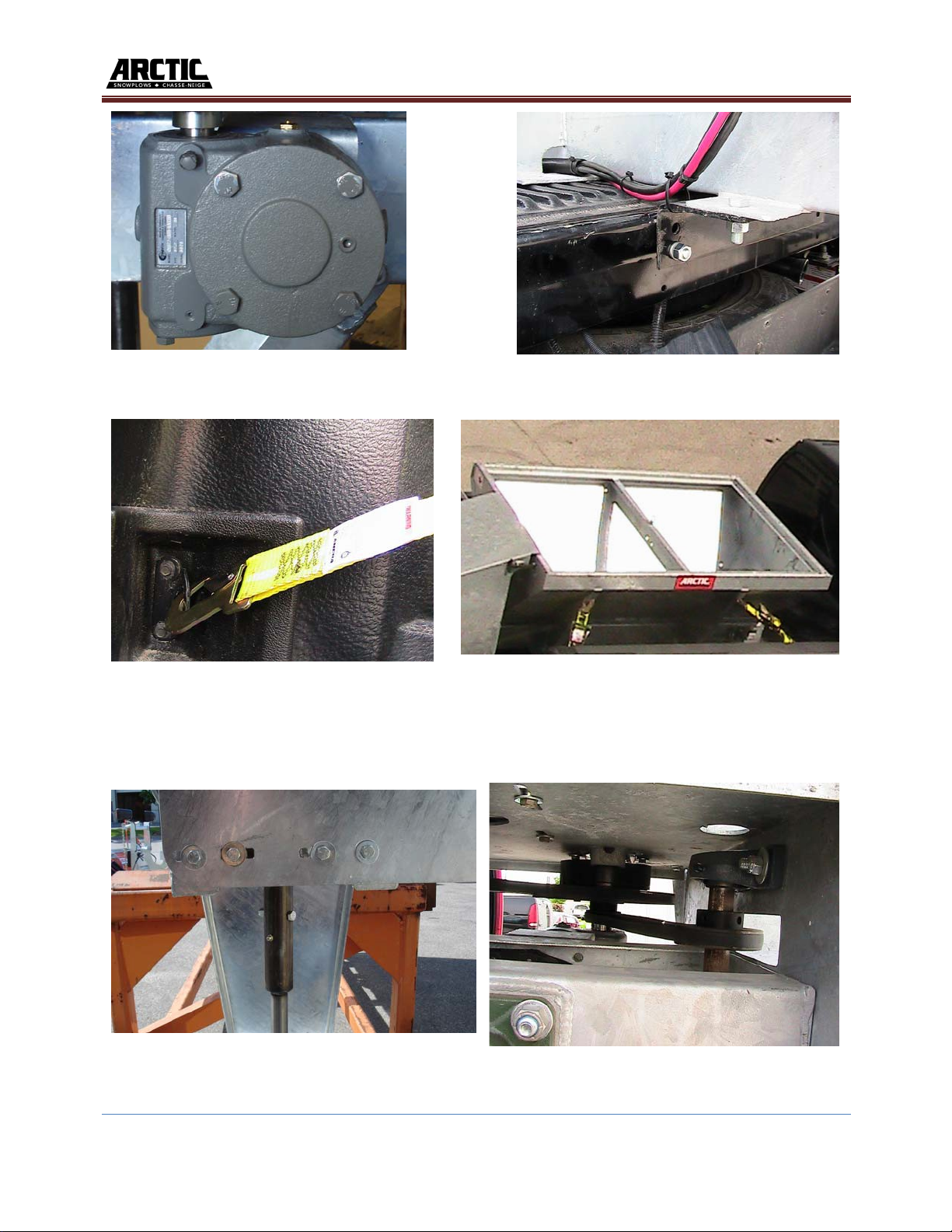
Hydraulic motors, pumps, gear reducer, etc. are also covered under warranty for a period of 1
(one) year, with normal use.
Briggs & Stratton engine is covered for 90 (ninety) days under warranty after the date of
purchase and Honda engine is covered for 2 (two) years after the date of purchase.
Warranty and service of the engine is handled by Honda or Briggs & Stratton dealers.
Arctic Product's Liability is expressly limited to repair or replacement of defective parts. Arctic
Equipment shall not be liable for any consequential, incidental, or contingent damages
whatsoever, whether for breach of contract, breach of warranty, negligence, or other tort, or on
any strict liability theory.
What is not covered under this warranty is specified below.
Warranty does not cover:
- Problems caused by failure to follow instructions and failure to maintain the product as described
in the owner’s manual.
- Damage to the product that has been subject to misuse, neglect, accident, or improper
installation, maintenance, care or storage.
- Damage caused by parts not used in accordance with their intended purpose.
- Paint or surface coating deterioration, expendable parts such as, but not limited to, controller
keypad, bushings, stripped keyways or splines on external shafts, nuts and bolts or tightening nuts
and bolts which are considered normal maintenance.
- Damage resulting from rust, corrosion, freezing or overheating; failure to maintain proper
fluid/lubrication levels.
- Damage due to abrasion of wiring harnesses.
- Travel time incurred to and from dealers or suppliers, accommodations, meals, cost of tax, freight
to/from dealers, storage charges, environmental charges, solvents, sealants, lubricants, or any
other normal shop supplies.
- Problems caused by accessories and parts that are not supplied by Arctic Equipment.
- Damage resulting from lack of, or dirty lubrication or using other than recommended grade and
type of lubrication.
- Running over recommended speeds.
- Repairs by an unauthorized person.
- Damage caused by improper mounting or conditions on units not mounted by factory. Improper
maintenance or storage of equipment

Galvanized Gas Spreader
Page 3
www.arcticsnowplows.com
- Liability for damage to the property, or injury to, or death of any person arising out of the
operation, maintenance or use of the covered product.
This warranty is made only to the original purchaser. There is no other warranty
expressed, implied, or statutory.
The customer must register the equipment with Arctic within 60 days from the day of purchase
using the online registration system found on the Arctic Equipment website
www.arcticsnowplows.com/warranty .
All parts returned to us, transportation charges prepaid, must be accompanied with a
"Return Goods Authorization" number, obtained from the factory. In order to reduce
down-time, we will, on your request, send the parts required and you will be billed under
the usual terms. A credit will be issued to your account when the parts, in our
examination, prove to be defective.
Arctic Equipment Manufacturing Corporation reserves the right to change specification
without prior notice.
Customer Responsibility
The loaded vehicle, including all after market accessories, the salt/sanding equipment,
passengers, and cargo, MUST NOT exceed the gross vehicle weight rating (GAWR),
front gross axle weight rating (FGAWR), or rear gross axle weight rating (RGAWR)
specified on the Safety Compliance Certification Label located in the driver’s side door
opening. It is the operator’s responsibility to verify that these ratings are not
exceeded.
To determine the Gross Axle Weights for your vehicle, including all after market
accessories, the salt/sanding equipment, passengers, and cargo, take your loaded vehicle
to a scale. Place the front wheels of the vehicle on the scale to get the Front Gross Axle
Weights (FGAW). To get the Rear Gross Axle Weights (RGAW), place the back wheels
of the vehicle on the scale.
Disclaimer Notice
Arctic Equipment Manufacturing Corporation (Arctic) does not assume liability for damage
to your motor vehicle resulting from the attachment or use of an Arctic salt/sanding
equipment. The purchaser assumes all vehicle risk associated with the attachment and
operation of this salt/sanding equipment.
The added weight may impair the operation and control of your vehicle. Additional
equipment may be necessary before installing salt/sanding equipment. Please consult
your vehicle dealers prior to the purchase and installation of the salt/sanding equipment.

Galvanized Gas Spreader
Page 4
www.arcticsnowplows.com
WARNING Spreader equipped with gas engine
-
Empty and clean the hopper and wash off all external surfaces after eachuse.
-
Do not overload vehicle. Check vehicle’s load rating certification sticker for maximumvehicle
capacity.
-
Do not exceed GVWR or GAWR with spreader and load. Overloading could result in an
accident or damage.
-
Turn spreader OFF before filling, adjusting, cleaning, servicing or performingmaintenance.
-
Servicing the sander without special tools and knowledge could result in personal injury. See an
authorized Arctic dealer for service.
-
Driver to keep bystanders minimum of 25 feet away from operatingspreader.
-
Before operating the spreader, verify all safety guards are inplace.
-
Before servicing the spreader, wait for conveyor or spinner to stop, and then lock out
power.
-
Avoid touching hot surfaces such as the engine and exhaust pipe.
-
Do not climb into or ride on spreader.
-
Turn off engine and allow it to cool before filling gas tank.
-
DO NOT smoke or use open flame within 25 feet of spreader.
-
Allow spilled gas to evaporate completely before startingengine.
-
Gasoline engine produces poisonous gases while running. DO NOT operate in an enclosed
area.
-
Gasoline engine has hot and moving parts that can cause injury.
-
Use care when working with or near the gasoline engine and its parts.
-
Inspect ratchet straps and tie down bolts before travelling. Parts that are loose, broken, missing
or plainly worn must be tightened or replaced immediately.
-
Shut off engine when not in use, even for short periods of time, to avoid damage toequipment
or property.
-
Do not leave unused material in hopper. Material can freeze or solidify, causing unit to not
work properly. Empty and clean after each use.
-To remove the sander, the unit must be empty. Do not stand close to the sander when it is being
lifted. Keep a safe distance away.
Material Density
(lb per cubic yd.)
Fine Salt – Dry 1400
Coarse Salt – Dry 1300
Coarse Sand – Dry 2800
Coarse Sand – Wet 3300
Operation
These models are powered by a 10.5 H.P. Briggs & Stratton Engine or 11 HP Honda Engine. In
order to provide a smooth transmission of power, the units are equipped with a heavy duty
electrical clutch (picture 14). The gear box (speed reducer) output shaft is what actually drives

Galvanized Gas Spreader
Page 5
www.arcticsnowplows.com
the conveyor. A single V-belt connects Engine and gear box, and the gear box with the spinner
shaft (picture 6, 14 & 15).
The amount of sand and/or salt that is discharged is dependant on two factors. One is the engine
RPM which is controlled by a throttle. An increase in engine RPM not only increases the
discharge rate but the width of spread pattern as well. The other factor that affects the discharge
rate, is the gate opening. Obviously, as the size of the opening increases so will the discharge
rate. A cab mounted switch activates the electric throttle, starter and clutch.
Spreader Installation
The AG6 spreader is designed for installation in a 6'/8' pickup truck bed. The AG8 is designed
for installation in an 8’ pickup truck bed. The AG10 spreader is designed for 10' dump truck or
flat deck truck. Follow the steps below to install your unit in your vehicle.
a)
Slide spreader into position and secure with the ratchet straps into the cargo tie downs of the
truck (pictures # 3 and #4)
b)
Bolt mounting angle bracket to spreader, then bolt it to the back of the truck using ½" bolt.
(Picture #2)
c)
Install the sand chute using the required pivoting/fastening components. (Picture#12)
d)
Assemble the spinner assembly (split shafts), as shown in the assembly drawing in this
manual, using the appropriate components. (Picture #5, 11 and 12)
e)
Position the spinner disc at the desired height and tighten set screws.
You may change the spinner disc height. Using the hole in the spinner disc hub as a guide, drill a
hole through the shaft, for the mounting bolt. Cut off any excess length from the shaft and install
the spinner disc.
f)
Position spinner shaft so it is sitting true (vertical and horizontal) with enough tension on the
spinner belt. (Picture #5 & 6).
g)
Check that belts are aligned on the pulleys (pictures #6, 14, 15) and adjust (ifnecessary).
h)
Apply grease to: split shaft assembly nipples (picture #5), Spinner shaft bearings(picture
#11), drive bearing (picture #7 & 12), idler bearings (picture #8).
Note: Liberally spread grease on the apron chain tensioning bolts (picture #8) to allow for easy
tightening at a later date.
i)
Check and add Oil before Starting and Running (motors are shipped with a minimal amount of
oil in them) Briggs and Stratton Require SAE 30, Honda requires5W30.
j)
Protect wiring harness from rubbing on sharp / hot surfaces. Use loom and zip ties where ever
possible (picture #2 & 9).

Galvanized Gas Spreader
Page 6
www.arcticsnowplows.com
k)
For wiring information see page with wiringinstructions.
l)
Optional - Refer to Hitch Mounted Spinner Shaft Guard installation instructions to further
protect your sander from damage.
Clutch Pre-run setup
Clutches must be burnished before operation. We recommend the clutches be engaged/
disengaged a few times to break them in before being placed under load.
1. Run the engine at 50% throttle.
2. Engage and disengage the clutch 25 times 10 seconds ON and 10 secondsOFF.
3. Run the engine at 75% throttle,
4. Engage and disengage the clutch 25 times 10 seconds ON and 10 secondsOFF.
It is recommended 15-20 ft-lbs of torque on pulley assembly screws
Burnishing procedure must be done on a brand new unit before it is loaded with material.
Never perform the burnishing procedure while drive is loaded.
Starting Up
Check oil level. Oil must be added prior to operation. (Briggs and Stratton requires SAE 30,
Honda calls for 5W-30)
Reasonable precautions should be taken to avoid overloads in the early stage of running.
Temperature rise on the initial run will be higher than the temperature eventually reached after
the gear is fully run in.
Maintenance
Shut off power before inspection. The oil level, in the worm gear unit should be checked at least
once a month. (To check oil level, undo set screw located at the three o’clock position in Picture
#1. Oil should be seen just below this level)
To maintain free ventilation of the unit, the breather hole in the filler plug (air-vent on top of unit
Picture #1) should be kept clear at all times. Inspect regularly the set screw and reducer
mounting bolts for tightness as loose fasteners can cause misalignment and excessivewear.
Changing Lubricant
-
Every year gear box should be drained, flushed and refilled with proper oil.
-
Never mix two different types of oil. Be sure to drain and wash before using another typeof
oil.

Galvanized Gas Spreader
Page 7
www.arcticsnowplows.com
Selection Of Lubricant
Our gearboxes are normally filled up with oil of S.A.E. grade 80W90. Where a wide temperature
range is expected, the synthetic oil MOBIL SHC 634 is recommended. Synthetic lubricants
permit extended life time between drains. This is due to the increased resistance to thermal
degradation or oxidation.
Conveyor Chain Lubrication
When you receive your new spreader, it is not necessary to lubricate the chain. However, when
you store the machine at the end of the season, it is crucial to lubricate it properly to prevent
chain links from seizing. One way is to remove the chain and store it in a lubricant.
Electric System
When you install the spreader, it is very important to put dielectric grease in every connection.
Also, during the season, make sure to inspect the connectors regularly and add dielectric grease
when needed. Also, when the season is over, all connections need to be well cleaned and
lubricated with dielectric grease to prevent corrosion and rust during the storage period.
Before Operating
1)
Engine oil and speed reducer oil level.
2)
Grease all lubrication points.
3)
Ensure all belts are tight.
4)
Ensure that the conveyor chain is dragging for one foot on the bottom return channel, of `
the spreader. (Do not over tighten the chain).
5)
Ratchet straps are in good condition, and all bolts aretight.
Maintenance Inspection
Daily Inspection and Lubrication
a)
Check gearbox oil level. It should be filled to the oil filler plug (Picture#1).
b)
Check engine oil level with dipstick (also check gas).
c)
Lubricate the following grease nipples:
1)
One on each conveyor idler shaft bearing (Picture #8, Item #27 on Parts List)
2)
One on the drive shaft bearing (Picture # 7, Item #19 on PartsList)
3)
One on each (2) spinner shaft bearing (Picture #11, Item #12 on PartsList)

Galvanized Gas Spreader
Page 8
www.arcticsnowplows.com
4)
One on drive shaft coupling (Picture #13, Item #16 on PartsList)
5)
One on split shaft coupling (Picture #5)
d)
It is advisable to clean the air filter element. It can be easily washed out and
reused. At this time, it would be wise to check the drive belts for any appreciable
wear.
e)
Apply dielectric grease in any electric connections periodically.
f)
Inspect ratchet straps and tie down bolts.
Parts that are loose, broken, missing or plainly worn must be tightened or replaced
immediately.
g)
After every use, empty and clean the hopper and wash off all externalsurfaces.
h)
Tighten conveyor chain if required till the point when the center path of the chain
nearly touch the base, making an arc shaped path visible from side view, oil
conveyor chain, if needed for smooth movement of the load.
i)
Remove any trapped or frozen substance that can cause obstruction to the
movement of conveyor chain.
Yearly Inspection
a)
At the end of the operating season, the unit should be thoroughly cleaned and
lubricated (see daily inspection and lubrication). The conveyor chain (picture #10)
could be removed and stored in motor oil or grease. These preventative measures
should prevent premature rusting of the unit. Grease bolts on the chain tighteners
(picture #8).
b)
At this time or before the start of the next season, it is wise to check all drive
components for appreciable wear. Any components which are questionable should be
replaced now. Check that all bolts are tight and ratchet straps are in good condition.
This short and simple check will avoid down time during the operatingseason.
c)
Change the gear box oil (Picture #1).
d)
Parts that are loose, broken, missing or plainly worn must be tightened or replaced
immediately

Galvanized Gas Spreader
Page 1 www.arcticsnowplows.com
Picture #1 Picture #2
Picture #3 Picture #4
Picture #5 Picture #6

Galvanized Gas Spreader
Page 2 www.arcticsnowplows.com
Picture #7 Picture #8
Picture #9 Picture #10
Picture #11
Picture #12

Galvanized Gas Spreader
Page 3 www.arcticsnowplows.com
Picture # 13
Optional Spinner Guard
Picture # 14
Picture # 15

Galvanized Gas Spreader
Page 4 www.arcticsnowplows.com
Installation of electrical throttle for Briggs & Stratton Engine
Electrical Throttle for B&S Engine RC-38880
Item Part# Description Qty.
1 1411907 Throttle motor 1
2 1411910 Throttle pin Assembly 1
3 HH-00013-074 #8-32 x 3/4" Pan Head Machine Screw 3
4 HH-00340-019 #8 Locknut 3
5 90069-A Throttle mounting bracket 1
Note: Mounting bracket needs to be installed using engine mounting bolts.

Galvanized Gas Spreader
Page 5 www.arcticsnowplows.com
Electrical Throttle Kit for Honda Engine RC-38880-01
Item Part# Description Qty.
1 1411907 Throttle motor 1
2 90086-A Throttle mounting bracket 1
3 HH-00013-073 #8-32 x 5/8" Pan Head Machine Screw 4
4 HH-00340-019 #8 Locknut 4
5 90045-N Retainer 1
6 90076-A Harness 1
7 90046-M Handle 1
8 90048-N 2/56 Screw 3
9 90049-N 2/56 Nut 3
10 90050-M Extension Bracket 1
Installation of electrical throttle for Honda Engine
1.
Install throttle motor (1) to the throttle mounting bracket (2) using four #8 screws and nuts
(3)(4). (For correct orientation of the throttle motor (1) see pictures #1, #2, and #3)
2.
Remove two bolts that hold gas tank. Install throttle mounting bracket (2) between engine
body and gas tank. Secure throttle mounting bracket (2) and gas tank using existing tank
bolts.
3.
Using two 2/56 screws and nuts (8)(9) secure extension bracket (10) to the gas engine
bracket (See picture#2).
4.
Install the handle (7) on the throttle motor arm (1). Secure the handle (7) to the throttlemo-
tor arm using the retainer (5). (See picture #3)
5.
Attach handle (7) to the extension bracket (10) using one 2/56 screw and nut (8)(9). (See
picture #2)
6.
One end of the harness (6) attach to the ground (engine bolt) and second attach to Honda
engine light wire. (See picture #4)

If B&S engine is equipped with egulator/rectifier
(square box) and the light on control box stays
on all the time, modify B&S control box as
shown above.

Galvanized Gas Spreader
Page 6 www.arcticsnowplows.com
Picture #1
Picture #2

Galvanized Gas Spreader
Page 7 www.arcticsnowplows.com
Picture #3
Picture #4


90029-02-A
90031-01-A
90031-02-A
WIRING DIAGRAM FOR 8', 10' AND DUMP TRUCK SAND SPREADER
1. The control box 90020-A is to be installed under the dash.
2. Drill hole 1 1/2" in firewall of the truck to attach harness 90028-A to harness 90020-A.
The cable with 3 wires goes under the hood to be attached to the solenoid (installed under hood of the truck).
Second part of harness goes to the back of vehicle. A cable clip is provided at the end of harness so that it can be secured to the truck.
3. Attach the harness 90029-A to the harness 90028-A. Tie harness 90029-A to the sander. End of the harness is attached to the motor, the clutch and the throttle as shown on drawing.
4. Harnesses 90028-A and 90029-A have "dummy" plugs to be attached
when harnesses are not attached to each other for weather protection.
5. Note: If electric throttle runs backwards switch wires 1 and 2 as shown.
6. Red wire on power cable 90030-A is to be attached to solenoid and black wire to be attached
to the vehicle frame (ground). Second power cable 90031-A is attached to cable 90030-A, red wire is attached to motor and
black wire is attached to engine mounting plate.
This manual suits for next models
3
Table of contents
Other Arctic Spreader manuals