Land Pride Primary Seeders PSN2096 User manual

Table of Contents
Cover photo may show optional
equipment not supplied with
standard unit.
© Copyright 2010 Printed
Read the Operator’s manual entirely. When
you see this symbol, the subsequent
instructions and warnings are serious - follow
without exception. Your life and the lives of
others depend on it!
!
20583
313-306M
Operator’s Manual
PSN2096
Primary Seeder
6/28/11

Table of Contents
©Copyright 2010 All rights Reserved
Land Pride provides this publication “as is” without warranty of any kind, either expressed or implied. While every precaution has been taken in the preparation of this manual, Land
Pride assumes no responsibility for errors or omissions. Neither is any liability assumed for damages resulting from the use of the information contained herein. Land Pride reserves
the right to revise and improve its products as it sees fit. This publication describes the state of this product at the time of its publication, and may not reflect the product in the future.
Land Pride is a registered trademark.
All other brands and product names are trademarks or registered trademarks of their respective holders.
Printed in the United States of America.
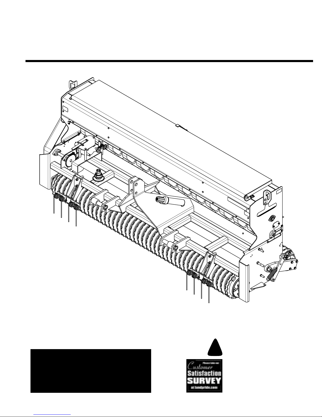
PSN2096 Primary Seeder 313-306M 6/28/11
Important Safety Information . . . . . . . . . . . . . . . 1
Safety at All Times . . . . . . . . . . . . . . . . . . . . . . . . . 1
Look For The Safety Alert Symbol . . . . . . . . . . . . .1
Safety Labels . . . . . . . . . . . . . . . . . . . . . . . . . . . . . 4
Introduction . . . . . . . . . . . . . . . . . . . . . . . . . . . . 10
Application . . . . . . . . . . . . . . . . . . . . . . . . . . . . . . 10
Using This Manual . . . . . . . . . . . . . . . . . . . . . . . . 10
Terminology . . . . . . . . . . . . . . . . . . . . . . . . . . . . 10
Definitions . . . . . . . . . . . . . . . . . . . . . . . . . . . . . 10
Owner Assistance . . . . . . . . . . . . . . . . . . . . . . . . 10
Serial Number Plate . . . . . . . . . . . . . . . . . . . . . . 10
Further Assistance . . . . . . . . . . . . . . . . . . . . . . . 10
Section 1: Assembly & Set-Up (Standard) . . . 11
Tractor Requirements. . . . . . . . . . . . . . . . . . . . . . 11
Torque Requirements. . . . . . . . . . . . . . . . . . . . . . 11
Pre-Assembly Checklist . . . . . . . . . . . . . . . . . . . . 11
Sling Bracket . . . . . . . . . . . . . . . . . . . . . . . . . . . . 11
Tire Track Remover Assembly . . . . . . . . . . . . . . . 11
Section 2: Assembly & Set-Up (Optional) . . . 12
Small Seeds Box Assembly . . . . . . . . . . . . . . . . . 12
Small Seeds Box Drive Assembly . . . . . . . . . . . . 13
Standard Seeds Box Assembly . . . . . . . . . . . . . . 14
Standard Seeds Box Drive Assembly. . . . . . . . . . 15
Section 3: Operating . . . . . . . . . . . . . . . . . . . . . 16
Pre-Start Checklist . . . . . . . . . . . . . . . . . . . . . . . . 16
Tractor Hook-up . . . . . . . . . . . . . . . . . . . . . . . . . . 16
Tractor 3-Point Hook-Up . . . . . . . . . . . . . . . . . . 16
Pull Hitch Hook-Up . . . . . . . . . . . . . . . . . . . . . . . 16
Pull Hitch Disconnect . . . . . . . . . . . . . . . . . . . . . 16
Pull Hitch Operating Instructions . . . . . . . . . . . . . 17
Transporting. . . . . . . . . . . . . . . . . . . . . . . . . . . . . 18
Parking. . . . . . . . . . . . . . . . . . . . . . . . . . . . . . . . . 18
Filling the Seed Box . . . . . . . . . . . . . . . . . . . . . . . 18
Packing Rollers . . . . . . . . . . . . . . . . . . . . . . . . . . 18
How the Seeder Works. . . . . . . . . . . . . . . . . . . . . 19
Operating the Seeder. . . . . . . . . . . . . . . . . . . . . . 19
General Operating Instructions. . . . . . . . . . . . . . . 20
Section 4: Seeding Adjustments . . . . . . . . . . 21
Seed Rate Adjustment . . . . . . . . . . . . . . . . . . . . . 21
Native Grass Seedbox . . . . . . . . . . . . . . . . . . . .21
Seed Rate Speed Change . . . . . . . . . . . . . . . . . . 22
Standard Seeds Box Option . . . . . . . . . . . . . . . .22
Small Seeds Box Option . . . . . . . . . . . . . . . . . . .22
Seed Rate Adjustment . . . . . . . . . . . . . . . . . . . . . 23
Standard Seeds Box & Small Seeds Box . . . . . .23
Seed Rate Charts (Standard Seeds Box) . . . . . . . 24
Seed Rate Charts, Metric (Standard Seeds Box) . 26
Seed Rate Charts (Small Seeds Box). . . . . . . . . . 28
Section 5: Options . . . . . . . . . . . . . . . . . . . . . . 29
Standard Seeds Box. . . . . . . . . . . . . . . . . . . . . . . 29
Small Seeds Box . . . . . . . . . . . . . . . . . . . . . . . . . 29
Pull Hitch . . . . . . . . . . . . . . . . . . . . . . . . . . . . . . . 29
Section 6: Maintenance and Lubrication . . . . 30
Maintenance. . . . . . . . . . . . . . . . . . . . . . . . . . . . . 30
Drive System . . . . . . . . . . . . . . . . . . . . . . . . . . . . 30
Packing Rollers. . . . . . . . . . . . . . . . . . . . . . . . . . . 30
Storage. . . . . . . . . . . . . . . . . . . . . . . . . . . . . . . . . 30
Lubrication . . . . . . . . . . . . . . . . . . . . . . . . . . . . . . 31
Gearbox . . . . . . . . . . . . . . . . . . . . . . . . . . . . . . . 31
Roller Bearings . . . . . . . . . . . . . . . . . . . . . . . . . .31
Roller Chains (4 chains) . . . . . . . . . . . . . . . . . . .32
Roller Chains . . . . . . . . . . . . . . . . . . . . . . . . . . .32
Drive Sprocket Hanger Bearing . . . . . . . . . . . . .32
Roller Chains . . . . . . . . . . . . . . . . . . . . . . . . . . .33
Feed Cup Drive Sprocket Square Bore . . . . . . .33
Axle Pivot . . . . . . . . . . . . . . . . . . . . . . . . . . . . . .34
Locking Mechanism Pivot Points . . . . . . . . . . . .34
Section 7: Specifications & Capacities . . . . . 35
Section 8: Features & Benefits . . . . . . . . . . . . 36
Section 9: Troubleshooting . . . . . . . . . . . . . . . 37
Section 10: Torque & Tire Inflation Charts . . 38
Section 11: Warranty . . . . . . . . . . . . . . . . . . . . 39
Table of Contents

Important Safety Information
PSN2096 Primary Seeder 313-306M 1
Table of Contents
6/28/11
Important Safety Information
▲
These are common practices that may or may not be applicable to the products described in
this manual.
Safety at All Times
Thoroughly read and understand
the instructions given in this
manual before operation. Refer to
the “Safety Label” section, read
all instructions noted on them.
Do not allow anyone to operate
this equipment who has not fully
read and comprehended this
manual and who has not been
properly trained in the safe
operation of the equipment.
▲Operator should be familiar with
all functions of the unit.
▲Operate implement from the
driver’s seat only.
▲Make sure all guards and shields
are in place and secured before
operating implement.
▲Do not leave tractor or implement
unattended with engine running.
▲Dismounting from a moving
tractor could cause serious injury
or death.
▲Do not allow anyone to stand
between the tractor and
implement while backing up to the
implement.
▲Keep hands, feet, and clothing
away from power-driven parts.
▲Wear snug fitting clothing to avoid
entanglement with moving parts.
▲Watch out for wires, trees, etc.,
when raising implement. Make
sure all persons are clear of
working area.
▲Turning tractor too tight may
cause implement to ride up on
wheels. This could result in injury
or equipment damage.
▲Do not carry passengers on
implement at any time.
!Look For The Safety Alert Symbol
The SAFETY ALERT SYMBOL indicates there is a
potential hazard to personal safety involved and extra
safety precaution must be taken. When you see this
symbol, be alert and carefully read the message that
follows it. In addition to design and configuration of
equipment, hazard control and accident prevention are
dependent upon the awareness, concern, prudence and
proper training of personnel involved in the operation,
transport, maintenance and storage of equipment.
Be Aware of
Signal Words
A Signal word designates a degree or
level of hazard seriousness. The
signal words are:
Indicates an imminently hazardous
situation which, if not avoided, will
result in death or serious injury. This
signal word is limited to the most
extreme situations, typically for
machine components that, for
functional purposes, cannot be
guarded.
!DANGER
Indicates a potentially hazardous
situation which, if not avoided, could
result in death or serious injury, and
includes hazards that are exposed
when guards are removed. It may also
be used to alert against unsafe
practices.
Indicates a potentially hazardous
situation which, if not avoided, may
result in minor or moderate injury. It
may also be used to alert against
unsafe practices.
!WARNING
!CAUTION
For Your Protection
▲Thoroughly read and understand
the “Safety Label” section, read all
instructions noted on them.
Shutdown and Storage
▲Lower machine to ground, put
tractor in park, turn off engine, and
remove the key.
▲Detach and store implements in a
area where children normally do
not play. Secure implement by
using blocks and supports.
OFF
REMOVE

Important Safety Information
PSN2096 Primary Seeder 313-306M
2
Table of Contents
6/28/11
Transport
Machinery Safely
▲Comply with state and local laws.
▲Maximum transport speed for
implement is 20 mph. DO NOT
EXCEED. Never travel at a speed
which does not allow adequate
control of steering and stopping.
Some rough terrain require a
slower speed.
▲Sudden braking can cause a
towed load to swerve and upset.
Reduce speed if towed load is not
equipped with brakes.
▲Use the following maximum
speed - tow load weight ratios as
a guideline:
20 mph when weight is less
than or equal to the weight of
tractor.
10 mph when weight is double
the weight of tractor.
▲IMPORTANT: Do not tow a load
that is more than double the
weight of tractor.
Use Safety
Lights and Devices
▲Slow moving tractors, self-
propelled equipment, and towed
implements can create a hazard
whendrivenonpublic roads.They
are difficult to see, especially at
night.
▲Flashing warning lights and turn
signals are recommended
whenever driving on public roads.
Practice Safe
Maintenance
▲Understand procedure before
doing work. Use proper tools and
equipment, refer to Operator’s
Manual for additional information.
▲Work in a clean dry area.
▲Lower the implement to the
ground, put tractor in park, turn off
engine, and remove key before
performing maintenance.
▲Allow implement to cool
completely.
▲Do not grease or oil implement
while it is in operation.
▲Inspect all parts. Make sure parts
are in good condition & installed
properly.
▲Remove buildup of grease, oil or
debris.
▲Remove all tools and unused
parts from implement before
operation.
Use A Safety Chain
▲A safety chain will help control
drawn machinery should it
separate from the tractor
drawbar.
▲Use a chain with the strength
rating equal to or greater than
the gross weight of the towed
machinery.
▲Attach the chain to the tractor
drawbar support or other
specified anchor location. Allow
only enough slack in the chain
to permit turning.
▲Do not use safety chain for
towing.
These are common practices that may or may not be applicable to the products described in
this manual.

Important Safety Information
PSN2096 Primary Seeder 313-306M 3
Table of Contents
6/28/11
Prepare for Emergencies
▲Be prepared if a fire starts.
▲Keep a first aid kit and fire
extinguisher handy.
▲Keep emergency numbers for
doctor, ambulance, hospital and
fire department near phone.
911
Wear
Protective Equipment
▲Wear protective clothing and
equipment appropriate for the job.
Avoid loose fitting clothing.
▲Prolonged exposure to loud noise
can cause hearing impairment or
hearing loss. Wear suitable
hearing protection such as
earmuffs or earplugs.
▲Operating equipment safely
requires the full attention of the
operator. Avoid wearing radio
headphones while operating
machinery.
These are common practices that may or may not be applicable to the products described in
this manual.
Avoid High
Pressure Fluids Hazard
▲Escapingfluidunderpressure can
penetrate the skin causing
serious injury.
▲Avoid the hazard by relieving
pressure before disconnecting
hydraulic lines or performing work
on the system.
▲Make sure all hydraulic fluid
connections are tight and all
hydraulic hoses and lines are in
good condition before applying
pressure to the system.
▲Use a piece of paper or
cardboard, NOT BODY PARTS, to
check for suspected leaks.
▲Wear protective gloves and safety
glasses or goggles when working
with hydraulic systems.
▲If an accident occurs, see a
doctor immediately. Any fluid
injected into the skin must be
treated within a few hours or
gangrene may result.
Keep Riders
Off Machinery
▲Riders obstruct the operator’s
view, they could be struck by
foreign objects or thrown from the
machine.
▲Never allow children to operate
equipment.
Handle
Chemicals Properly
▲Protective clothing should be
worn.
▲Handle all chemicals with care.
▲Follow instructions on container
label.
▲Agricultural chemicals can be
dangerous. Improper use can
seriously injure persons, animals,
plants, soil, and property.
▲Inhaling smoke from any type of
chemical fire is a serious health
hazard.
▲Store or dispose of unused
chemicals as specified by the
chemical manufacturer.

Important Safety Information
PSN2096 Primary Seeder 313-306M
4
Table of Contents
6/28/11
818-543C
DANGER: Guard Missing
(Beneath Guard)
20586
838-111C
DANGER: Keep away, Moving Parts
20586
Safety Labels
Your Primary Seeder comes equipped with all safety labels in
place. They were designed to help you safely operate your
implement. Read and follow their directions.
1. Keep all safety labels clean and legible.
2. Replace all damaged or missing labels. To order new
labels go to your nearest Land Pride dealer or visit our
dealer locator at landpride.com.
3. Some new equipment installed during repair requires
safety labels to be affixed to the replaced component as
specified by Land Pride. When ordering new components
make sure the correct safety labels are included in the
request.
4. Refer to this section for proper label placement.
To install new labels:
a. Clean the area the label is to be placed.
b. Spray soapy water on the surface where the label is to
be placed.
c. Peel backing from label. Press firmly onto the surface.
d. Squeeze out air bubbles with the edge of a credit card.

Important Safety Information
PSN2096 Primary Seeder 313-306M 5
Table of Contents
6/28/11
818-543C
Standard Seeds Box Option
DANGER: Guard Missing
(Beneath Guard)
20593
Standard Seeds Box (Option)
20592
818-055C
SMV: Slow Moving Vehicle
Native Grass Seedbox
20586

Important Safety Information
PSN2096 Primary Seeder 313-306M
6
Table of Contents
6/28/11
818-229C
Amber Reflector
2- Places (Both ends of the main seedbox)
20583
818-230C
Red Reflector
2- Places (Both ends of the main seedbox)
20586
818-230C
Standard Seeds Box Option
Red Reflector
2- Places (Both ends of the Standard Seeds Box)
20593

Important Safety Information
PSN2096 Primary Seeder 313-306M 7
Table of Contents
6/28/11
818-543C
Small Seeds Box Option
DANGER: Guard Missing (Beneath Guard)
20591
838-111C
Small Seeds Box Option
DANGER: Keep away, Moving Parts
20591
818-229C
Small Seeds Box Option
Amber Reflector
2- Places (Both ends of the Small Seeds Box)
20591

Important Safety Information
PSN2096 Primary Seeder 313-306M
8
Table of Contents
6/28/11
27620
27620
27620
838-386C
Pull Hitch Option
Warning: Negative Tongue Weight Hazard
818-337C
Pull Hitch Option
Warning: Excessive Speed Hazard
838-094C
Pull Hitch Option
Warning: High Pressure Fluid Hazard

Important Safety Information
PSN2096 Primary Seeder 313-306M 9
Table of Contents
6/28/11
27622
27622
27622
818-230C
Pull Hitch Option
Caution: Injury or Machine Damage
818-230C
Pull Hitch Option
Danger: Crushing Hazard
818-230C
Pull Hitch Option
Caution: Pinch Point Hazard
2- Places (Outside Plate of Latches)

Introduction
PSN2096 Primary Seeder 313-306M
10
Table of Contents
6/28/11
Owner Assistance
The Warranty Registration card should be filled out by
the dealer at the time of purchase. This information is
necessary to provide you with quality customer service.
If customer service or repair parts are required contact a
LandPride dealer. Adealerhastrainedpersonnel,repair
parts and equipment needed to service the implement.
The parts on your PSN2096 Primary Seeder have been
specially designed and should only be replaced with
genuine Land Pride parts. Therefore, should your
Primary Seeder require replacement parts go to your
Land Pride Dealer.
Serial Number Plate
For prompt service always use the serial number and
modelnumberwhenorderingpartsfromyourLandPride
dealer. Be suretoincludeyourserialandmodelnumbers
incorrespondence also.RefertoFigure 1 forthe location
of your serial number plate.
Serial Number Plate Location
Figure 1
Further Assistance
Your dealer wants you to be satisfied with your new
Primary Seeder. If for any reason you do not understand
any part of this manual or are not satisfied with the
service received, the following actions are suggested:
1. Discuss the matter with your dealership service
manager making sure he is aware of any problems
you may have and that he has had the opportunity to
assist you.
2. If you are still not satisfied, seek out the owner or
general manager of the dealership, explain the
problem and request assistance.
3. For further assistance write to:
Land Pride Service Department
1525 East North Street
P.O. Box 5060
Salina, Ks. 67402-5060
E-mail address
lpser[email protected]
20584
Introduction
Land Pride welcomes you to the growing family of new
productowners.ThisPrimarySeederhasbeendesigned
with care and built by skilled workers using quality
materials. Proper assembly, maintenance, and safe
operating practices will help you get years of satisfactory
use from the Primary Seeder.
Application
The PSN2096 Primary Seeder is ideal for landscaping,
sod farms, grain farms or highway reclamation work. You
can seed Alfalfa, nearly all types of Native Grass and
most types of turfgrass with this seeder. If the majority of
your seeding is done with Native Grass or “fluffy” seeds
likeBig Blue Stem, IndianGrassorSideOatsGrama,the
main seedbox (Native Grass Seedbox) is equipped with
an aggressive picker wheel design to keep seed moving
at a consistent feeding rate.
It is possible to seed three different types of seed at
different rates by adding the smaller optional seed boxes
to the front and back of the main seedbox. The optional
Standard Seeds Box has a 4.8 bushel capacity and is
mounted on the back of the main box. It is equipped with
ourstandard flutedseedcups andagitation to seedmost
turf type grasses as well as a variety of other seeds from
peas to alfalfa. An optional Small Seeds Box with
2 bushel capacity can be mounted on the front and is
used to dispense small seeds such as alfalfa and clover.
See “Specifications & Capacities” on page 35 and
“Features & Benefits” on page 36 for additional
information and performance enhancing options.
Using This Manual
•This Operator’s Manual is designed to help familiarize
you with safety, assembly, operation, adjustments,
troubleshooting, and maintenance. Read this manual
and follow the recommendations to help ensure safe
and efficient operation.
•The information contained within this manual was
current at the time of printing. Some parts may change
slightly to assure you of the best performance.
•To order a new Operator’s or Parts Manual contact
your authorized dealer. Manuals can also be
downloaded, free-of-charge from our website at
www.landpride.com.
Terminology
“Right” or “Left” as used in this manual is determined by
facing the direction the machine will operate while in use
unless otherwise stated.
Definitions
NOTE: A special point of information that the
operator must be aware of before continuing.
IMPORTANT: A special point of information related
to its preceding topic. Land Pride’s intention is that
this information should be read and noted before
continuing.

Section 1: Assembly & Set-Up (Standard)
PSN2096 Primary Seeder 313-306M 11
Table of Contents
6/28/11
Section 1: Assembly & Set-Up (Standard)
Tractor Requirements
This Primary Seeder is designed for tractors with a
3-point Category 2 or 3 and Cat. 2 Quick-Hitch. Tractors
outside the hitch category must not be used. Make
certain that the tractor’s 3-point lifting capacity and
weight is capable of lifting and controlling the seeder
under all operating conditions. Refer to “Specifications
& Capacities” on page 35 for seeder weight.
APull-Typehitch isavailableasanoption. This Pull-Type
Hitch can be used with smaller HP tractors, which may
not have the required capacity to maneuver a
3-point hitch configuration.
The lower 3-point arms must be stabilized to prevent
side-to-side movement. Most tractors have sway blocks
or adjustable chains for this purpose.
Torque Requirements
Refer to “Torque Values Chart” on page 38 to determine
correct torque values when tightening hardware.
Pre-Assembly Checklist
Check Reference
All major frame components. Operator’s
Manual
Location of fasteners and pins.
NOTE: All hardware from the factory has
been installed in the location where it will
be used. If a part is temporarily removed
for assembly reasons, remember where it
goes. Keep parts separated.
Operator’s
Manual
Be sure the part gets used in the correct
location. Use parts manual to identify
location of parts that have been removed
and are unsure where to replace them. By
double checking while you assemble, you
will lessen the chance of using a bolt
incorrectly that may be needed later.
313-306P
Parts
Manual
All working parts are moving freely, bolts
are tight and cotter pins are spread. Operator’s
Manual
All grease fittings are in place and
lubricated. Page 31-34
Proper tension and alignment on all drive
chains. Page 21
Safety decals are correctly located and
legible. Replace if damaged. Pages 4 - 9
NOTE: In order to maintain steering control, ballast
may need to be added to your tractor. Refer to your
tractor’s operator manual to determine if additional
ballast is needed.
Sling Bracket
Refer to Figure 1-1:
The sling brackets on each end of the Native Grass
Seedbox provide points to hook the chain for lifting the
unit. When hooking a chain to the sling brackets, be
certain touse a spreader bar onthe chainor a longchain
to prevent bending the sling brackets.
Sling Bracket
Figure 1-1
Tire Track Remover Assembly
Refer to Figure 1-2:
The Tire Track Removers are assembled 180 degrees
from their operating position for shipping purposes.
1. Remove Track Remover (#1). Keep hardware for
reuse.
2. Flip Track Remover over 180 degrees and
reassemble as shown with 1/2” u-bolt (#4), lock
washers (#3) and nuts (#2). Tighten nuts to the
correct torque.
3. Repeat steps 1&2fortheother side.
Tire Track Remover
Figure 1-2
20577
20589

Section 2: Assembly & Set-Up (Optional)
PSN2096 Primary Seeder 313-306M
12
Table of Contents
6/28/11
Small Seeds Box Assembly
Figure 2-1
20587
Plug These 2 Holes In
The Small Seeds Box
Section 2: Assembly & Set-Up (Optional)
Small Seeds Box Assembly
Refer to Figure 2-1:
1. Remove eight bolts, lock washers and nuts from the
front panel of the Native Grass Seedbox. Plug two
holes in the front of the Small Seeds Box with two of
the removed bolts, lockwashers and nuts.
2. Assemble both ends of the Small Seeds Box (#1)
with four 5/16”-18 x 3/4” bolts (#3), flat washers (#7),
lock washers (#6) and nuts (#5). Do not tighten nuts
until spacers (#2) in step 3 are installed.
3. Align four seedbox spacers (#2) with inner holes of
the Small Seeds Box and Native Grass Seedbox.
Assemble four 5/16”-18 x 3 1/4” bolts (#4), flat
washers (#7), lock washers (#6) and nuts (#5).
4. Tighten nuts (#5) to the correct torque (8 places).
Refer to Figure 2-2:
5. Remove rubber caps (#8) from the small metal
tubes (#9) on the front side of the seed drop
chamber.
6. Attach5/8” seeddrop hoses (#10) to the feedercups
on the Small Seeds Box (#1) with wire clamps (#11).
7. Install drop hoses (#10) over the small metal
tubes(#9)without wire clamps.Trim rubberhosesas
required to remove excess slack.
Cut Away Of Small Seeds Box Drop Tube Assembly
Figure 2-2
27623

Section 2: Assembly & Set-Up (Optional)
PSN2096 Primary Seeder 313-306M 13
Table of Contents
6/28/11
Small Seeds Box Drive Assembly
Refer to Figure 2-3:
1. Place decal “Danger Guard Missing” (#18) and
“Danger Moving Parts” (#19) on the left side in the
locations shown.
2. Placedecal“SeedRate Chart”(#20)underthelidin
the location shown.
3. Assemble chain guard mounts (#5) with 1/4” flange
bolts (#8) and 1/4” flange nuts (#11). Do not tighten
1/4” nuts until step 9 when all drive components and
chain guard (#16) have been installed properly.
Small Seeds Box Drive Assembly
Figure 2-3
20588
4. Install chain idler with spacer (#2) and chain idler
withoutspacer(#3)with1/2”nuts(#9).Donottighten
nuts until step 8.
5. Assemble spacer (#4) and speed change sprocket
assembly (#7) to the welded on 5/8” bolt. Secure
sprocket assembly with 5/8” lock washer (#12) and
hex nut (#10). Tighten 5/8” nut to the correct torque.
6. Assemble front roller sprocket (#13) and key (#1) to
the front roller shaft. Tighten set screws in sprocket.
7. Install #40 x 82 pitch roller chain (#14) first and then
#40 x 118 pitch roller chain (#15).
8. Rotate idlers (#2) and (#3) snug against the roller
chains and hold while tightening 5/8” nuts (#9) to the
correct torque.
9. The chain guard mounts are slotted for easy
assembly. Assemble chain guard (#16) to the chain
guard mounts with knobs (#17). Reposition chain
guard mounts (#5) as needed and tighten nuts (#11)
to the correct torque.

Section 2: Assembly & Set-Up (Optional)
PSN2096 Primary Seeder 313-306M
14
Table of Contents
6/28/11
Standard Seeds Box Assembly
Refer to Figure 2-4:
1. Remove Slow Moving Vehicle Sign (SMV) (#10) with
mounting bracket from the Native Grass Seedbox.
2. Remove 14 bolts, lock washers and nuts assembled
in the rear panel of the Native Grass Seedbox. Plug
thetwoholesintheNativeGrassSeedboxwherethe
SMV sign was mounted with two of the removed
bolts, lockwashers and nuts.
3. Assemble ends of Standard Seeds Box (#1) with
eight5/16”-18x1” bolts (#6),backingplates(#3),flat
washers (#9), lock washers (#8) and hex nuts (#7).
Do not tighten nuts until spacers (#2) in step 4 are
assembled.
4. Align six seedbox mounting spacers (#2) with inner
holes of the Standard Seeds Box and Native Grass
Seedbox. Assemble six 5/16”-18 x 2 1/4” bolts (#5),
flat washers (#9), lock washers (#8) and nuts (#7).
Tighten Small Seeds Box mounting nuts (#7) to the
correct torque.
5. Remove 1 1/2” rubber caps attached to the large
metal tubes in the back of the seeder frame. Attach
11/2” rubberseed droptubes tothe Standard Seeds
Box feeder cups with provided clamps and then
install the drop hoses over the 1 1/2” metal tubes in
the seeder frame. (Clamps not required.)
6. Install SMV sign (#10) with mounting bracket to the
Standard Seeds Box Assembly (#1) with removed
5/16”-18 x 3/4” cap screws (#4), lock washers (#8)
and hex nuts (#7). Tighten nuts to the correct torque.
Standard Seeds Box Assembly
Figure 2-4
20594
Plug 2 Holes

Section 2: Assembly & Set-Up (Optional)
PSN2096 Primary Seeder 313-306M 15
Table of Contents
6/28/11
Standard Seeds Box Drive Assembly
Refer to Figure 2-5:
1. Attach decal “Danger Guard Missing” (#20) to the
right side panel in the location shown. Attach “Seed
Rate Chart” (#21) to the underside of the lid in the
location shown.
2. Attach two chain guard mounts (#3) with
1/4”-20x 5/8” flangebolts (#5)and flange nuts(#10).
Do not tighten nuts until after all drive components
and chain guard (#17) have been installed properly
in step 10.
Standard Seeds Box Drive Assembly
Figure 2-5
20605
3. Screw 1/2” jam nut (#9) onto the lower side panel
stud and then mount lower chain idler (#4) with hex
nut (#7). Do not tighten idler hardware until step 9.
4. Mount upper chain idler (#4) to the Standard Seeds
Box mounting bracket with 1/2”-13 x 1” bolt (#6) and
nut (#7). Do not tighten idler hardware until step 9.
5. Assemble idler sprockets (#18) to chain idlers (#4).
Secure with 1/2” flat washers (#11) and cotter
pins (#13).
6. See “Seed Rate Speed Change” page 22:
Determine which drive type is required and attach
spacers (#2) and speed change sprocket (#1) to the
welded on 5/8” bolt with 5/8” lock washer (#12) and
hex nut (#8). Tighten nut to the correct torque.
7. Assemble sprocket (#14) with existing bolt and lock
washer as shown. Tighten bolt to the correct torque.
8. Install #40 x 150 pitch chain (#16) first and then the
#40 x 72 pitch chain (#15).
9. AdjustchaintensionIdlers(#4)totensionchains and
hold while tightening idler nut (#7) to the correct
torque.
10. The chain guard is slotted for easy assembly.
Assemble chain guard (#17) to the chain guard
mounts with knobs (#19). Reposition chain guard
mounts (#3) as needed and tighten nuts (#10) to the
correct torque.

Section 3: Operating
PSN2096 Primary Seeder 313-306M
16
Table of Contents
6/28/11
Section 3: Operating
Pre-Start Checklist
Hazard control and accident prevention are dependent
upon the awareness, concern, prudence and proper
traininginvolvedintheoperation,transport,maintenance
and storage of the Primary Seeder. Therefore, it is
absolutely essential that no one operates the seeder
without first having read, fully understood and become
totallyfamiliarwiththeOperator’s Manual. Makesure the
operator has completed the Operating Checklist below.
Tractor Hook-up
This Primary Seeder is designed for tractors with a
3-point Category 2 or 3 and Cat. 2 Quick-Hitch. A Pull-
Type hitch is available as an option for smaller
horsepower tractors that do not have the capacity to
maneuver a 3-point configuration.
Tractor 3-Point Hook-Up
1. Back tractor up to the seeder until the lower 3-point
links are aligned with seeder lower hitch clevises.
2. Secure tractor’s 3-point lower arms to the hitch
clevises using hitch pins supplied.
3. Secure tractor’s top center link to the seeder’s top
center hitch using the 1” diameter hitch pin.
4. With seeder resting on level ground, adjust the
tractor’s top center link until seeder is level from front
to back.
Refer to Figure 3-3 on page 17:
5. Removerearrollerlockpinfromparkingpositionand
place in field position.
Operating Checklist
✔Check Page No.
Read and follow all Safety Rules carefully.
Refer to "Important Safety Information". Page 1
Make sure all guards and shields are in place.
Refer to "Important Safety Information". Page 1
Read and follow Assembly & Set-up instructions. Refer
to "Section 1: Assembly & Set-Up (Standard)" and
"Section 2: Assembly & Set-Up (Optional)". Page 11
Read and follow all operating procedures.
Refer to "Section 3: Operating". Page 16
Read all of the “Tractor Hook-Up” and preparation
instructions. Page 16
Read and make all required adjustments.
Refer to "Section 4: Seeding Adjustments". Page 21
Adjust seed rate for the Native Grass Seedbox per the
Native Grass Seed Chart. Page 21
AdjustseedratefortheStandardSeeds BoxandSmall
Seeds Box. See “Seed Rate Charts”. Pages
23 to 28
Read and follow all Maintenance Instructions.
Refer to "Section 6: Maintenance and Lubrication". Page 30
Read and follow all Lubrication Instructions.
Refer to "Lubrication". Page 31
Make sure all gearboxes are properly lubricated.
Refer to Gearbox lubrication. Page 31
Inspect seed cups and seed tubes for foreign matter. Page 37
Check seeder initially and periodically for loose bolts
and pins. Refer to "Torque Values Chart". Page 38
Pull Hitch Hook-Up
!DANGER
Hydraulic fluid under pressure can penetrate skin. Wear
protective gloves and safety glasses or goggles when working
with hydraulic systems. Use a piece of cardboard or wood
rather than hands when searching for hydraulic leaks. If
hydraulic fluid is injected into the skin, it must be treated by a
doctor within a few hours or gangrene may result.
Refer to Figure 3-1 on page 17:
1. Mount tongue of Pull Hitch to tractor drawbar and
secure with safety chain.
2. Connect hydraulic hoses to tractor.
3. Fullyextendliftcylindertoraisetransportwheelsand
lower 3-point pull hitch.
4. Back Pull Hitch up to the seeder to align lower hitch
links with the seeder’s inside smaller hitch pins.
5. Retract lift cylinder to raise lower 3-point hitch links
up until the seeder’s inside smaller hitch pins lock
into the 3-point hitch links.
6. Once pins are locked, adjust lift cylinder up or down
as needed to level the seeder.
7. Withseederlevelandtransportwheelsrestingonthe
ground,adjusttop centerlinkof PullHitch to installin
the bottom holes of the seeder’s upper center hitch.
(Top center hitch pin is provided by the customer)
Pull Hitch Disconnect
Refer to Figure 3-1 on page 17:
!CAUTION
The seeder will have negative tongue weight when it is lifted
off the ground. Lower the seeder to the ground before
proceeding with Pull Hitch disconnect. (Negative tongue
weight is when most of the weight is to the rear of the
implement causing the front of the tongue to be light and may
rise up when disconnected.)
1. Remove top center hitch pin.
2. Flip locking release handles up.
3. Fully extend lift cylinder to lower 3-point hitch until
hitch links are free from lower hitch pins.
IMPORTANT: The lower link handles should be in
the down position before preceding.

Section 3: Operating
PSN2096 Primary Seeder 313-306M 17
Table of Contents
6/28/11
Transport Valve (Shown “ON” for Field Work)
Figure 3-2
Rear Roller Pin in Field Position
Figure 3-3
Turn Transport Valve Handle 90oTo shut
Hydraulics “OFF” For Transporting
27621
20585
Field Position
Park
Position
Pull Hitch Operating Instructions
Refer to Figure 3-1:
1. See Section 2, “Pull Hitch Hook-Up” on page 16 for
hook-up instructions.
Refer to Figure 3-2:
2. Turn transport valve “OFF” before transporting from
site to site. This will protect the seeder from being
damaged should the hydraulic system break.
Refer to Figure 3-3:
3. At the field site, remove rear roller lock pin from park
position and place in field position.
4. Turn transport valve “ON” as shown in Figure 3-2.
5. Raise transport wheels to lower the seeder until it is
restingontheground.Transportwheelsmustalsobe
resting on the ground to support some of the
seeder’s weight.
6. Set tractor hydraulic lever to return lift cylinder to this
position each time the seeder is raised and lowered.
7. With seeder and transport wheels resting on level
ground, readjust top center link on the Pull Hitch to
level the seeder from front to back.
IMPORTANT: Always operate seeder with transport
wheels on the ground and seeder level to prevent
dirt build-up and seeder damage.
Pull Tongue Assembly
Figure 3-1
Top Center Link
Locking Release
Handles
Lift Cylinder Hitch Links
20739
Bottom Holes of
Upper Center Hitch
Inside Smaller
Pins

Section 3: Operating
PSN2096 Primary Seeder 313-306M
18
Table of Contents
6/28/11
Transporting
!CAUTION
When traveling on public roads whether at night or during the
day, use accessory light and devices for adequate warning to
operators of other vehicles. Comply with all federal, state and
local laws.
1. It is best to transport on the road with an empty box
unless necessary as the increased seed weight will
increase the chances for road problems.
2. Whentransporting witha PullHitch, be sureto follow
guide lines under “Pull Hitch Operating Instructions”
on page 17.
3. Select a safe ground speed when transporting from
one site to another. Never exceed 20 miles per hour
travel speed. When traveling on roadways, transport
in such a way that faster moving vehicles may pass
you safely.
4. Reducetractorgroundspeedwhenturningandallow
enough room to keep the seeder from contacting
obstacles such as buildings, trees or fences.
5. Shift tractor to a lower gear when traveling over
rough or hilly terrain.
Rear Roller Pin Parking Position
Figure 3-4
Parking
Refer to Figure 3-4:
The following steps should be done when preparing to
store the seeder or unhitch it from the tractor. See also
“Storage” on page 30 for additional information on long
term storage of your seeder.
1. Park seeder on a level, solid area.
2. Shut tractor engine off and engage parking brake.
3. To prevent the seeder from tipping over backward,
remove rear roller lock pin from field position and
place in park position as show in the figure.
4. Chock front & back rollers to keep unit from moving.
5. Unhitch from tractor.
20579
Park
Position
Filling the Seed Box
!CAUTION
Always lower the Primary Seeder to the ground before filling
and checking seed level in the seed box. This will keep the
rollers from turning while working around them.
1. Always lower the Primary Seeder to the ground,
engage tractor park brake, shut tractor engine off
and remove key before filling the seed box.
2. Release lid latch and open seed box lid until over
centerlatcharmshavelockedinplace.Doingthiswill
keep the lid from falling while filling the box.
3. Fill seed box from the rear while standing on the
ground. Do not step or climb on the rear roller to fill
the seed box. Make sure the rear roller is on the
ground so it cannot turn while filling the box.
4. The bag opener (sharp point on top of baffle plate
located inside the seed box) can be used to tear
open the seed bags.
5. Maker certain the seed box is filled uniformly to
insure one side dose not run out of product ahead of
the other side.
6. Close lid by pulling on the handle of the over center
latcharmswithonehandwhileholdingthelid up with
the other hand. Lower lid gently while keeping hands
and fingers clear.
7. Lock lid down with lid latch to keep moisture out.
Packing Rollers
Refer to Figure 3-5:
The front and rear packing rollers should turn freely. If
they do not, investigate and remove the cause.
The rear roller assembly should be free to float up and
down to follow the field terrain. Remove rear roller lock
pin from park position and place in field position as
shown to free up the roller’s floating capabilities.
Rear Roller Pin in Field Position
Figure 3-5
20585
Field
Position
Other manuals for Primary Seeders PSN2096
1
Table of contents
Other Land Pride Spreader manuals
Popular Spreader manuals by other brands

GroundsKeeper
GroundsKeeper 3042650 Assembly instructions

Simplex
Simplex S2000A Operating instructions manual

Echo
Echo RB-100W Operator's manual

abi
abi 3H Setup guide

Earth Way
Earth Way EV-N-SPRED C22HD Assembly and operating instructions

Earth Way
Earth Way FLEX-SELECT F80 Series Assembly and operating instructions

Earth Way
Earth Way Ev-N-Spred 2050 Assembly and operating instructions

Salt Dogg
Salt Dogg TGS06 installation instructions

Earth Way
Earth Way M30 Operation and assembly manual

BUNNING
BUNNING FarmStar 60 owner's manual

Trynex International
Trynex International SnowEx Precision Pro SP-1675 owner's manual

Buyers
Buyers ATVS100 installation instructions