manuals.online logo
Brands
  1. Home
  2. •
  3. Brands
  4. •
  5. Modulift
  6. •
  7. Spreader
  8. •
  9. Modulift CMOD 70 User manual

Modulift CMOD 70 User manual

User Instructions
Modulift UK Ltd tel: +44(0)1202 621511 email: [email protected] www.modulift.com
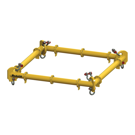
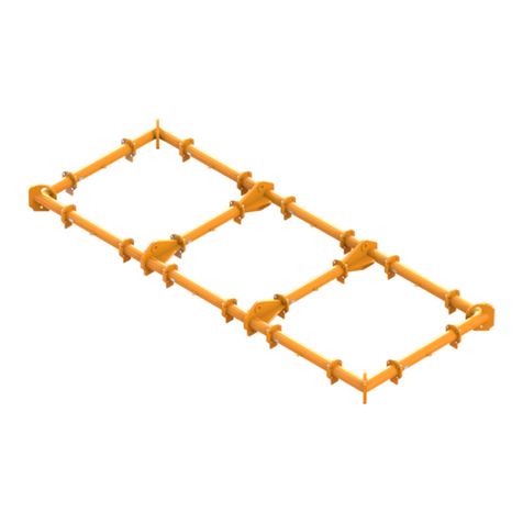
The CMOD Spreader Frame is modular in span and every frame consists of 4 Corner Units,
with intermediate Struts that can be bolted into the assembly to achieve dierent spans.
 Personnel using this system should be suitably trained, competent and have a clear
understanding of Safe Slinging procedures.
 The use of Modulift equipment must be in accordance with the procedures laid down in
‘Lifting Operations and Lifting Equipment Regulations 1998’ (LOLER).
 Never exceed stated WLL – Adhere to WLL in Table 2 for particular sling angle used.
 The top sling length is critical to the safe use of the spreader – Ensure you refer to the correct table.
WARNING!
β = Sling to vertical angle (STV)
CMOD 70 Spreader Frame
CMOD 70 has an assembled span ranging from 1m by 1m to 12m by 12m and all spans inbetween.
CMOD 70 Frame Specication
 Rated at a maximum of 80 tonnes WLL.
Please see Table 2 for WLL at specic spans.
 ‘Sling to Vertical’ angle, β, 45 degrees or less.
 Corner Units are rated at 20 tonnes each
(80 tonnes combined capacity).
 Bolt tightening torque: 150Nm. Spanner size required: 30mm.
 Recommended additional equipment: Torque Wrench, Podger Spanner and Ring Spanner.
Table 1 – Component List
Part Ref. Description Weight/item
P1 Corner Unit(length 0.5m each) 180kg
P2 4.0m Strut 240kg
P3 2.0m Strut 136kg
P4 1.0m Strut 85kg
P5 0.5m Strut 61kg
P6 42.5t Shackle 29kg
P7 35t Shackle 20kg
P8 M20 x 65, Grade 8.8, HT Bolts, Nuts & Washers
P7P2–P5
Span
β
P6
P1 P8
Strut Corner Unit
Assembled
Frame
Fig. 1 – Typical CMOD Spreader Frame Assembly
Modulift UK Ltd tel: +44(0)1202 621511 email: [email protected] www.modulift.com
User Instructions
Should you nd your equipment is no longer of use,
please dispose of in a responsible manner. Please
contact Modulift if you need further guidance
Table 2 – Load v Span
First pick the span required for your frame (e.g.
2m x 5m) and the Sling Angle (we recommend 30°
STV where possible), then check the WLL via the
appropriate table. Read the table by locating the
lower span on the y axis of the chart and the larger
on the x. The cell which you are referred to, will
indicate the WLL for your chosen span. If your exact
span is not noted in the table, then please round up
or down to the values that will give you the lowest
WLL (to ensure no overloads are applied). Please
contact Modulift for conrmation on your WLL if
required. WLL given in tonnes.
© Copyright 2019 Modulift.
All rights reserved.
Assembly Procedure
 Check the ID plates on each Modulift component to
ensure the correct size is used.
 Lay out the Struts and Corner Units in the correct
conguration.
 Check that all anges are clear from debris, sand etc.
before connection.
 Bolt the components together* using bolts, nuts & washers
provided. Tighten the bolts to torque as shown overleaf.
 Loop the top Shackles through the bows of the Corner
Units so they contact ‘bow-to-bow’. The eye of the top
slings can then be passed through the jaws of the Shackles
and the pins replaced.
 Loop the bottom Shackles through the eyes of the drop
slings and connect to the bottom of the Corner Unit with
the Shackle pin.
 Attach the lower slings to the load to be lifted.
 The assembled Spreader Frame and lifting rig must be
thoroughly checked by a competent person prior to lifting.
*The use of a Podger Spanner will aid in assembly by helping
to align the bolt holes by forcing it through.
Do’s & Don’ts
 Do ensure that the frame is only loaded at the Corner Units
and they are all equally loaded.
 Do ensure enough clearance between frame and the load
to prevent the load hitting the frame. Any collision could
cause failure of the frame.
 Do not undertake a lift without the correct use of
appropriate top slings.
 Do not hang any loads from the Strut tube or anges.
 Do not exceed the stated WLL for your span.
 Do not rig the lower slings more than 6° from vertical.
WARNING!
 Do not under any circumstances hang load(s) from the
tube or anges – the Spreader Frame is designed for
compression – not bending.
 Ensure that the top Shackle contacts the bow of the corner
plate ‘bow-to-bow’.
 The CMOD system is designed in accordance with BS
EN13155: Cranes, Safety, Non- xed Load Lifting Attachments.
 Max number of Struts allowed in assembly: 5 per side
 Assemble longer Struts in the centre of the conguration
 Sling angle is crucial to safe use of frame.
 The top sling must be positioned centrally in the Shackle
pin to ensure even loading. Contact your Modulift
supplier for supply of loose spacers where required.
CMOD 70 UK JAN 2019
CMOD 70 Spreader Frame
12 63
11 70 60
10 80 70 58
980 80 70 55
880 80 80 67 53
780 80 80 70 65 51
680 80 80 70 60 62 49
580 80 80 80 70 60 60 47
480 80 80 80 80 70 60 58 46
380 80 80 80 80 80 70 60 56 45
280 80 80 80 80 80 70 70 60 55 44
180 80 80 80 80 80 80 70 70 60 54 44
Span
(m) 123456789101112
CMOD 70: WLL / tonnes @ 30° STV
12 36
11 40 34
10 40 40 33
946 40 40 31
857 46 40 38 30
760 57 46 40 37 29
660 60 57 40 34 35 28
560 60 60 50 40 34 34 27
460 60 60 60 50 40 34 33 26
360 60 60 60 60 50 40 34 32 26
260 60 60 60 60 60 50 40 34 31 25
160 60 60 60 60 60 60 50 40 34 31 24
Span
(m) 123456789101112
CMOD 70: WLL / tonnes @ 45° STV

Other Modulift Spreader manuals

Modulift CMOD 110 User manual

Modulift

Modulift CMOD 110 User manual

Modulift CMOD 50 User manual

Modulift

Modulift CMOD 50 User manual

Modulift MOD 70 User manual

Modulift

Modulift MOD 70 User manual

Modulift CMOD 34 User manual

Modulift

Modulift CMOD 34 User manual

Popular Spreader manuals by other brands

CEMO SW 50 operating instructions

CEMO

CEMO SW 50 operating instructions

LEHNER SuperVario Operating instructions with spare parts list

LEHNER

LEHNER SuperVario Operating instructions with spare parts list

Sulky DX 20 Original instructions

Sulky

Sulky DX 20 Original instructions

Glasdon ICEMASTER 50 Instruction leaflet

Glasdon

Glasdon ICEMASTER 50 Instruction leaflet

Rauch AXENT Series Operator's manual

Rauch

Rauch AXENT Series Operator's manual

SnowEx SP-2400 Owner's/operator's manual

SnowEx

SnowEx SP-2400 Owner's/operator's manual

Meyer V-MAX 2636 Operators Operator's manual

Meyer

Meyer V-MAX 2636 Operators Operator's manual

Shindaiwa RS76 owner's manual

Shindaiwa

Shindaiwa RS76 owner's manual

Vicon RO-C Series user manual

Vicon

Vicon RO-C Series user manual

SnowEx Sidewalk-Pro SD-95 instruction manual

SnowEx

SnowEx Sidewalk-Pro SD-95 instruction manual

Fisher 110 owner's manual

Fisher

Fisher 110 owner's manual

Meyer's VB280 INSTRUCTION AND PARTS BOOK

Meyer's

Meyer's VB280 INSTRUCTION AND PARTS BOOK

Bush Hog MS1300P Operator's manual

Bush Hog

Bush Hog MS1300P Operator's manual

TurfEx TS-85 Owner's/operator's manual

TurfEx

TurfEx TS-85 Owner's/operator's manual

HYDRA-PULL HP 700 Operation and parts manual

HYDRA-PULL

HYDRA-PULL HP 700 Operation and parts manual

EASTMAN PACEMAKER Instruction Manual & Illustrated Parts List

EASTMAN

EASTMAN PACEMAKER Instruction Manual & Illustrated Parts List

TurfEx TS-95 Owner's manual and installation instructions

TurfEx

TurfEx TS-95 Owner's manual and installation instructions

Precision DS1000D Instructions-parts list

Precision

Precision DS1000D Instructions-parts list

manuals.online logo
manuals.online logoBrands
  • About & Mission
  • Contact us
  • Privacy Policy
  • Terms and Conditions

Copyright 2025 Manuals.Online. All Rights Reserved.