C-1 INSTALLATION C-1
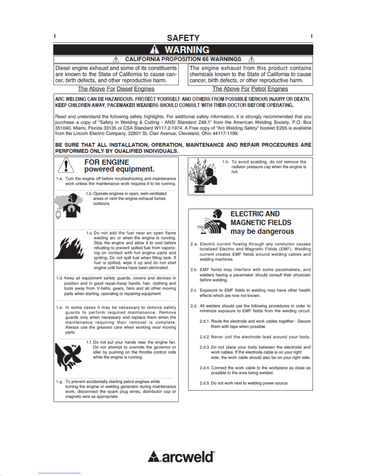
SAFETY PRECAUTIONS
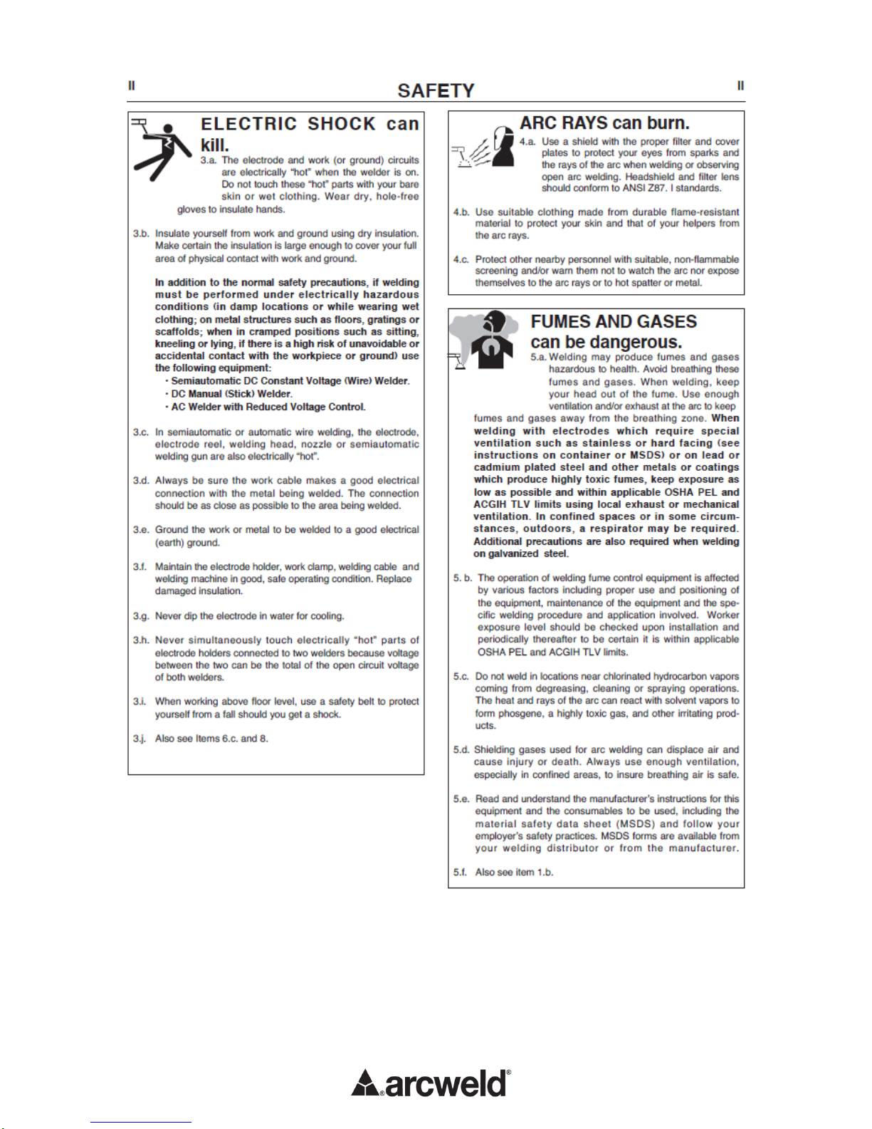
ELECTRIC SHOCK can kill.
Only qualified personnel should
perform this installation.
Turn the input power OFF at the
main switch or fuse box before
working on this equipment.
Do not touch electrically live parts or electrode
with skin or wet clothing.
Insulate yourself from work and ground.
Always wear dry insulating gloves.
FUMES AND GASES can be dan-
gerous.
Keep your head out of fumes.
Use ventilation or exhaust to
remove fumes from breathing zone.
WELDING SPARKS can cause fire or
explosion.
Keep flammable material away.
Do not weld on closed containers.
PLEASE SEE ADDITIONAL WARNING INFORMATION
AT THE FRONT OF THIS OPERATOR’S MANUAL.
SELECT A SUITABLE LOCATION
This power source should not be subjected to rain, nor
should any parts of it be submerged in water. Doing
so may cause improper operation as well as pose a safety
hazard. The best practice is to keep the machine in a dry,
sheltered area.
The bottom of machine must always be placed on a firm,
secure, level surface. There is a danger of the machine
toppling over if this precaution is not taken.
Place the welder where clean cooling air can freely circulate
in through the front louvers and out through the rear louvers.
Water, dirt, dust or any foreign material that can be drawn into
the welder should be kept to a minimum. Failure to observe
these precautions can result in excessive operating temperatures
and nuisance shutdowns..
Locate the arcweld®machine away from radio
controlled machinery. Normal operation of the welder may
adversely affect the operation of RF controlled equipment,
which may result in bodily injury or damage to the equipment.
INPUT CONNECTIONS
ELECTRIC SHOCK can kill.
Have a qualified electrician install and
service this equipment.
Disconnect input power by removing
plug from receptacle before working
inside machines. Allow machine to sit
for 5 minutes minimum to allow the
power capacitors to discharge before
working inside this equipment.
Do not touch electrically live parts.
INPUT POWER CONNECTION
Check the input voltage, phase, and frequency
supplied to thismachine before turning it on. The
allowable input voltage is indicated in the
technical specification section of this manual
and on the rating plate of the machine. Be sure
that the machine is earthed (grounded).
INPUT VOLTAGE
The arcweld®180C MIG machine is to be
provided with a 220V±10% input voltage,
50/60Hz.
An output guide is provided in the technical
specification section of this manual.
ENGINE DRIVEN GENERATOR
The machine is designed to operate on engine
driven generators as long as the auxiliary can
supply adequate voltage, frequency and power
as indicated in the “Technical Specification”
Installation Section of this manual. The auxiliary
supply of the generator must also meet the
following conditions:
Frequency: in the range of 50 and 60 Hz
RMS voltage of the AC waveform: 180-260V
Peak voltage max. 367V
Generator Minimum 8kVA
It is important to check these conditionsbecause
many engine driven generators produce high
voltage spikes. Operation of this machine with
engine driven generators not conforming to
these conditions is not recommend and may
damage the machine and is also NOT covered
by warranty.