TECNA 8201N User manual

RESISTANCE WELDERS
ITEM 8201N ÷ 8214N
INSTALLATION AND USE
INSTRUCTION MANUAL
TECNA S.p.A. Via Grieco 25/27 - 40024 Castel S. Pietro Terme - Bologna ITALY
Pho.+39.051.6954400 – Tel.051.6954410 – Fax.+39.051.6954490
DOCUMENT
NUMBER: MAN 1017 DISTRIBUTOR:
EDITION: MAY 2008

tecn@
WELDERS ITEM 8201N ÷ 8214N
EDITION: MAY 2008 PAGE 2 OF 32
INDEX
CONTENTS PAGE
1 INTRODUCTION 3
1.1 PRELIMINARY REMARKS 3
1.2 SYMBOLS ON BOTH WELDER AND MANUAL 3
1.3 STANDARD ACCESSORIES 3
2 TECHNICAL FEATURES 4
2.1 IDENTIFICATION DATA 4
2.2 ELECTRICAL DATA 4
2.3 MECHANICAL DATA 5
2.4 COMPRESSED AIR CONNECTIONS DATA 5
2.5 COOLING CIRCUIT CONNECTIONS DATA 6
2.6 ADDITIONAL FEATURES 6
2.7 WELDER MAIN FEATURES 7
2.8 STANDARD WELDING CONTROL UNIT TE550 DESCRIPTION 7
3 INSTALLATION 9
3.1 PLACE OF INSTALLATION 9
3.2 UNPACKING AND TRANSPORT 9
3.3 PNEUMATIC INSTALLATION 9
3.4 COOLING WATER CONNECTION 10
3.5 ELECTRICAL INSTALLATION 10
4 WORKING PROCESS 11
4.1 MECHANICAL SET UP 13
4.2 ELECTRODE FORCE ADJUSTMENT 15
4.2.1 STANDARD PNEUMATIC CIRCUIT ADJUSTMENT 15
4.2.2 LOW FORCE SQUEEZE PNEUMATIC CIRCUITS ADJUSTMENT 16
4.3 WORKING PROGRAM ADJUSTMENT 17
4.4 CALCULATION OF THE MAXIMUM WELDING RATING 18
5 SAFETY RULES 19
6 ACCESSORIES AND SPARE PARTS REQUEST 20
7 MAINTENANCE 21
7.1 ORDINARY MAINTENANCE 21
7.2 EMERGENCY CONDITION WARNINGS 22
7.3 EXTRAORDINARY MAINTENANCE 22
7.3.1 LOWERING OF THE WELDING UNIT PERFORMANCES 23
7.3.2 TROUBLESHOOTING 23
7.3.3 REMEDIES FOR WELDS IMPERFECTIONS 26
8 ENCLOSURES 27
8.1 WELDING TABLES 27
8.2 PRODUCTION FORM FACSIMILE 31

tecn@
WELDERS ITEM 8201N ÷ 8214N
EDITION: MAY 2008 PAGE 3 OF 32
1 INTRODUCTION
1.1 PRELIMINARY REMARKS
CAREFULLY READ THIS MANUAL BEFORE INSTALLING AND OPERATING WELDER.
This manual is addressed to the factory responsible in charge who must release it to the
personnel in charge of both welder installation, use and maintenance. He/she must check that
the information given in this manual and in the enclosed documents have been read and
understood. The manual must be stored in a well-known place, easy to reach, and must be
looked up each time even little doubts should arise.
This welder has been designed for resistance welding of both ferrous and not ferrous (aluminium,
brass) materials. The welder must not been used for other application, i.e. pieces heating,
mechanical working carried out by using the electrodes force. The welder has been designed to
be used by an operator by means of the foreseen control devices. All modifications, even slight
ones, are forbidden because they should invalidate the welder CE certification.
The welders described in this manual have been designed to be used only for professional
purposes in industrial environments. They must not be installed on public low voltage network
which supplies domestic premises. This can cause electromagnetic interferences.
TECNA S.p.A is not responsible for any damage to both people, animals, things and to the
welder itself caused by either a wrong use or the lack or the superficial observance of the safety
warnings stated on this manual, nor it is responsible for damages coming from even slight
tampering or from the use of not-suitable spare parts, or of spare parts other than the original
ones.
1.2 SYMBOLS ON BOTH WELDER AND MANUAL
WARNING! Danger of squashing.
Double stroke control device.
WARNING! Important safety information enclosed in this paragraph.
1.3 STANDARD ACCESSORIES
The welder is supplied equipped with the following accessories:
N°1 Allen keys set 4-5-6-8-10 mm.
N°1 Hexagonal key 19 mm.
N°1 Electrodes extractor.
N°1 High conductivity grease pot.
N°1 Straight electrodes, a pair, item 8701.
N°1 Offset electrodes, a pair, item 8703.
N°1 Control unit instruction manual.
N°1 Welder instruction and maintenance manual.
N°1 Technical documentation booklet.
N°1 Wrap-it-ties and hose clamps set.
N°1 Spare silencers set.
Check that the welder is equipped with all the standard accessories; immediately inform the
manufacturer in case some components should lack.

tecn@
WELDERS ITEM 8201N ÷ 8214N
EDITION: MAY 2008 PAGE 4 OF 32
2 TECHNICAL FEATURES
2.1 IDENTIFICATION DATA
Item
Year of manufacturing
Serial number
Supply voltage V
Frequency Hz
Optional:
8230
Valve to stop the flow of the water cooling when the machine is off and flow switch
which makes the welder stop if the cooling water does not circulate.
8232 Rotary selector for the welding program recalling.
8234 Double stroke control device with pneumatic foot instead of key one.
8235 Cylinder 1242 daN (∅125 double stage) total stroke 100 mm.
8236 Adjustable double stroke for cylinder 736 daN (standard).
8237 Adjustable double stroke for cylinder 1242 daN (option 8235).
8238 Low pressure squeeze for cylinder 736 daN (standard).
8239 Low pressure squeeze for cylinder 1242 daN (option 8235).
8240 Proportional valve.
8241 Constant energy operating mode.
2.2 ELECTRICAL DATA
Item
8201N
8202N
8203N
8204N
8206N
8207N
8208N
8209N
8211N
8212N
8213N
8214N
Nominal power at 50 %
duty cycle kVA
63 80 100 125 63 80 100 125 80 100 125 160
Maximum welding power kVA
230 295 420 460 170 230 315 350 135 205 225 650
Short circuit secondary
current kA
40 44 52 54 29 34 39 41 20 25 26 65
Maximum welding current
on aluminium kA
36 40 47 49 26 30 35 37 18 22 23 59
Maximum welding current
on steel kA
32 35 41 43 20 27 31 32 16 20 20 52
Secondary thermal current
at 100 % A
6200 6800 7000 8400 6200 6800 7000 8400 6800 7000 8400 9300
Secondary no load
alternate voltage V
7.1
6.3
5.6
5.0
8.3
7.5
6.7
6.1
10
9
8
7.1
10.5
9
8
7.3
7.1
6.3
5.6
5.0
8.3
7.5
6.7
6.1
10
9
8
7.1
10.5
9
8
7.3
8.3
7.5
6.7
6.1
10
9
8
7.1
10.5
9
8
7.3
12.1
Delayed fuses (380÷415V)
(220÷240V)
A
A
125
200
160
250
200
315
250
400
125
200
160
250
200
315
250
400
160
250
200
315
250
400
315
-
Mains cables section *
380÷415V - L=10m
380÷415V - L=30m
380÷415V - L=60m
220÷240V - L=10m
220÷240V - L=30m
mm
2
mm
2
mm
2
mm
2
mm
2
50
50
95
2x35
2×70
70
70
2×70
2x70
2×95
95
95
2×50
2x95
2×120
2×50
2×50
2×95
2x120
2×150
50
50
70
2x35
2×50
70
70
95
2x70
2×70
95
95
2×35
2x95
2×95
2×50
2×50
2×70
2x120
2×120
70
70
70
2x70
2x70
95
95
95
2x95
2x95
2×50
2×50
2×50
2x120
2x120
2×70
2×70
2×120
-
-
Supply transformer
minimum power ** kVA
266 341 480 532 197 266 364 405 156 237 260 727
* Section for every phase, calculated for PVC insulated, single conductor cables, considering the welder working at
the maximum welding power and a 4% voltage drop on cables.
** Approximate value, calculated for a three phase transformer with a 4% short circuit voltage, with 6% voltage drop
on transformer and a 4% voltage drop on cables, with the welder adjusted for the maximum welding power.

tecn@
WELDERS ITEM 8201N ÷ 8214N
EDITION: MAY 2008 PAGE 5 OF 32
2.3 MECHANICAL DATA
Articolo 8201N-8202N
8203N-8204N
8214N
8206N-8207N
8208N-8209N 8211N-8212N
8213N
Electrodes throat depth L = mm 390 540 800
Projection plates throat depth D = mm 270 420 -
Electrode-holder Standard ∅32 mm
Special ∅.................................................
Electrodes cone Standard ∅19,05 mm 3/4" 2°30' BS 807
Special ∅.................................................
Projection plate Standard centreline 63 mm for M12 nuts
Special .....................................................
Pneumatic circuit Standard
∅125 Optional
∅125 ×2
Electrode force per bar (100 kPa) daN 123 207
Electrode force at 6 bar (600 kPa) daN 736 1242
Maximum stroke mm 100 100
Double stroke mm 60 60
Adjustable Double stroke (options 8236-8237) mm 0÷80 0÷80
2.4 COMPRESSED AIR CONNECTIONS DATA
Minimum pressure bar
6,5
kPa 650
Maximum pressure bar
10
kPa 1000
Hoses minimum inside diameter mm 15

tecn@
WELDERS ITEM 8201N ÷ 8214N
EDITION: MAY 2008 PAGE 6 OF 32
Pneumatic cylinder
Consumption for 1000 spots at 6 bar (600 kPa) Standard
∅125 Optional
∅125 ×2
Standard pneumatic circuit
with maximum working stroke Nm315,4 21,7
with 20 mm stroke and operating
with maximum double stroke Nm34,6 9,4
Pneumatic circuit with low force squeeze (options 8238 - 8239)
with maximum working stroke Nm39,2 15,5
with 20 mm stroke and operating
with maximum double stroke Nm32,9 6
2.5 COOLING CIRCUIT CONNECTIONS DATA
Maximum water pressure bar 4
kPa 400
Hoses inside diameter - input/output mm 12
Minimum consumption for nominal power l/min. 8
2.6 ADDITIONAL FEATURES
Item
8201N 8202N 8203N 8204N 8206N 8207N 8208N 8209N 8211N 8212N 8213N 8214N
Net weight of the
machine kg
510 525 540 555 530 545 560 575 585 600 615 555
Aerial noise produced
(Continuous eqivalent
acoustic pressure
level; A weighed value)
dB(A)
71 73 76 77 72 72 75 75 76 76 76 78
Measurement position h=1,60 m L=0,5 m
Measurement conditions
working stroke (mm)
welding time (cycles)
welding current (kA)
working rating (welds/min.)
50
13
29
6
50
11
34
6
50
10
39
6
50
12
41
6
50
22
22
6
50
21
25
6
50
17
29
6
50
22
30
6
20
23
15
15
20
16
19
15
20
20
20
15
50
11
47
6
Machine painting colour
Grey RAL7035
..............................................

tecn@
WELDERS ITEM 8201N ÷ 8214N
EDITION: MAY 2008 PAGE 7 OF 32
2.7 MAIN WELDER FEATURES
•
Cylinder with chrome plated stem for heavy duty works and long life; adjustable anti-rotation
device.
•
Lubrication free pneumatic components.
•
Electrodes descent without pressure for set up and service.
•
Built-in compressed air filter unit and tank.
•
Silencers for compressed air discharge.
•
Two stage electric foot control for clamping and welding pieces only if correctly positioned.
•Pre-setting for additional double stage electric foot connection for the direct recalling of
welding program no.2.
•
Water-cooled transformer, plates, electrode-holders and electrodes; transformer with epoxy
resin coated windings.
•
Synchronous SCR contactor insulated from cooling water circuit with protection thermostat.
•
Two-hand safety control with timer for maximum safety, and removable key selector, standard
on all models.
•
Emergency push-button to stop the machine immediately.
•
Constant current control unit.
OPTIONS:
8230 - Valve to stop the flow of the water-cooling when the machine is off and flow switch, which
makes the welder stop if the cooling water does not circulate.
8232 - Rotary selector for recalling the welding programs.
8234 - Double stroke control device with pneumatic foot instead of key one. To be used only for
spot welding when the work necessarily requires it.
8235 - Cylinder 1242 daN (∅125 double stage) total stroke 100 mm.
8236 - Adjustable double stroke for cylinder 736 daN.
8237 - Adjustable double stroke for cylinder 1242 daN (option 8235).
8238 - Low pressure squeeze for cylinder 736 daN.
8239 - Low pressure squeeze for cylinder 1242 daN (option 8235).
8240 - Proportional valve. Allows to adjust the working pressure directly from the control unit and
to combine a proper pressure value to each program.
8241 - Constant energy operating mode.
2.8 WELDING CONTROL TE550 DESCRIPTION
The TE550 is a microprocessor-based welding control unit for resistance welders. The task of the
welding control unit is to manage the welder components, in particular the controlled diodes that
carry out the welding current adjustment.
The TE550 is a particularly versatile welding control unit as it may be adjusted to different types
of welders; it may be installed not only on spot and projection welders but on seam welders too. It
may work with power adjustment: both in constant current and in constant energy (optional). The
number of inputs and outputs may be increased so to better adjust the welding control unit to
automatic machines.
It is possible to store up to 250 different welding programs, 31 of which are recalled directly from
an external device. Each program comprises several programmable parameters that describe the
work cycle. In addition to the plain 4-stage welding cycle, the control unit allows the running of
welding processes with pre-welding current, post-welding current, slope and pulses.

tecn@
WELDERS ITEM 8201N ÷ 8214N
EDITION: MAY 2008 PAGE 8 OF 32
MAIN TECHNICAL DATA
•
Simplified programming via 6 keys and a backlit alphanumeric LCD.
•
Synchronous control with controlled diodes, phase control current adjustment.
•
Storage of 250 welding programs, 31 recallable from an external drive.
•
Up to 25 programmable parameters for each program.
•
Slope, pulses, pre-weld, post-weld functions and adjustment of the welding times in half-
cycles.
•
Display of the RMS welding current measurement in kA and relative angle of conduction.
•
3 operating modes: standard, constant current and constant energy.
•
Welding current or angle of conduction limits.
•
Double stroke function.
•
Stepper function to compensate the electrodes wear with programmable curve.
•
Single and automatic cycle. WELD and NO-WELD function.
•
Adjustment of first insertion delay.
•
Control of 5 solenoid valves 24 VDC max. 5 W with self-protected output.
•
Self-adjustment at mains frequency 50/60 Hz.
•
Serial data transmission by means of optional insulated RS232 or RS485 ports.
•
Output for proportional solenoid valve.
•
Key for selecting foot control or two-hand control.
•
Selectable languages: Italian, English, French, German, Spanish, Hungarian, Swedish or
Portuguese.
•
Possibility of upgrading control unit Firmware via appropriate software.
•
Activation and control of the electrodes dressing (optional)
PARAMETER RANGE
WORK MODE IK - FIX
CONTROL MODE NO - CURR - DEG
SQUEEZE 1 01 - 99
SQUEEZE 00 - 99
PRESSURE 1.0 - 10 bar
FORGE DELAY 00 - 99
FORGE PRESSURE 1.0 - 10 bar
PRE-WELD 00.0 - 99.5
PRE-POWER 05 - 99
COLD 1 00 - 50
SLOPE UP 00 - 25
WELD 1 00.5 - 99.5
POWER 1
CURRENT 1 01 - 99
01.0 - 90.0 kA
COLD 2 00 - 50
N. IMPULSE 00 - 09
SLOPE DOWN 00 - 25
COLD 3 00 - 50
POST-WELD 00.0 - 99.5
POST-POWER 05 - 99
HOLD TIME 01 - 99
OFF TIME 00 - 99
CURR. MIN 1.0 - 90.0 kA
ANGLE MIN 001°- 180°
CURR. MAX. 1.0 - 90.0 kA
ANGLE MAX. 001°- 180°
For further information concerning TE550 see the relevant instruction manual.

tecn@
WELDERS ITEM 8201N ÷ 8214N
EDITION: MAY 2008 PAGE 9 OF 32
3 INSTALLATION
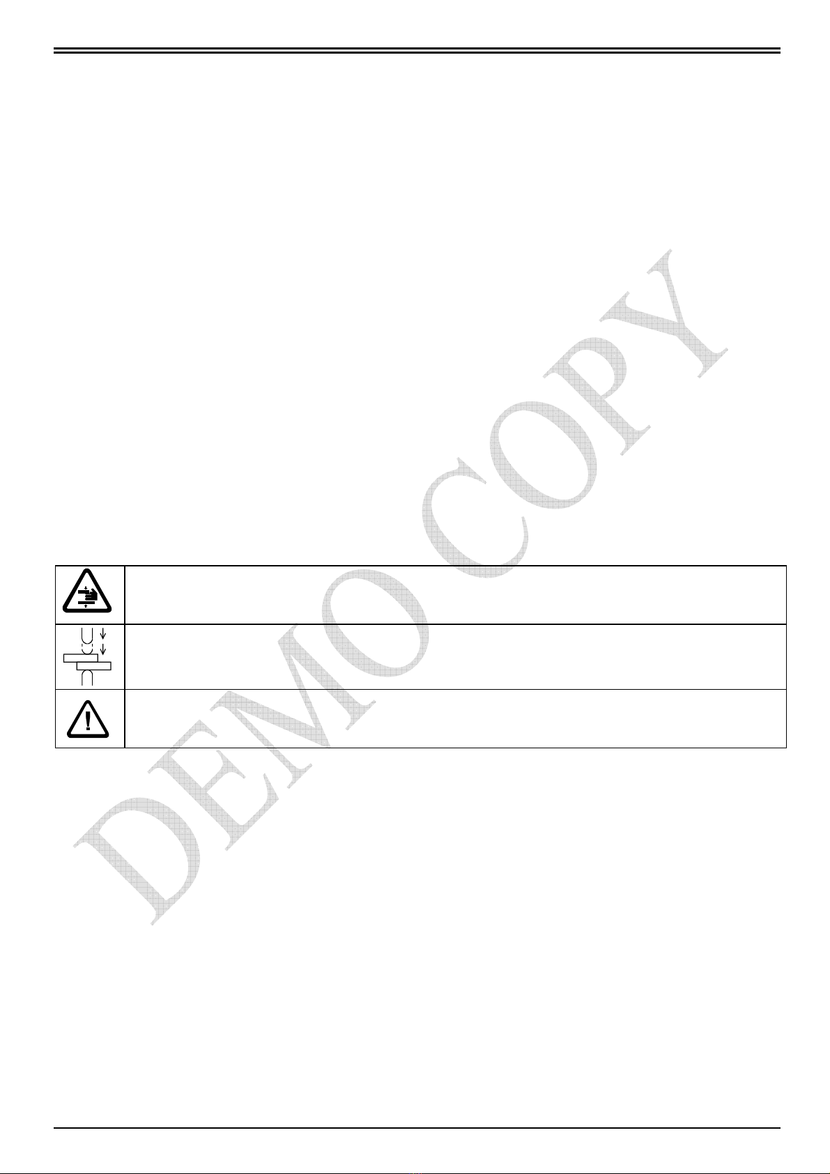
These paragraphs are addressed to the specialised personnel in charge of both welder transport
and installation. The welder dimensions diagram in the technical documentation booklet provides
useful information for carrying out these operations.
3.1 PLACE OF INSTALLATION
The welder must be installed in a position fulfilling the following features:
•In an inner place. The use of the welder in an open place is not foreseen.
•Room temperature included between 0 and 40 °C (If water is removed, storage is allowed
down to 20°C below 0); 1000 m. maximum altitudes.
•In a well ventilated area, free from dust, steam, and acid exhalations.
•The working place must be free from inflammable materials because the working process can
produce spatter of melted metal.
•Around the welder there must be enough room to carry out both working and maintenance in a
comfortable manner and without any risk.
•In a place with a suitable lighting system in comparison with the work to be carried out.
•The place of installation must necessarily be flat and the ground must be without unevenness
which can be dangerous during the working.
If the welder is used to carry out welding processes which can cause smoke exhalations, there
must be installed a proper aspirator. The welder must be properly fixed to the ground through the
proper holes placed on the welder basement. Do not install nearby the welder neither supporting
tables nor equipment limiting the approaching to the devices and/or making inaccessible or
ineffectual the safety devices.
3.2 UNPACKING AND TRANSPORT
On receipt of the welder, verify the perfect integrity of the outer package; communicate to a
responsible in charge possible anomalies which should be noticed. Possible damages on the
outer package should arise some doubts on the integrity of its content. Remove the package and
visually verify the welder integrity. Check that the welder is equipped with all the standards
components; immediately inform the manufacturer in case some components should lack. All the
material forming the package must be removed according to the present environmental
protection regulations.
The welder barycentre is high from ground. For this reason, the welder must be moved only by
means of the proper attachment placed on the unit upper side. Consider the welder weight stated
on the “TECHNICAL FEATURE” paragraph.
3.3 PNEUMATIC INSTALLATION
For a correct compressed air supply to the welder, it is necessary either a centralised system or a
compressor capable of supplying dry air cooled within the maximum pressure and in the quantity
stated in the paragraph “Technical Features”. Pay attention to the hoses minimum diameter
stated in the same paragraph.
In case the line is subject to great pressure variations, it is advisable to supply the welder by
means of a tank of at least 50-100 litres equipped with a gauge-pressure supplied by means of a
one-way valve.
The machine is equipped with a filter unit, the moisture of which must be discharged periodically.
Periodically discharge also the moisture eventually present in the built-in small air tank, by means
of the tap placed on the bottom of the tank itself.

tecn@
WELDERS ITEM 8201N ÷ 8214N
EDITION: MAY 2008 PAGE 10 OF 32
The welder has been assembled by using components which do not require lubrication. The
insertion of a lubricator in the circuit causes no problems to the welder; nevertheless, pay
attention to the fact that this brings the emission of oil mist in the environment.
3.4 COOLING WATER CONNECTION
For a correct cooling of the welder it is necessary clean water at a maximum temperature of 30°C
at the quantity stated on the paragraph “Technical features”. When connecting the unit to the
water line check for dirt or packing scraps in the hoses and connect the supply to the inlet, and
the drain to the outlet, this to allow that still cool water immediately reaches the parts of the
welder most subject to heating.
Different cooling circuit systems are available: with city supply water, with re-circulating water,
with heat exchanger (air-water) and with refrigerator. If the circuit is with city supply or refrigerator
and you are working in presence of high humidity, we suggest to avoid the use of low
temperature water, as this could produce moisture inside the machine. In presence of hard water
it is necessary to install a water softener at the inlet hose, this to avoid that deposits obstruct or
reduce the water channels in the welder causing damages. If the machine is operated in a re-
circulating water supply, the water softener must be placed on the supply of the tank, an insertion
before the machine generate damages.
3.5 ELECTRICAL INSTALLATION
The welders described in this manual have been designed to be used only for professional
purposes in industrial environments. They must not be installed on public low voltage network
which supplies domestic premises. This can cause electromagnetic interferences.
Installation must be carried out by specialised personnel, aware of all safety rules.
As this unit can be supplied for different power supply versions, before connecting the unit to the
power line, check if the voltage shown on the features plate corresponds to the one of your
power supply.
Consult the “technical features” paragraph to determine the cables section to be used, according
to their length. On this paragraph you find also the values of fuses which must be placed on the
welder supply input. Fuses must be delayed type. Connect machine to earth by using a cable
having the same section of the mains cable. In order to facilitate the maintenance operation, we
recommend you to supply the welder machine by means of a mains disconnecting switch. The
welder has not been designed for different voltages supply. If a voltage change is necessary
consult your supplier for the replacement of required parts and new set ups.

tecn@
WELDERS ITEM 8201N ÷ 8214N
EDITION: MAY 2008 PAGE 11 OF 32
4 WORKING PROCESS
The welder has been designed for being used by an operator placed in front of the unit and
working on the same working ground on which the welder is installed.
When arranging the working place, always follow the herewith stated instructions:
•Use a well ventilated area, free from dust, steam, and acid exhalations.
•The working place must be free from inflammable materials because the working can produce
spatter of melted metal.
•Around the welder there must be enough room to carry out both working and maintenance in a
comfortable manner and without any risk.
•If the welder is used to carry out welding processes which can cause smoke exhalations, there
must be installed a proper aspirator.
•Do not install on the welder neither supporting tables nor equipment which either limit the
approaching to the devices or make inaccessible or ineffectual the safety devices.
When switching on the welder, besides triggering the main switch, it is
necessary to press also the control unit RESTART button. This device enables
the welding control and supply the service circuit. Before pressing the button,
check that this does not cause damages to both people and tools.
Before starting the working process, carry out the following adjustments:
1 - Mechanical set up
2 - Electrode force adjustment
3 - Welding parameters adjustment
4 - Calculation of the maximum welding rating
The following paragraphs carefully explain these different phases.
Before starting the working process:
•Check that all the safety instructions have been operated.
•Check that the correct device have been selected (by means of the TWO-HANDS /
FOOT CONTROL selector). Each time the type of production allows it, it is compulsory to use
the unit by means of the push-buttons control device. The control device which is not
employed must be detached and removed from the working place. Remember that on the
control unit there is a 2 positions removable key-switch preventing the operator from freely
modify the working conditions (with the consequent risk of altering the safety conditions); for
further information, refer to the control unit instruction manual.
•Additional foot-control (which is supplied on request): if it is not used when working, disconnect
it and remove it from the working place.
•Check that the automatic cycle is inserted only when it is really used.
•Check that the pneumatic circuit is supplied.
•Check the correct functioning of the control devices; at the first stage, the foot control must
have a 10-12 mm stroke.
•Carry out some test cycles in order to verify both the cycle correctness and the operating
speeds. These tests should be carried out without current circulation by means of the
WELD/NO WELD selector placed on the control unit.

tecn@
WELDERS ITEM 8201N ÷ 8214N
EDITION: MAY 2008 PAGE 12 OF 32
Before starting the welding process, check the welding conditions (time, pressure, etc.). If you are
operating spot welding, use two off-cuts of the sheet to weld, carry out two spots at the same
distance used during the production, then remove the first and check the second: the spot is
correct when the pulling test causes the coming out of the weld nugget with the hole of a sheet,
and the twist test shows a pure area without porosity or causes the coming out of the nugget.
Similar considerations and similar tests should be carried out also for projecting welding.
During the production it is advisable to monitor those parameters which can alter the working
conditions and thus the welds quality. If you are operating spot welding, always monitor the
electrodes which must always be clean, without any deformation and must have the proper
diameter according to the work to be carried out. Check that there are not strong changing in the
welder supply pressure as they could modify the force on the electrodes and thus the welding
quality.
Do not use sealing products to remove water losses on the electrodes conic connection. To
facilitate the electrode removal and to prevent from both cone seizure and water losses, use high
conductivity grease similar to the standard one.
The cooling water must circulate inside the welder for a few minutes after having completed the
production in order to allow the welder cooling. To prevent from both losses and moisture
deposits, do not leave the cooling circuit open when the unit is not used.
Electrodes must not be used to force the clamping of the pieces to weld.
We recommend you to notice the adjustments carried out for each type of piece. In order to
make it easier, a specific table has been added at the end of this manual.

tecn@
WELDERS ITEM 8201N ÷ 8214N
EDITION: MAY 2008 PAGE 13 OF 32
4.1 MECHANICAL SET UP
Spot welding electrodes adjustment.
With control unit set to NO WELD, the start device is activated; with the electrodes touching,
contact between electrodes should be uniform. If required, carry out the adjustment. It is
advisable to adjust electrodes with a fine file or with sandpaper. In case of steel welding, the
electrodes diameter should correspond to the values shown on the following table.
Sheet thickness mm 0,5 0,8 1 1,5 2 2,5 3 3,5 4
Required diameter mm 4 4,5 5 6 7 7,5 8,5 9,5 11
Suggested electrode tip angle is 120 degrees. If the thickness of the two plates is different the
electrode must have the diameter corresponding to the one required by the plate to which it gets
in touch.
A too small diameter in comparison with the thickness to be welded produces spatter of melted
material, sheets over mark, low spot quality. If the electrode diameter is too large, longer welding
times are necessary, causing a higher heating of the welder and a shorter life of electrodes. For
aluminium spot welding we suggest to use spherical electrodes, radius value varies according to
the thickness to be welded and the kind of quality required.
Projection welding tools adjustments.
When assembling the tools on the projection plates, carefully follow the herewith stated
instructions:
•Adjust the components in order to have them perfectly combine. To facilitate this operation, on
the welding cylinder left side there is a hand-operated valve which enables the head descent
by discharging the back pressure.
•Welding force must be equally distributed on the different welding spots; for this reason, tools
must be parallel when the desired welding force is applied to them.
•Adjust stroke to the minimum value to increase the tool follow up.

tecn@
WELDERS ITEM 8201N ÷ 8214N
EDITION: MAY 2008 PAGE 14 OF 32
Working Stroke Adjustment
Adjust working stroke as short as possible to get:
1) Higher productivity.
2) Faster pressure rise time on the pieces to weld.
3) Higher follow up.
4) Higher working precision.
5) Reduced labour accident possibility.
6) Reduced air consumption.
7) Reduced noise.
The working stroke can be adjusted either by moving the lower console or, if the unit is spot
welding operated, by moving one of the two electrode-holders.
To adjust the lower console height, first slacken nuts 102, then slacken screws 101. Carry out the
desired adjustment by means of the hydraulic jack, then tighten home first screws 101, then nuts
102.
The stroke adjustment must be carried out in order to avoid that the cylinder reaches the end of
the stroke, limiting or cancelling by doing so the force on the piece. Remind that both electrodes
and tools wear increases the working stroke.
When operating large-sized pieces spot welding it can be necessary to use a high stroke to be
able to insert pieces among the electrodes. To allow the use of a reduced
stroke even when operating in this way, this unit is equipped with a control
device called “double stroke”. A key switch, placed on the welder and marked
with the symbol hereby shown, enables to select two different electrodes gaps:
the working stroke and the great gap used to position the piece. When the
double-stroke is not used, the corresponding control key must be removed in
order to avoid that its employ causes risks.
On request, on some welders it is assembled a foot-control device as the operator, who must
hold the piece to weld, is not able to control also the key switch.
If the welder is equipped with the relevant option, it is possible to adjust the double stroke by
means of the proper hand-wheel placed on the cylinder. Always carry out this operation keeping
the double stroke disabled.

tecn@
WELDERS ITEM 8201N ÷ 8214N
EDITION: MAY 2008 PAGE 15 OF 32
4.2 ELECTRODE FORCE ADJUSTMENT
The following paragraphs show how to adjust both the standard pneumatic circuit, and the
optional one with a low force squeeze. The welding force must be selected taking into
consideration both tables and personal experience, and in relation to the sheets thickness, the
desired spot quality, etc.
Always adjust by keeping the welding control unit on “NO WELD” in order to avoid
any risk caused by a wrong adjustment. Always carry out “NO WELD” cycle tests
before starting the welding process.
An excessive electrodes force can cause:
•
welding over marks;
•
possible electrodes short life;
•
weak welding or false welding due to a reduction of contact resistance, which allows the
current to pass through without bringing the piece to the melting temperature.
An insufficient force on electrodes can cause:
•
spatter of melted material;
•
stuck weld of the pieces on the electrode;
•
welding with a disagreeable outside surface.
If the welding to be carried out requires low or precise force values, it is advisable to use a
dynamometer.
4.2.1 STANDARD PNEUMATIC CIRCUIT ADJUSTMENT
The electrodes force adjustment is carried out by means of the pressure control REG1. This
carries out the pressure P1 adjustment, (displayed by pressure gauge MAN1), modifying the
welding force.
Upon demand, it is possible to have a proportional valve EVP to adjust the working pressure
directly from the control unit and to combine a proper pressure value to each program. Assures
constant and accurate working pressure.
The reached force values, concerning the different pressure values showed on the pressure
gauge, are listed in the following table:
PRESSURE CYLINDER ∅125
(STANDARD) CYLINDER ∅125 ×2
(OPTION 8235)
bar kPa FORCE in daN FORCE in daN
0,5 50 61 103
1 100 122 207
2 200 245 414
3 300 368 621
4 400 490 828
5 500 613 1035
6 600 736 1242
The head descent speed adjustment is carried out by means of the flow regulator RFL2; the rise
speed adjustment is carried out by means of the flow regulator RFL1. The flow regulator RFL3
must be used in order to carry out the double stroke descent speed adjustment.

tecn@
WELDERS ITEM 8201N ÷ 8214N
EDITION: MAY 2008 PAGE 16 OF 32
4.2.2 LOW FORCE SQUEEZE PNEUMATIC CIRCUITS ADJUSTMENT
(OPTIONS 8238-8239)
On request, the welder can be equipped with a pneumatic circuit enabling the low force squeeze,
useful especially for projection welding and with light alloys. The pneumatic circuit functioning
varies according to the used pneumatic cylinder:
SINGLE STAGE (STANDARD) DOUBLE STAGE (OPTION 8235)
The head low force descent is obtained by
supplying both the cylinder lower and upper
chamber. When the descent is over (after the
1° SQUEEZE) the back pressure is removed
in order to obtain the welding force.
The head low force descent is obtained by
supplying both the cylinder lower chamber and
one of the cylinder upper chambers. When the
descent is over (after the 1° SQUEEZE) the
back pressure is removed and the other up
per
chamber is supplied in order to obtain the
welding force.
The electrodes force adjustment is carried out by means of the pressure regulator REG1. This
carries out the pressure P1 adjustment, displayed by pressure gauge MAN1, modifying both the
welding and the squeeze force.
Upon demand, it is possible to have a proportional valve EVP to adjust the working pressure
directly from the control unit and to combine a proper pressure value to each program. Assures
constant and accurate working pressure.
The reached force values, concerning the different pressure values showed on the pressure
gauge, are listed in the following table:
PRESSURE CYLINDER ∅125
(STANDARD) CYLINDER ∅125 ×2
(OPTION 8235)
bar kPa FORCE in daN FORCE in daN
0,5 50 61 103
1 100 122 207
2 200 245 414
3 300 368 621
4 400 490 828
5 500 613 1035
6 600 736 1242
The head descent speed adjustment is carried out by means of the flow regulator RFL2; the rise
speed adjustment is carried out by means of flow regulator RFL1. The flow regulator RFL3 must
be used in order to carry out the double stroke descent speed adjustment.

tecn@
WELDERS ITEM 8201N ÷ 8214N
EDITION: MAY 2008 PAGE 17 OF 32
4.3 WORKING PROGRAM ADJUSTMENT
This operation consist in choosing the welding parameters and entering them directly on the
welding control. Select parameters from table or personal experience taking into consideration
the plate thickness, the welding desired quality etc..
Use short weld time to reduce the electrodes heating and to increase their life, avoiding at the
same time oxidation on the contact surfaces. The best quality welds are obtained by using times
as short as possible with high current and electrode force.
Notice that when operating pieces with different thickness, the welding parameters to be used
are those referring to the lower thickness.
This welder can operate under two different working modes: single cycle and, by using only the
foot device, automatic cycle. The adjustment instructions are stated on the welding control unit
instruction manual. When working in automatic cycle, as long as the start-cycle control device is
activated, the welder will repeat welding cycles at the settled off time. In single cycle, even
though the start device is kept activated, the welding unit will stop after having carried out a
single cycle; to carry out the next one, it is necessary first to release the device and then press it
once again. To prevent from any risk, use the automatic cycle only when it is really
necessary; it must not be activated when it is not used.
On welders equipped with option 8232, a rotary selector enables to select the required welding
program. By adjusting the selector on “0”, the machine will work with the program selected on the
control unit.
Welders equipped with low force squeeze:
Use a 1°SQUEEZE time long enough to allow the elec trodes to reach the pieces to be welded
before the welding force is activated.
Adjust SQUEEZE at a value high enough to allow the air coming out from the cylinder lower
chamber (reaching, by doing so, the correct welding force) before the welding process starts.

tecn@
WELDERS ITEM 8201N ÷ 8214N
EDITION: MAY 2008 PAGE 18 OF 32
4.4 CALCULATION OF THE MAXIMUM WELDING RATING
Before starting the production, it is necessary to check that the welding rating must not exceed
the maximum welding rating allowed by the welder in comparison with the set welding conditions
(time and current), otherwise causing a too high over heating.
The welder maximum welding rating is the function of the thermal load applied to the welder
itself, depending from both the used time and welding current and from the numbers of welds for
unit of time. With these different parameters it is possible to define the I
th
value, that is the
“equivalent thermal current at the duty cycle of 100%”. Its value is calculated as follows:
I
th
=number of welding cycles per minute x (welding current in kA)
3000
2
The resulting value must be lower than the welder maximum one; this value is stated on
the “technical features” paragraph. On the contrary, it is necessary to reduce the welding
rate.
When different welding programs are employed or when using a welding cycle with pre-weld and
post-weld, the value of these different currents must be calculate separately, then added in order
to obtain the equivalent total value.
Example 1: Cycle simple
Welding current = 41000 A
Welding time = 18 periods
5 welds per minute
( ) ( )
A7101
3000
2
41000518
I
th
=
××
=
Example 2: Cycle with pre-weld
Welding current = 30000 A
Welding time = 18 periods
Pre-weld current = 11000 A
Pre-weld time = 6 periods
8 welds per minute
( ) ( )
A6573
3000
2
30000818
I
1th
=
××
=
( ) ( )
A1391
3000
2
1100086
I
2th
=
××
=
A6718)1391()6573(III
22
2
2th
2
1thth
=+=+
=
The post-welding current value can be calculated in the same mode.
Example 3: Cycle with pre-weld and post-weld
Welding current = 23000 A
Welding time = 14 periods
Pre-welding current = 15000 A
Pre-welding time = 7 periods
Post-welding current= 9500 A
Post-welding time= 4 periods
8 welds per minute
( ) ( )
A4444
3000
2
23000814
I1th =
××
=
( ) ( )
A2049
3000
2
1500087
I
2th
=
××
=
( ) ( )
A981
3000
2
950084
I
3th
=
××
=
A5011)981()2098()4444(IIII
222
2
3th
2
2th
2
1thth
=++=++
=

tecn@
WELDERS ITEM 8201N ÷ 8214N
EDITION: MAY 2008 PAGE 19 OF 32
Example 4: Welds carried out with different welding programs.
2 welds per minute with:
Welding current = 30000 A
Welding time = 18 periods
6 welds per minute with:
Welding current = 22000 A
Welding time = 12 periods
( ) ( )
A3286
3000
2
30000218
I
1th
=
××
=
( ) ( )
A3408
3000
2
22000612
I
2th
=
××
=
A4734)3408()3286(III
22
2
2th
2
1thth
=+=+
=
NOTE: Above formulas are for 50Hz supply lines. For 60Hz supply lines excange the “3000”
5 SAFETY RULES
For a safe welder employ, the installation must be carried out by specialised personnel following
all the instructions stated on the “INSTALLATION” chapter.
The welder maintenance must be carefully carried out by following all the safety instruction stated
on the “MAINTENANCE” chapter. In particular, notice that the electrodes maintenance must be
carried out with the welder switched off.
The welder should be operated only by trained personnel; in any case, users operating the
welder must be aware of the possible risks and must have both read and understood this
manual.
Only authorised personnel can carry out the welder adjustment. The welder adjustments affect
the operative safety so much so that they must be carried out only by qualified personnel.
Carefully follow the instruction stated on the “WORKING PROCESS” chapter.
It is forbidden to have more people working on the welder at the same time.
No admittance allowed to the working area to people other than the operator.
The welder main risk is the squashing of the upper limbs caused by the moving of the mobile
components: electrodes, electrode-holder, projection plate, tools, etc. For this reason, it is
necessary to pay great attention and to follow all the instructions stated on this manual. In
particular:
•Use the Two-Hands control each time that it is possible.
•Adjust the working stroke to the minimum allowed value.
•Avoid working with the hands nearby the mobile components.
•Use pliers or tools allowing the positioning of the pieces by keeping the hands far from the
mobile components. These tools, which are often made of either insulating or non magnetic
materials, allow to improve both productivity and mechanical positioning precision of both
pieces and welds.
•When possible, place screens allowing to insert into the dangerous area only the pieces to be
welded.
•Use sleight systems allowing to load and unload the pieces out of the welding area.
In case of water entering the welder, immediately stop the electrical supply.
Notice that these types of machines generate strong magnetic fields attracting metals and
damaging watches, magnetic cards and magnetic data storage media. Since these
magnetic fields can affect pace-makers, the wearers must consult their doctor before
approaching to the welding area.

tecn@
WELDERS ITEM 8201N ÷ 8214N
EDITION: MAY 2008 PAGE 20 OF 32
The personnel must wear both safety glasses and gloves. Avoid wearing rings, metal
watches and clothes with either metal accessories or components.
When operating heavy working, high thickness and pieces with a difficult coupling, wear safety
shoes and aprons, and use protection screens to protect the operator from possible split of
melted materials.
The safety shoes must be worn each time the pieces, because of their shape or weight, bear
risks requiring them.
Keep the nearby welder working area free from flammable materials. In case the material to be
welded produces either smoke or exhalations, install a proper aspirator.
The noise produced by the welder depends mainly from the adjustments. To reduce the noise:
•Adjust the working stroke to the minimum value allowing to carry out the operation.
•Work keeping the double stroke activated.
•Adjust both the head rise speed and descent speed to low values.
•Periodically check the silencers.
In addition to the information stated on this chapter, always operate in accordance with all the
relevant laws in force.
6 ACCESSORIES AND SPARE PARTS REQUEST
When ordering accessories, spare parts or expendable material please state: type of machine,
year of manufacture, serial number, the voltage and frequency.
Available accessories:
70379 Additional electric foot-control for carrying out welding processes with direct recall of
welding program No.2, equipped with stirrup for the connection with the main foot switch.
Cable length 1.4 m.
70462 Additional electric foot-control for carrying out welding processes with direct recall of
welding program No.2, equipped with stirrup for the connection with the main foot switch.
Cable length 2.4 m.
50214 Serial interface RS232, enabling the connection with a serial printer or a personal
computer for production data recording.
50209 Serial interface RS485, interface for network connection of welding control units. Allows
remote programming and production data recording.
70320 Two-Hands control device on pedestal.
Expendable materials:
8701 Straight electrodes, a pair.
8702 Flat electrodes, a pair.
8703 Offset electrodes, a pair.
8704 Oversize diameter flat electrodes, a pair.
8705 Angled offset electrodes, a pair.
8706 Bent electrodes, a pair.
8726 Chromium zirconium copper alloy ∅22 L=750mm.
WARNING. On request, the welding unit can be supplied with a taper ratio other than standard.
The listed items refer to the standard taper ∅19.05 mm 3/4" 2°30' BS 807.
This manual suits for next models
11
Table of contents
Other TECNA Welding System manuals
Popular Welding System manuals by other brands

Infinium
Infinium WELD STAR WS-PC40-DV user manual

Clarke
Clarke 195TEC Operating & maintenance instructions

Weldcote
Weldcote MIG STRIKER 200 Quick guide manual

Lincoln Electric
Lincoln Electric IMVERTEC IM738-A Operator's manual

Forney
Forney 220 AC/DC operating manual

Lincoln Electric
Lincoln Electric statiflex 200-m Operator's manual