150 TURBO / 150
Ultima modifica/ Last Update: 18/03/2008 Rev0 pagina 9 di 15
PROBLEM CASE SOLUTION
The machine does not
switch on.
Electrical power does not reach the ma-
chine.
Voltage reaches the machine switch but
there is no voltage after the contacts.
There is voltage after the disconnecting
switch but the machine does not go on.
!Make sure the line switches are closed, the
protection devices (fuses) have not been
enabled and that the power supply cable is
intact.
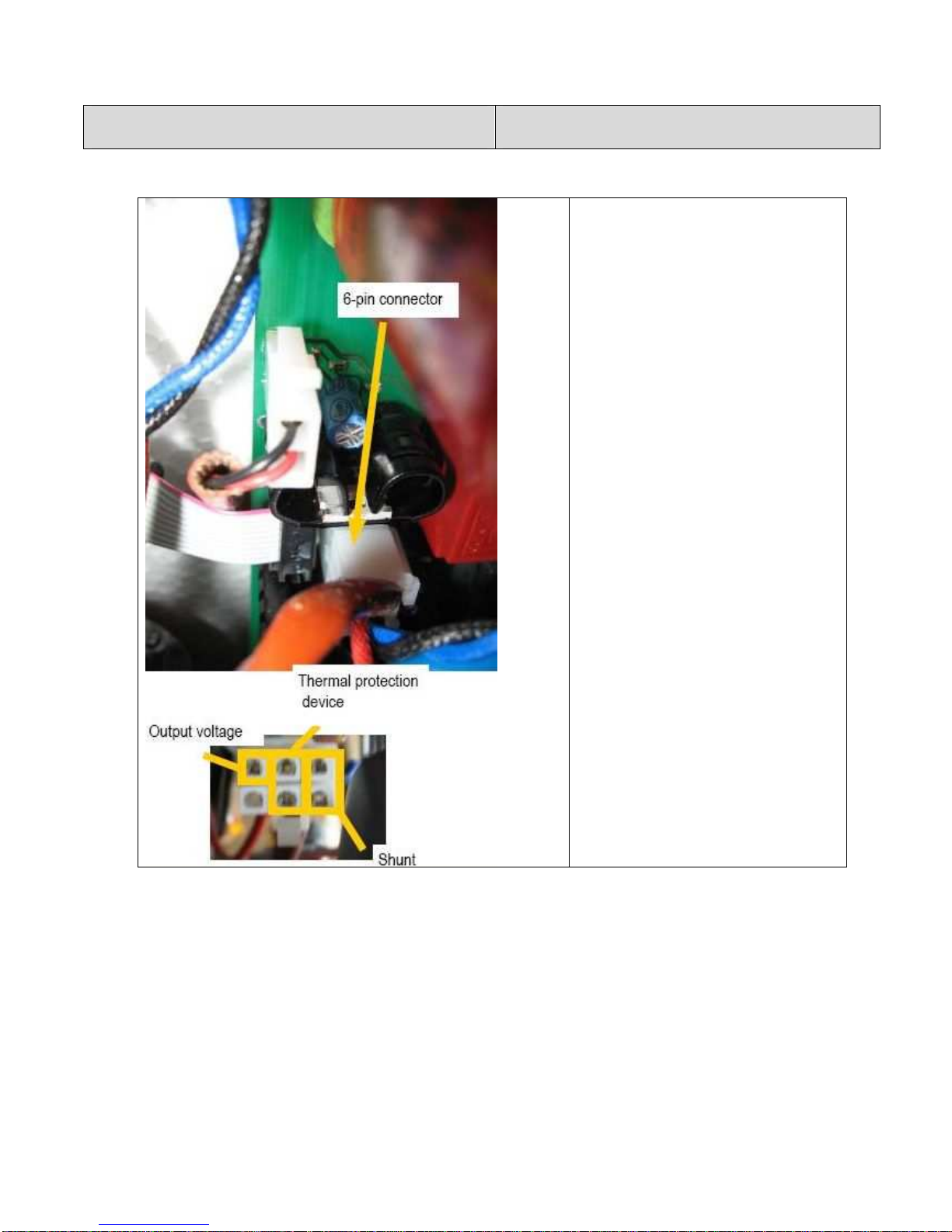
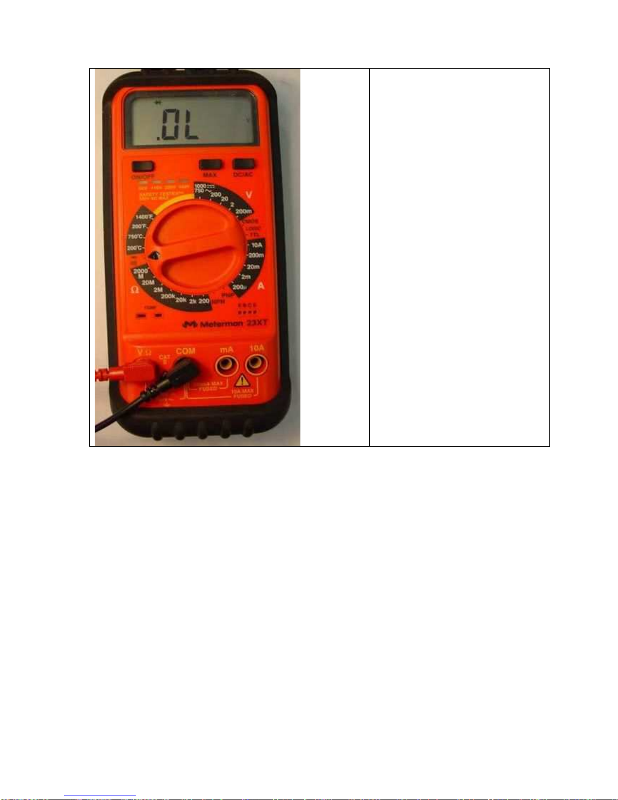
!Switch the machine off and disconnect the
plug. Make sure that when the switch is
closed, there is continuity between the
contact input and output and that the varis-
tor is not broken (picture 4). If it’s dama-
ged, the Power Board must be replaced.
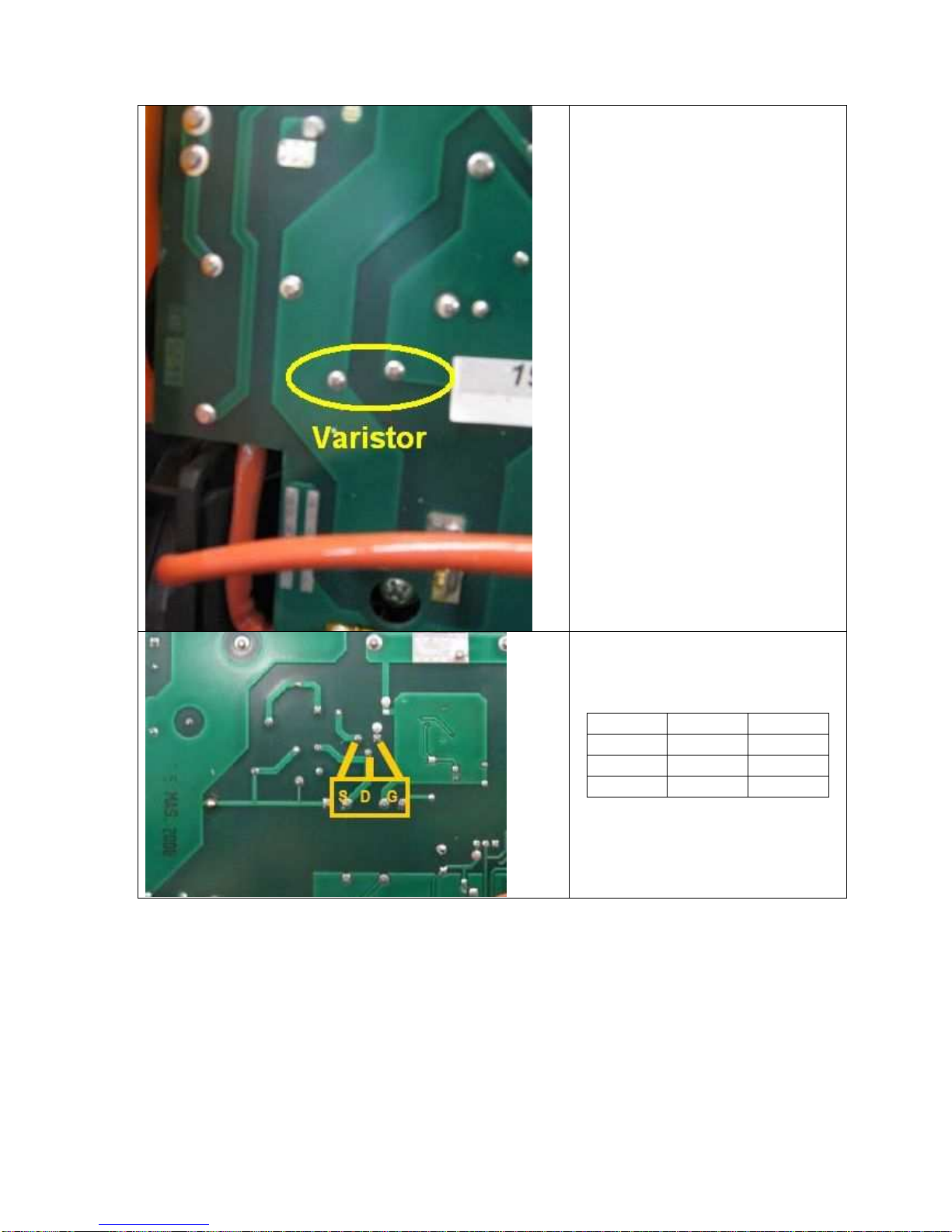
!Switch the machine off and disconnect the
plug. Check the mosfet of the switching
power supply unit on the power board
(picture 5).
The protection devices
of the line set off when
the switch is activated
and the machine does
not go on.
Damaged power supply cable with short-
circuited wires.
Inverter is damaged.
!Switch off the machine and disconnect the
plug. Make sure that there are no short cir-
cuits between the poles of the plug caused
by a damaged power supply cable.
!Switch off the machine, disconnect the
plug and check:
- varistors (picture 4);
- inverter (picture 3);
- Input bridge rectifier (picture 2);
switching power supply unit (picture 5).
If one of these components is damaged
replace the power board.
The front panel does
not switch on.
The fan works but the front panel does
not go on.
Both the fan and the front panel do not
work.
!Switch off the machine and disconnect the
plug. Make sure the flat cable that con-
nects the front panel to the power board is
inserted correctly. If correctly inserted, re-
place the front panel. If the front panel
does not go on, one of the switching power
supply unit outputs is broken. Therefore
the power board must be replaced.
!Switch off the machine, disconnect the
plug and check the mosfet of the switching
power supply unit (picture 5).
!"#$%&'(
)*+,-*( ./--0123( ,45( /20( 6,-7( ,2( 58*( 9/.812*(
9/7*( :4-*(15(1:( ,++(/2;(58*(<=43( 8/:( >**2(;1:?
.,22*.5*;@(
'(