ARDETEM PECA 30 Instruction sheet

ARDETEM ®
ARDETEM Route de Brindas
Parc d’activités d’Arbora
69510 SOUCIEU EN JARREST
France tel : 04 72 31 31 30
fax : 04 72 31 31 31
International tel : 33 4 72 31 31 30
fax : 33 4 72 31 31 31
PECA 30 / 30E
Configuration
manual
Measurement of alternating signals
Single-phase network
3-phase balanced network
3-phase unbalanced network 3 wires
3-phase unbalanced network 4 wires
User’s handbook version : V23-D
Wri
t
in
g
:
C
h
ec
kin
g
: D
ate
:
0
1
/
1
0/0
1


Doc. 97111-CA-G
PECA 30 / 30 E
3
Signal Analyser for Electrical Networks
All types of network :
Single phase, 3-phase balanced, unbalanced, with or without neutral
♦ True effective measure values
♦ Can display 3 parameters simultaneously
♦ Display of 12 parameters : 4 pages
♦ The units are displayed on the front panel
♦ Housing size : 96 x 96 mm
Voltage, Current, Power, Energy, Frequency, COSϕ, etc.

Doc. 97111-CA-G
PECA 30 / 30 E
4
Signal analyser for electrical networks
DESCRIPTION
The PECA 30 analyser by ARDETEM is designed to measure, monitor and control all the parameters in an
electrical network.
The system consists of a rack-mounted compact housing comprising the following functions as selected :
Digital indication with 4 pages of measures
RS485 and RS422 digital output : Modbus-Jbus
Options
Relay outputs
Analog outputs
Pulse outputs
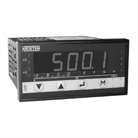
The PECA30 analyser front panel comprises three 9mm extra bright digital indicators.
A scroll system provides a 4-page display.
Display of 12 parameters among a list of 44.
The units of all parameters are displayed on the front panel.
This equipment can be used on all types of networks :
Single phase
3-phase balanced, with neutral
3-phase balanced, without neutral
3-phase unbalanced, with neutral
3-phase unbalanced, without neutral, with or without current leak
With or without current measuring transformer
With or without voltage measuring transformer
It is entirely programmable by means of keys on the front panel.
Programming in clear language, with the possibility of visualising the complete configuration.
A detailed instruction leaflet is provided.
Identification labels corresponding to the standard variables and their respective units are provided, along with
blank labels.
All data programmed by the operator is stored in a non-volatile memory and is thus saved in case of auxiliary
power supply failure.
ADVANTAGES
Compact
Multi-purpose, adapts to all types of network
Entirely keyboard-programmable display of 4 pages of 3 measured parameters
Extra bright display
4-quadrant power mesurement
True effective measure values
Accuracy rating 0.5
Programmable digital filter
Security keys
Digital output RS 485 Modbus-Jbus
Outputs relay, analog, pulse (optional)
Universal power supply

Doc. 97111-CA-G
PECA 30 / 30 E
5
General data
Housing Polycarbonate, black
Format 96 x 96 , DIN 43700 standard
Mounting Rack-mounted, requires 92 x 92 cut-out
Attachment By brackets
Protection IP 20 for housing - IP 40 frontal protection
Connection On rear face
2.5mm² capacity screw-in terminals for current
Indicators 3 x +/- 10 000 count indicators, extra bright digits, 9mm high
Parameter identification 12 unit and symbol labels
Programming By means of keys on front panel
Detailed instructions provided
Electrical data
Auxiliary Power Supply
Voltage High voltage version : 90 to 270 Vac or 88 to 350 Vdc
Low voltage version : 20 to 53 Vac or 20 to 75 Vdc
Power draw ac supply : 18VA , dc supply : 8W
Inputs
Voltage 2 programmable ranges Un = 150 or 500 Vac
Current In = 1 A or 5 A to be specified on order
Measure overload 1.5 In ; 1.2 Un
Electrical overload permanent : 750 V , 2 In transient 10s : 1000 V , 10 In
Power consumption voltage : impedance inputs 1 MΩ, current input : < 0,2 VA
Test voltage 2 KV , 50 HZ / 1 mn
Frequency 50 / 60 Hz – 400Hz available on request
Network type single phase, 3-phase balanced or unbalanced with or without neutral
Measurements
Number of parameters 44
Accuracy rating 0,5 for U, I and P ; 1 for energies (PECA 30 E)
Measurement method 3 currents and 3 voltages simultaneous sampling
32 bits digital computation
Display refreshing 3 per second
Digital filtering 5 keyboard-programmable integration levels
Energy backed-up , reading wtih 8 digits
Cycle time 350 ms 3-phase unbalanced network,
180 ms 3-phase balanced network.
Test conditions
Operating temperatures 0 to +55 °C conform IEC60068-2-1 and IEC60068-2-2
Storage temeratures -25 to +70 °C conform IEC60068-2-1 and IEC60068-2-2
Operating humidity 40°C and 93% no condensation, 10 days : IEC60068-2-30
Vibrations 1,5mm or 2g from 10 to 150Hz conform IEC60068-2-6
Applicable standard IEC 61000-4-2 : level 3 or 6KV contact, 8KV air
IEC 61000-4-3 : level 3 or10V/m from 80MHz to 1GHz with
Amplitude modulation 1KHz at 80%
IEC 61000-4-4 : supply level 4 (4KV),
Inputs / outputs level 4
IEC 61000-4-6 : 10Veff from 150KHz to 80MHz
Amplitude modulation 1KHz at 80%
Generic immunity standards : IEC 61000-6-2 emissions : 61000-6-4
Test standard : EN 55011 class A
Conform with the European Directive 89/336 rev. 92/31 : CE marking

Doc. 97111-CA-G
PECA 30 / 30 E
6
The AC signal analyser can be fitted with one optionnal board :
3 relais outputs board or 1 relay output board
Type of contacts : 2 outputs 2 contacts – 1output 1 contact
Switching capacity : 5A - 250V AC
Threshold setting : programmable (0 to 100% of measurement range)
Switching hysteresis : programmable (0 to 200% of threshlod)
Response time : programmable (0 to 25s)
3 pulse outputs board or 1 pulse output board
Type of outputs : relay switching
Count rate : programmable (0 to 10 pulses per second)
Pulse width : programmable (50, 100 or 250 ms)
3 analog outputs board or 1 analog output board
Galvanic insulation : 500V
Output signal : programmable : -20/20mA -10/10mA -5/5mA 0/5mA
0/10mA 0/20mA 4/20mA
Scale setting : programmable (0 to 100% of measurement range)
Permissible load : < 600Ω(20 mA)
Output resolution : 12 bits
Accuracy : <0,1% full scale for -20/20mA output (in relation to the display)
Output wave : +/-2,5mV on 50Ωload
Response time : 30 ms
Dual output board - 3 analog / 2 relay
See 3 analog otuputs board
Type of contacts : 2 outputs 1 contact
Switching capacity : 2A - 125V Ac
Threshold setting : programmable (0 to 100% of measurement range)
Switching hysteresis : programmable (0 to 200% of threshlod)
Response time : programable (0 to 25s)
Dual output board - 3 analog / 2 pulses
See 3 analog otuputs board
Type of outputs : relay switching
Count rate : programmable (0 to 10 pulses per second)
Pulse width : programmable (50, 100 or 250 ms
4 logic inputs board
Input signal : 0 / 24 V (other on request)
Impedance input : 3,3kΩ/ galvanic insulation : 500v

Doc. 97111-CA-G
PECA 30 / 30 E
7
Dimensions in mm
96 164
90
96
170
89
92
92 Cut-out
Subject to change
Dealer
ARDETEM, Route de Brindas, P.A. d’Arbora, 69510 Soucieu en Jarrest - France
Tél. 33 4 72 31 31 30 - Fax. 33 4 72 31 31 31
RCS Lyon B444 429 476
A
RDETEM

PECA30 / 30 E : general presentation
8
ARDETEM
TABLE OF CONTENTS
CHAP 1 - GENERAL PRESENTATION
ANALYSER RECEIPT P.9
STARTING P.9
PECA SUMMARY P.10
MEASURABLE PARAMETERS LIST P.13
DETAILS OF SOME MEASURED PARAMETERS P.15
CAPTURE FUNCTIONS P.16
CHAP 2 - PROGRAMMING - CONFIGURATION
MAINMENU P.17
MAIN MENU OF CONFIGURATION P.18
CONFIGURATION OF MEASURED NETWORK P.19
CONFIGURATION OF THE DISPLAY P.21
CONFIGURATION OF OPTIONAL BOARDS P.24
CHAP 3 - ACCESSIBLE FUNCTIONS DURING THE MEASUREMENT
SETTING OF UNIT AND SYMBOL LABELS P.36
VISUALIZATION OF THE ENERGIES ON 8 DIGITS P.37
VISUALISATION OF THE MEASURED PARAMETERS Nr AND THE HARMONICS P.38
CURRENT CUT-OFF CALIBRATION P.39
VISUALIZATION OF THE CONFIGURATION P.40
RESETTING OF ENERGIES AND DIFFERENT SETTING P.41
ALARMS AND ERRORS MEASUREMENT P.43
ANALYSER CYCLE TIME P.43
CHAP 4 - WIRING SCHEMA
WIRING ADVICE P.44
AUXILIARY SUPPLY WIRING P.44
SINGLE PHASE NETWORK WIRING : NETWORK Nr1 P.45
3-PHASE BALANCED NETWORK WIRING : NETWORK Nr2 P.46
3-PHASE UNBALANCED WITHOUT NEUTRAL NETWORK WIRING
WITHOUT CURRENT LEAK : NETWORK Nr3 P.47
3-PHASE UNBALANCED WITHOUT NEUTRAL NETWORK WIRING
WITH MEASUREMENT OF THE 3 CURRENTS : NETWORK Nr5 P.48
3-PHASE UNBALANCED WITH NEUTRAL NETWORK WIRING: NETWORK Nr4 P.49
RS 485 DIGITAL OUTPUT WIRING P.50
LOGICINPUTWIRING P.51
EXPANSION BOARDS WIRING P.52

PECA30 / 30 E : general presentation
9
ARDETEM
CHAP 1 – GENERAL PRESENTATION
ANALYSER RECEIPT
Each alternating signals analyser is delivered with :
Its calibration form
this user manual
a Modbus / Jbus manual
2 stickers boards (for measurement units & symbols)
a documentation and a software for the data storage (in option)
a programming and visualization software of the measurements (in option)
Check if the analyser configuration (label on the housing top) corresponds to the order
Dismantle the metallic fixings on the sides
Insert the analyser in the cut-out, then put back the fixings and screw it.
STARTING
Connect the auxiliary supply.
Connect necessarily the earth wire (earth, terminal 12). It’s the guarantee for a good running in case of
electromagnetic disturbances by conduction or radiation.
At the start the analyser displays its type (PECA30, 30E...), and its program version. These data are
necessary for repair services.
Then the analyser displays the measurements with an initial configuration (except a specific order).
It advises strongly to program the analyser before to wire the input network.
Then connect all the signals : the measurement network and the inputs / outputs (refer to the wiring, in
page 44)
Solutions to some faults :
If the analyser isn’t lit : check the auxiliary supply,
check the back fusible
If the analyser doesn’t measure : check the voltage between the terminals 1 and 4 (L1and L4)
check the analyser programming (see page 40)
If the front panel Led « Ctrl » is lit : a wiring or programming mistake has been done.
(see the details page 43)
If the CT are reversed : the P and Q signs are reversed, a rectification is possible (page 19)
If the digital output doesn’t work, some helps are available (see in the Modbus manual)
The wiring of the inputs / outputs screening must be connected as shorter as possible to the terminal 12.

PECA30 / 30 E : general presentation
10
ARDETEM
PECA SUMMARY
The front panel possibilities are:
Wiring or RS RS page displayed
programming transmission reception indication
error
measurement measurement units Keyboard with the functions bellow :
display and symbols
8 Digits energy visualization (page 37)
Harmonics and displayed parameter numbers (page 38)
Page scrolling
Main menu access and errors visualization

PECA30 / 30 E : general presentation
11
ARDETEM
Quick functions summary of menu uses :
Measurement cycle
codE visualization of the configuration : to scroll READING OF THE
8.888 to visualize CONFIGURATION
CLr.E
rEAd CLr.C CLr p 41
CLr codE CLr.H YES
conF 3.333 CLr.m SETTINGS AND
EnEr p42 RESETTINGS
hour p 43
RES SEnS COS COS p 19
n°4 rEC. ELEC. Sor.
n° YES -1.1
CAL CAL p19 NETWORK
rAP 150V PROGRAMMING
P tC S tC P tP S tP p20
rES
codE AFF PAGE PAGE PAGE PAGE p21
1.111 brd n°1 n°2 n°3 n°4
PAGE FIL. p 23
F.numnum. DISPLAY
dISP.n°3 PROGRAMMING
ALAr. Hour AFF. PAGE p 23
ondEC.UOFFScrL
YES OFF
(carte1) (alarm output)
brd.1 PArA HYS SECU dEL SP1 SP2 p 25
ALAr
Sor.1
brd.1 (carte2) (pulse output)
brd.2 brd.2 PArA Acc dEL p 28 INPUTS / OUTPUTS
JbUSPULS PROGRAMMING
Sor.1 (current output)
PArA I mA P dS P FS SECU p 31
JBUS JBUS JBUS JBUS SAVE
ESCL bAUd rEEL PAr. YES p 34
1 9600 YES EVEn
Keys operating :
to scroll. to valid. back to the measurement.
Auto measurement return after 1min 30s without key handling.

PECA30 / 30 E : general presentation
12
ARDETEM
DISPLAYED ABBREVIATIONS LIST ON THE DIFFERENT MENUS :
Acc : increase in energy witch provides a pulse
AFF : display programming
AFF. OFF : auto extinguishing of the display, after 5 min.
AnA : 3 analog outputs board (current)
ANA.A : 3 analog outputs (current) + 2 alarm outputs mixed board
ANA.P : 3 analog outputs (current) + 2 pulse outputs mixed board
bAUd : transmission speed (for the serial interface) (baud rate)
brd : optional board
CAL : voltage calibre
CAL Urn : simple voltage calibre (for the network Nr: 4)
CAL UrS : mesh voltage calibre (for the network Nr: 2,3 et 5)
CALC : message displayed during the harmonic calculation
CLr : reset
CLr.E : energies reset
CLr.C : (current, power…) peak value reset,
CLr.H : running time-meter reset
CLr.m : measurement time saving reset
conF : all PECA configuration
dEC.U (dEC.I) : running time-meter set of the UTR or IR presence
dEL : threshold relay commutation delay or pulse time delay
dISP : functions about the display (alarms display, automatic extinguishing,…)
EA.O1 (EA.O2) : active energy out meter 1 : normal ( meter 2 : ex: for EJP )
EA.I1 (EA.I2) : active energy in meter 1 : normal ( meter 2 : ex: for EJP )
ELEC : electrical cosinus (YES) or mathematical (no)
EnEr : energies setting, or capture value from the front key of the PECA
Er.O1 (Er.O2) : reactive energy out meter 1 : normal ( meter 2 : ex: for EJP )
Er.I1 (Er.I2) : reactive energy in meter 1 : normal ( meter 2 : ex: for EJP )
Err : configuration, wiring ...errors visualization
ESCL : Modbus/Jbus slave number for the serial interface
F. num. : measurement logic filtering
FIL.num : total measurement filtering
FIL.PIC : peaks elimination
HAr.U (HAr.C) : Utr voltage harmonic (Ir current)
HI (LO) : high saturation (HIgh) or low saturation (LOW)
hour : time-meter setting
HYS : threshold relay hysteresis
I mA : current output scale in mA
JBUS : Modbus / Jbus optional board
PArA : measurement parameter number (see page 13)
P dS ( P FS ) : Parameter down and Full Scale
PULS : 3 pulse outputs board
P tC ( P tP ) : primaries of the current, voltage external transformer
rAP : external current, voltage transformer ratio
rEAd : PECA configuration (programming) reading
rEC. (gEN.) : network current sense, the load is receiver (generator) of current
rEEL : pattern Modbus transmission in real (floating decimal point) or double integer
rES : measured network (rES Nr..:= network type)
SAVE : captured configuration saving
ScrL : auto scrolling of the pages (scroll)
S tC ( S tP ) : secondaries of the current, voltage external transformer
SECU : threshold relay security or output current saturation in case of alarm
SEnS : current sense (the load is generator or receiver of current)
Sor.1 : Nr 1 output (optional board)
SP 1 ( SP 2 ) : relay threshold 1 (threshold 2 )

PECA30 / 30 E : general presentation
13
ARDETEM
MEASURABLE PARAMETERS LIST
network nr
30 30E Nr MEASURED PARAMETERS 1 2 3 4 5
X X 1 UTR (mesh voltage) X X X X X
X X 2 URS (mesh voltage) X X X
X X 3 UST (mesh voltage) X X X
X X 4 Umean = (UTR+URS+UST) / 3 X X X
X X 5 VR (single voltage phase R) X
X X 6 VS (single voltage phase S) X
X X 7 VT (single voltage phase T) X
X X 8 IR (line current phase R) X X X X X
X X 9 IS (line current phase S) X X X
X X 10 IT (line current phase T) X X X
X X 11 Imean = (IR+IS+IT) / 3 X X X
X X 12 Leak current In X X
X X 13 IR max (on N minutes*) X X X X X
X X 14 IS max (on N minutes*) X X X
X X 15 IT max (on N minutes*) X X X
X X 16 COS total X X X X X
X X 17 Frequency X X X X X
X X 18 Impedance X X X X X
X X 19 Total active power X X X X X
X X 20 Total reactive power X X X X X
X X 21 Total apparent power X X X X X
X 22 Mean active power (on N minutes*) X X X X X
X 23 Mean reactive power (on N minutes*) X X X X X
X 24 Active energy OUT X X X X X
X 25 Active energy IN X X X X X
X 26 Reactive energy OUT X X X X X
X 27 Reactive energy IN X X X X X
X 28 Active energy OUT, meter 2 X X X X X
X 29 Active energy IN, meter 2 X X X X X
X 30 Reactive energy OUT, meter 2 X X X X X
X 31 Reactive energy IN, meter 2 X X X X X
X X 32 COS, phase R X
X X 33 COS, phase S X
X X 34 COS, phase T X
X X 35 Active power, phase R X
X X 36 Active power, phase S X
X X 37 Active power, phase T X
X X 38 Reactive power, phase R X
X X 39 Reactive power, phase S X
X X 40 Reactive power, phase T X
41 Analog DC input Nr 1 X X X X X
42 Analog DC input Nr 2 X X X X X
43 Analog DC input Nr 3 X X X X X
X X 44 Running time counter X X X X X
* N minutes = average value on the N last minutes ( N programmable : 1 up to 60mn)

PECA30 / 30 E : general presentation
14
ARDETEM
Optional parameters : NOT AVAILABLE ON PECA 30 / 30 E
network nr
Nr MEASURED PARAMETERS 1 2 3 4 5
45 Year X X X X X
46 Day, Month X X X X X
47 Hours, Minutes X X X X X
48 Voltage distortion rate X X X X X
49 Current distortion rate X X X X X
50 Samples dots number X X X X X
51 Filling ratio of the saving memory (%) X X X X X
52 UTR harmonic 2 X X X X X
53 UTR harmonic 3 X X X X X
... X X X X X
60 UTR harmonic 10 X X X X X
61 UTR harmonic 11 X X X X X
... X X X X X
70 UTR harmonic 20 X X X X X
71 non used X X X X X
72 IR harmonic 2 X X X X X
73 IR harmonic 3 X X X X X
... X X X X X
80 IR harmonic 10 X X X X X
81 IR harmonic 11 X X X X X
... X X X X X
90 IR harmonic 20 X X X X X
Network 1 = single phase
Network 2 = 3-phase balanced
Network 3 = 3-phase unbalanced without neutral & without leak current ( IR+IS+IT=0 )
Network 4 = 3-phase unbalanced with neutral
Network 5 = 3-phase unbalanced without neutral, measurement of the 3 currents IR, IS, IT & In leak.
The impedance and the harmonics are calculated on the R phase.
The harmonic distortion rate is calculated like below :
Y2²+Y3²+...+Y30²
THD = 100 x Yn is the harmonic range of the rank n
Y1
= H2²+H3²+...+H30² Hn is the % rate of the n harmonic (Hn display value)
The measured parameters are programmed on the indicators like below : (details page 21)
Standard parameters :
Parameter Nr display unitdecimal point position
Max. current and average power on N minutes :
Parameter Nr N minutes (10, 15mn...) display unit decimal point position
Analog DC inputs:
Parameter Nr display down scaledisplay full scale decimal point position

PECA30 / 30 E : general presentation
15
ARDETEM
The PECA displays P >0
The PECA displays Q >0
DETAILS OF SOME MEASURED PARAMETERS
SIGNIFICATION OF THE DIFFERENT ENERGY METER :
PROGRAMMING IN RECEIVER MODE (see page 19)
Q+
Active energy IN Active energy OUT
reactive energy OUT P- Q+ P+ Q+ reactive energy OUT
capacitive inductive
generator engine
The choice between an electrical
elec. cos <0 elec. cos >0 or mathematical COS is
P- math cos <0 math cos >0 P+ programmable (see page 19)
elec. cos >0 elec. cos <0
math cos <0 math cos >0
inductive capacitive
generator engine
Active energy IN P- Q- P+ Q- Active energy OUT
reactive energy IN reactive energy IN
Q-
PROGRAMMING IN GENERATOR MODE (see page 19)
Q+
Active energy IN Active energy OUT
Reactive energy OUT P- Q+ P+ Q+ reactive energy OUT
capacitive inductive
engine generator
The choice between an electrical
elec. cos <0 elec. cos >0 or mathematical COS is
P- math cos <0 math cos >0 P+ is programmable (see page 19)
elec. cos >0 elec. cos <0
math cos <0 math cos >0
inductive capacitive
engine generator
Active energy IN P- Q- P+ Q- Active energy OUT
Reactive energy IN reactive energy IN
Q-
• MEAN POWER :
The analyser calculates the chosen mean power, for a programmable duration (10mn,15mn...) It’s possible for
the active and reactive power. The mean value is automatically updated according to the programmable
duration.
• RUNNING TIME-METER:
We can get the installation running time thanks to the running time-meter which increase itself while that UTR
is measurable or IR, choice to make by programming (page 23)
The value is displayed on the pattern : Hours, Tenth hours, Hundredth hours...
CAUTION :
Maximum value : 2000GWh
Next the energy meter starts from zero.

PECA30 / 30 E : general presentation
16
ARDETEM
• TIME METER DATE AND TIME : NOT AVAILABLE ON PECA 30 / 30 E
We have in option a time-meter function, which is supplied with the measurement data storage option.
PATTERN EXAMPLE : the 9th may 1997 it is 9h45min
Display configured with 3 numbers after the decimal point : Year = 1997.0 Day, Month = 9.050
Hour = 9.450
A display without decimal point for the year and 2 decimals for the day and the hour will give a readable
display : Year = 1997 Day, Month = 9.05 Hour = 9.45
• MAXIMUM OF THE CURRENTS :
The analyser displays the maximum of the currents on the last N minutes (N is programmable
ex :10 minutes) (average value calculated on the last N minutes).
The duration N is common with the integration duration of the mean powers.
CAPTURE FUNCTIONS
Nr1 - 4 DIGITS NUMBER WITH SIGNE AND DECIMAL POINT :
4th digit + sign, from –9 to +9
3rd digit from 0 to 9
2nd digit from 0 to 9
1st digit from 0 to 9
decimal point

PECA 30 / 30 E : programming-configuration
17
ARDETEM
CHAP 2 - PROGRAMMING - CONFIGURATION
MAIN MENU
By pressing the key during the measurement, it gives you access at the general menu
Display during 2s : the analyser version and its program version.
01
display during 4s : the error number signalled by the blinking during the
measurements of the Led « ctrl » in front panel (details page 43)
N=1 : RS wiring error N=2 : incorrect currents order
N=3 : incorrect phases order N=4 : current over-range
N=5 : voltage over-range N=6 : frequency over-range (F<45 or F>65Hz)
N=7 : programming loss N=8 : calibration loss
access to the 3 functions of general menu
Complete -RESET of energies Complete
analyser -RESET of max. currents analyser
configuration -RESET of running time-meter configuration.
reading. -Energies setting
-Time-meter setting
-RESET of the data saving memory.
PAGE 40 PAGE 41 PAGE 18
See capture fonction Nr 1 page 16
V
01
PECA
30
N
Er
r
n°
conF
rEAd
CL
r
codE
3.333
codE
1.111

PECA 30 / 30 E : programming-configuration
18
ARDETEM
MAIN MENU OF CONFIGURATION
This menu allows to configure the 3 main menu functions of the analyser :
Measured network Display Optional boards
configuration configuration configuration
(nr, calibre ...) (parameters, units...) (inputs / outputs)
PAGE 19 PAGE 21 PAGE 24
By pressing the key, from each step, the programming can be interrupted with or without saving.
brd
rES
AFF

PECA 30 / 30 E : programming-configuration
19
ARDETEM
CONFIGURATION OF MEASURED NETWORK
Access from the measurement cycle : conF codE=1.111 rES
Example : 3-phase unbalanced network with neutral, calibre 230V, CT ratio : 1500/5A , VT : 12KV/110V
Network type Nr 1 to 5
Network type choice : 1=single phase 2=3-phase balanced
3=3-phase unbalanced without neutral (3 wires) without current leak
4=3-phase unbalanced with neutral (4 wires)
5=3-phase unbalanced without neutral (3 w.), leak current measurement
Choice of current sense : receiving or generating
load of current (it modifies the P & Q sign).
Power factor (cosinus)
electric « YES » or mathematical « no ».
See the explains page 15 and 31
COS analog output
adjusted on +/-1 or 0
(details page 31)
Voltage calibre
Choice of the voltage calibre : 2 calibres : 500V or 150V
CAUTION : simple voltage calibre for the network Nr 4
mesh voltage calibre for the network Nr 2,3 and 5.
See the next page
back to the main menu back to the measurement.
rAP
n°
CAL
rES
n°4
SEnS
REC.
SEnS
g
En.
no
COS
ELEC.
YE
S
COS
ELEC.
rAP
n°
CAL
150U
CAL
Urn
-1.1
COS
Sor.
0
COS
Sor.

PECA 30 / 30 E : programming-configuration
20
ARDETEM
CT and VT ratio
( without CT nor VT, capture for the primary and the secondary,
a value of 1.000 with 1 for unit)
capture the CT primary value
1500.
capture the CT primary unit
1, 10 3=kilo, 10 6=mega, 10 9=giga
capture the CT secondary value
capture the CT secondary unit
1, 10 3=kilo, 10 6=mega, 10 9=giga
capture the VT primary value
capture the VT primary unit
1, 10 3=kilo, 10 6=mega, 10 9=giga
capture the VT secondary value
capture the VT secondary unit
1, 10 3=kilo, 10 6=mega, 10 9=giga
configuration of the display on the next page
See capture function Nr1 page 16 back to the main menu back to the measurement
1500.
P tC
1
P tC
5.000
S tC
1
S tC
12.00
P tP
10 3
P tP
110.0
S tP
1
S tP
rAP
n°
CAL
This manual suits for next models
1
Table of contents
Other ARDETEM Measuring Instrument manuals
Popular Measuring Instrument manuals by other brands

BRUEL & KJAER
BRUEL & KJAER 2204 Instructions and applications

SENTRON
SENTRON ISFET Full manual

OWL
OWL Micro OWL 2 Series Testing

PCB Piezotronics
PCB Piezotronics 353B04 Installation and operating manual

MAHA
MAHA POWERDYNO MSR Series Original operating instructions

turck
turck IM34-11Ex-i quick start guide