ARDETEM DIP 10 Instruction Manual

ÉTUDES ET RÉALISATIONS
ÉLECTRONIQUES / INSTRUMENTATIONS / AUTOMATISME
Route de Brindas - Parc d’activité d’Arbora - N°2
69510 - Soucieu en Jarrest
Tél. 04 72 31 31 30 - Fax 04 72 31 31 31
Tel. Intern. 33 4 72 31 31 30 - Fax Intern. 33 4 72 31 31 31
ARDETEM - TA IN/46 - C 11/06 - Any data in this documentation may be modified without prior notice.
ARDETEM
Soucieu en Jarrest - FRANCE
http: //www.ardetem.com - e-mail: [email protected]
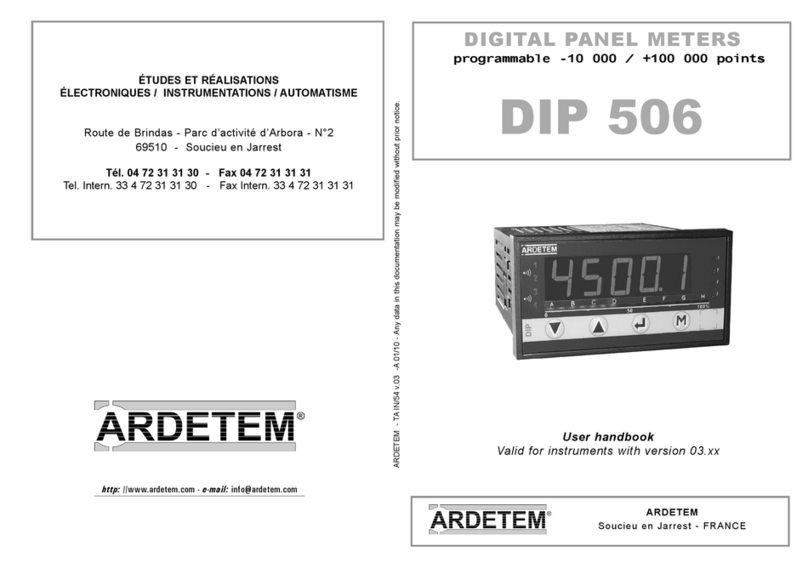
DIGITAL PANEL METER
programmable ±10 000 points
User handbook
Valid for instruments with version 01.xx
DIP 10

p1
1 . INTRODUCTION p2
2 . SPACE REQUIREMENTS p3
3 . CONNECTINGS p4
4 . PROGRAMMING p5
4.1 Communication with the instrument p5
4.2 Orientation through the programming p5
4.3 Main menu p5
4.4 Programming menu p6
4.4.1 - Programming of the input p6
a / Process signals p6
b / Temperature signals p7
c / Resistive sensors p7
4.4.2 - Programming of the display factor p8
4.4.3 - Programming of the analog output p8
4.4.4 - Programming of the relay outputs p9
4.4.5 - Programming of the safeties p9
4.4.6 - Programming of the display p10
4.5 Features of the inputs and programming limits p10
4.5.1 - Current and voltage input p10
4.6 Features of the outputs and programming limits p11
4.6.1 - Analog output p11
4.6.2 - Relay outputs p12
4.6.3 - Safeties p13
4.6.4 - Display features p14
4.7 Reading of the configuration p14
4.8 Access code p15
4.9 Programming of a new access code p15
4.10 - Functions of the the main menu p15
4.10.1 - Display simulation p15
4.10.2 - Simulation of the analog output p16
4.10.3 - Menu CLEAr :
Deleting of the recorded alarms p16
4.10.4 - Menu CLr.tA:
Suppressing of the programmed tare p16
5 . FUNCTIONS WHICH CAN BE REACHED FROM
THE FRONT FACE p17
5.1 Functions which require pressing only 1 key p17
a / Display of the minimum value p17
b / Display of the maximum value p17
c / Deleting of the min. and max. values p17
5.2 Functions which require pressing several keys p17
5.2.1 - Shifting of the display p17
5.2.2 - Visualisation of the direct measure p18
5.2.3 - Visualisation and setting of the alarm setpoints p18
5.2.4 - Setting of the tare (process input only) p18
6 . ERROR MESSAGES p19
7 . GENERAL WARRANTY TERMS p19
8 . LEXIQUE p19

p2
The DIP 10 is a high accuracy digital panel meter. It is equipped on front
face with a four 14 mm high red digits display, whose brightness suits
applications in industrial control rooms perfectly.
It allows the display, the control and the transmission of data from any
measurable magnitudes.
AVAILABLE OPTIONS: (specify on order)
Insulate analog output: A
Active current output, or voltage.
Programmable scale ratio with enlarging effect.
Relay output:R
2 relays: mode setpoint or window.
Recording of the alarms.
Time delay and hysteresis adjustable on each setpoint.
Alarm messages
CODING:
• Type: DIP 10
• Output options:
A: Analog (A1 or A3: specify)
R: 2 relays
These options can be combined simultaneously
Order example:
For a panel meter with 1 active current analog output and 2 relays,
request reference DIP 10 A1R
1. INTRODUCTION Features of the inputs
♠ A 12 µA pulsed current
allows the detection of line or
sensor rupture
Thermic drift <150ppm /°C
(1) Line resistance <25Ω
(2) Or 30 µV typical (60µV Max.)
♦ CJC efficiency: ±0.03°C/°C
±0.5°C
from -5°C to +55°C
MR Measure range
♣ Cut off : the display and the
output remain at down scale for
an input signal < value of the cut
off, programmable from 0% to
100% of the input range.
Types of
INPUTS
Measure range adjustable
from
Permanent
overload
Intrinsic
error
Input
impedance
mA♣
-2 to +22mA
±100mA
<
±0.05%
of the MR
Max. drop
0.9V
mV
♠♣ -10 to +110mV ±1V
≥ 1MΩ
V
♣
-0.1 to +1.1 V ±50V
-1 to +11V
-30 to +330V ±600V
Thermocouples ♠
Standard IEC 581
J
K
B
R
S
T
E
N
L
W
W3
WRE5
°C
-160/1200
-270/1370
200/1820
-50/1770
-50/1770
-270/410
-120/1000
0/1300
-150/910
1000/2300
0/2480
0/2300
°F
-256/2192
-454/2498
392/3308
-58/3218
-58/3218
-454/770
-184/1832
-32/2372
-238/1670
1832/4172
32/4496
32/4172 -
♦(2)
<±0.1%
of the MR
≥ 1 MΩ
Sensor Pt100Ω (1)
♠
3 wire, Standard
IEC 751 (DIN 43760)
°C
-200/850
°F
-328/1562
-<±0.1%
of the MR
Current
250µA
Sensor Ni 100 3 fils (1)
♠
-60/260 -76/500 -
Resistive sensors Calibers 0-440 Ω and
0-2.2 kΩ ♣
(0-8.8 kΩ optional)
<±0.1%
of the MR
(0.5% for
0-2KΩ)
-
Potentiometer
from 100Ω to 10 kΩ ♣
Supply for 2 or 3-wire
sensor
24 VDC ±15% with protection from
short-circuits. 25 mA max.
Special linearisation
programming up to
20 points
On input: mV, V, mA.
Resistive sensors and potentiometer

p3
Protection:
Front face: IP 65
Housing: IP20
Terminals: IP 20
Housing:
Self-extinguishing case of
black UL 94 V0 ABS.
2. SPACE REQUIREMENTS
Dimensions of the case: (with terminals)
96 x 48 x 124 mm
Mounting on panel
cut out 44 x 91 mm
external
seal
Mounting panel
max. thickness 30
case
tightenings
terminals
Plug off connectors on rear face for
screwed connectings (2.5mm², flexible
or rigid)
Display: ±10 000 points (14 mm)
Electroluminescent red (green optional)
2 alarm leds
Features of the outputs
Types of
OUTPUTS
1 analog insulated
Active
current
or Voltage
A1
2 inverting relays
R
Current: direct or reversed 0-20mA
Load impedance ≤ Lr 600Ω
Voltage: direct or reversed 0-10V
Load impedance ≥ Lr 500kΩ
2 setpoints per relay
configurable on the whole MR.
Hysteresis programmable from 0 to 100%.
Time delay programmable from 0 to 25 sec.
(8A/250 VAC on resistive load)
Features
Code
A3
General features
Galvanic partition:
2.5 kV eff. - 50 Hz - 1 min between supply, inputs, outputs
• Standard sampling time: 100 ms
• Common mode rejection rate: 130 dB
Serial mode rejection rate: 40 dB 50/60 Hz
• Zero drift compensation and self-calibration
• Conform with standards IEC 61000-6-4 on rejections and IEC 61000-6-2 immunity
(in industrial environment) IEC 61000-4-2 level 3, IEC 61000-4-3 level 3,
IEC 61000-4-4 level 4, IEC 61000-4-6 level 3.
CE marking according to the directive EMC 89-336.
20 to 270 VAC - 50/60/400 Hz and
20 to 300 VDC
Max. operating range
3 W max.
5.5 VA max.
Power draw
Power supply:

A
p4
3. CONNECTINGS
Location of the terminals
(view of case rear face)
1 2 3 4 5 6 7 8 9 10 11 12 13 14 15 16
A
3 4 5678
INPUTS
300V
1V
10V
mV
mA
+ -
+ -
+ -
+ -
2-wire transmitter
NC
3-wire transmitter
+
-
VOUT GND VCC
567
Tc
+ -
Pt100 3 wire
Ni 100 3 wire
4567
Potentiometer
RESISTANCE AND POTENTIOMETER
TEMPERATURE
PROCESS
Resistance >440Ω up to 2kΩ
(0-8kΩ optional)
Strap 4 and 7 on terminal
0-440Ω resistance
<
1 2
-
~
~
+
AC
DC
OUTPUTS (options)
POWER SUPPLY
16
15
14
13
12
11
T2
C2
R2
T1
C1
R1
T : ON
C : Common
R : OFF
0-4/20mA
CURRENT
VOLTAGE
+ -
10
9
mA
2 RELAYS:
0-10V
+ -
10
9
V
A
A
A
A
A

p5
4. PROGRAMMING
4.1 Communication with the instrument
Several functions can be reached directly on the front panel:
4.3 Main menu
4.2 Orientation through the programming
The dialogue is ensured by 4 keys located on the front face.
Move through the menus:
downwards, or decrease
the value shown
Validation of the displayed
parameter, or access to a submenu
Exit from a submenu to access
next menu / access to the pro-
gramming exit menu
Note: In mode programming, the istrument will automatically revert to
the measure with the former configuration if no key is pressed during
1min.
Move through the menus:
upwards, or increase the
value shown
Display of
the max.
value p17
0 reset of the
min. and max.
p17
Access to the
main menu p5
If code correct,
access to the
programming
menu
(see p6)
Further functions can be reached by pressing several keys simulta-
neously:
Reading convention:
Move through the main menu
Revert to previous menu
Blinking display: awaiting validation or setting
Alternating information display
Entering of a parameter:
First start by increasing or decreasing
the 1st digit and the sign: from -9 to +9.
the 2nd from 0 to 9.
the 3rd from 0 to 9.
the 4th from 0 to 9.
M
M
Alarms
Led 1
Led 2 Display of the
measure
M
M
+
M
+
M
+
+
and
6888
6588
6528
6520
«
scroll
menus
vertical
move
Between each entering, validate
the cipher with key
Display of
the min.
value p17
If code
incorrect,
message
appears
no
Entering of the access code
The access to the programming
menu is protected by a 4-cipher
code.
On factory exit, the code is 0000
(to change the code, see page
15).
Setting of the display down scale; (see p17)
Setting of the display full scale; (see p17)
Visualisation of the direct measure; (see p18)
Visualisation and setting of the alarm setpoints; (see p18)
Mode reading
of the
configuration
(see p14)
Simulation
of the ana-
log output
(see p16)
Authorized by
access code
Deleting of
the recorded
alarms
(see p16)
rEAd ProG
CodE
8 888
GEnE. CLEAr
«
«
«
«
«
Programming
of the access
code
(see p15)
Simulation of
the display
(see p15)
Authorized by
access code
(relay/analog
outputs)
(analog
output)
(inputs process,
resis., potent.)
(relay output)
P.CodE SIMUL
«
«
0 reset of
the function
TARE
(see p16)
Authorized by
access code
CLr.tA
«

Note:
⇒ In mode programming, the instrument will automatically revert to measure
with the former configuration if no key is pressed during 1min.
p6
InPut
4.4 Programming menu (according to options)
diSPL.
AnA.
rELAY
SECU
Pr.diS
Access to the programming of the input p6
Access to the programming of the display factor p8
Access to the programming of the analog output p8
(option analog output)
Access to the programming of the relays p9
(option relay outputs)
Access to the programming of the outputs, the relays p9
in case of error self-diagnosis and/or sensor
rupture, and access to disconnecting the sensor rupture
(option analog or relay output)
Access to the programming of the display p10
Access to the programming exit menu with p10
or without saving of the configuration
M
Move through the menus / choice
Upwards move / increase
Downwards move /
decrease
Validation / vertical move
Menu exit / access
M
Note:
Press to go on to next menu
SAvE
InPut
4.4.1 Programming of the input
a. Process signals
voltage input
voltage input only
choice of the caliber
to t° sensors
resistive sensors
«
100M
«
«
U
«
InPut
300U1U 10U
current input
«
MA
2.UirE
yES no
«
tyPE
«
CALib
diSPL.
Connection of the mA
sensor:
Choose if a
mA passive sensor
is to be connected
between terminals 5
and 8 (2-wire
transmitters)
YES

p7
b. Temperature signals
temperature inputs
process
signals
temperature signals
process signals
CJC * compensation
external internal
* cold junction com-
pensation, except ther-
mocouple B which is
only in CSF-E (external
CJC)
Available only in the case where a
shifting of the input has been ente-
red (see page 17)
external CJC only
If no shifting
# Changing this parameter requires re-programming
the following parameters related to the relays and the
analog output:
SPxx, hystx, do.diS, Fo.diS
#
If thermocouple
if other than thermocouple
«
CJC-E
«
CJ-t°
«
CJC
«
yES
«
no
«
AdJuS.
«
«
«
«
«
«
«
«
«
«
«
«
to
tc--
diSPL.
tc-S
tc-CAtc-J tc-r tc-t tc-E
tc-b tc-n tc-C tc-C3 tc-C5 tc-L
«
«
oF
oC
«
rES
«
Pot
-10°.0C < CJC < 60°.0C
14°.0F < CJC < 140°F
(2)
(2)
c. Resistive sensors
dISP
InPut
M
diSPL.
Note:
Press to go to menu
Move through the menus / choice
See also the features of the inputs p10
InPut
«
tEMP
«
Pt 100 tc
ni 100
«
«
CAPt.
«
CJC-i
«
«
«
«
-888.8
M
Move through the menus / choice
Upwards move /
increase
Validation / vertical move
M
Downwards move /
decrease
Menu exit / access
Note:
Press to go on to next menu
«
CALib
«
400
«
2000
«
8000
or or
according to option
if resistance

p8
4.4.2 Programming of the display factor
diSPL.
inputs process, resistance, potentiometer
place of the decimal point
«
rESOL.
--.--
display resolution
1 or 1/10th of degree
temperature input
setting in display points (or in input
points if SCALE NO is program-
med) of the same number of ordi-
nates “bxx” and abscisses “Axx”
if SCALE YES :
Y00 = dDIS and YNB-1 = F.DIS
according to options
IntEG: coefficient from 0 to
integration indice
AnA. rELAy SECU
«
0000
or or
«
«
DISP
From 3 to 20 : represents the
number of points (including
the down and full input scale)
Xoo=dinp
XNB-1=F.INP
«
IntEG.
«
«
1o
0.1o
«
Point
«
Funct.
«
Li.SPE
«
LinEA.
«
«
nb
«
function special
linearisation
«
0020
«
-88.88
«
-88.88
«
A19
«
A00
«
-88.88
«
F.in
«
-88.88
«
d.diSP
«
-88.88
(1)
in mV, V or mA
according to the
type
full scale
in mV, V or mA
according to the
type
display corres-
ponding to the
input down scale
«dInp»
«
F.diSP
«
-88.88
display corres-
ponding to the
input full scale
«F.INP»
(1)
-2< x < 22.00 (mA)
-1< x <11.00 (10V)
-30< x < 330.0 (300 V)
-10< x < 110.0 (100mV)
-0.1< x < 1.100 (1V)
(1)
«
d.in
linear function
down scale
b00
«
-88.88
«
Cut.oF
b19
«
-88.88
no
«
«
yES
«
-88.88
(1)
(1)
setting in display points
You can choose to assign the analog output to the input measure (PArA InPut) or to the displayed measure
(PArA diSPL.).
Eg.: with PArA diSPL
• When the transmitter indicates 20°C the value of the analog output will be 4 mA
• When the transmitter indicates 100°C the value of the analog output will be 20 mA
Eg.: with PArA InPut
• When the value of the current measured on the input is 6.0 mA, the value of the analog output will be 4 mA
• When the value of the current measured on the input is 20.0 mA, the value of the analog output will be 20 mA
«
-88.88
AnA
down scale of the analog output
According to the equipped
output type
full scale of the analog output
display corresponding to the output down scale
display corresponding to the output full scale
according to options
rELAy SECU
or
See also the features of the outputs p11
(4)
00.00 < x < 22.00 (mA)
00.00 < x < 11.00 (V)
(4)
(4)
«
-88.88
«
-88.88
«
-88.88
«
d.out
«
F.out
«
FO.diS
«
tyPE
AnA.
«
«
OUt.U OUt.i
«
d.out
«
F.out
«
dO.diS
«
FO.diS
Upwards move / increase
Validation / vertical move
Downwards move /
decrease
Menu exit / access
M
PArA
InPut diSPL.
«
dO.diS
= 4 mA = 20,00mA = 20,0° = 100,0°
InPut = mA
«
d.out= 4 mA
«
F.out
«
dO.diS
«
FO.diS
= 20 mA = 6,0 mA = 20,00 mA
4.4.3 Programming of the analog output (if option)

«
rEL.1
rELAY
«
AL.1
«
On
«
02.00
00.00
«
«
«
000.0
«
02.00
«
04.00
rELAY
hysteresis
0 < hys. < 9999
in display points
0 < tIME < 025.0
in 0.1s increments
function recording of the alarms
function display of an alarm message
enter 4 characters
at the end of menu rEL.2,
access to or
choice of the status of the relay
associated led
ON : led lit when relay active
OFF : led still when relay active
time delay on the relay
SP2.1 must be ≥ SP1.1
active
alarm
idem
REL1
de-activated
mode window
mode setpoint
access to SP1 access to SP1.1
«
OFF
«
On
«
no
«
YES
«
«
no
ABCD
rEL.2 SECU Pr.diS
«
«
«
yES
choice of the relay
operating mode:
mode setpoint or
window
(see page 12)
(5)
(5)
See also the
features of the
relay outputs
p12
«
OFF
if mode window programmed
if mode setpoint programmed
«
rEL2
SECU
Features of the safeties p13
option 2
relays
if input mV or t°
option analog output
if return value programmed
«
«
LO HI
«
OFF
OUt.U
status of the relay 1 in case of sensor rupture
«
LO HI
«
OFF
status of the relay 2 in case
of sensor rupture
disconnection of the sensor rupt.
or
«
yES
«
«
«
no
«
value of the output in case of sensor rupture
00.00<rEPLI<22.00 (mA)
00.00<rEPLI<11.00 (V)
«
OFF
«
On
OFF : sensor rupture inac-
tive on the relay
In case of sensor rupture
LO : relay de-activated
HI : relay active
«
-88.88
option relays
option analog output
if return value programmed
«
LO HI
«
OFF
OUt.I OUt.U
status of the relay 1 in case
of self-diagnosis error
or
«
yES
«
«
«
no
«
rEPLi value of the output in case of error self-diagnosis
00.00<rEPLI<22.00 (mA)
00.00<rEPLI<11.00 (V)
OFF : self-diagnosis
inactive on the relay
In case of error self-
diagnosis
LO : relay de-activated
HI : relay active
«
-88.88
Pr.dIS
«
rUPt.
«
SECU
«
dIAG.
«
«
«
rEL.1
«
«
«
«
LO HI
«
OFF
status of the relay 2 in case of
self-diagnosis error
«
rEL.2
«
p9
If input mV, temperature, resistance
or mA (if dINP and F.INP > 3.5mA)
PAr1
InPUt diSPL
ModE.1
«
MEM.1
«
LEd1
«
SP 1
«
HySt.I
tiME.1
«
SP1.1
«
SP2.1
MESSI
rEL.1
OUt.I
rEPLi
CAPt.
rEL.2
4.4.4 Programming of the relay outputs (if option) 4.4.5 Programming of the safeties

p10
Pr.diS
«
On
«
OFF
«
yES
«
no
1 1 1 1
setting of the brightness of the displays
on 4 levels
not enforced to 0
deleting of the unsignificant zeros
status of the last digit (right hand side)
enforced to 0
4.4.6 Programming of the brightness, of the display
«
PrDI
«
SAvE
«
L.dIG
«
nuLL
br.diG
SAvE
SAvE
no
yES
Exit from the programming with or without saving
exit and
save the
configuration
exit without
saving the
configuration
revert to the
measure display
Note : An exit from mode programming with saving of the configuration
(SAVE, YES) will automatically reset to zero the tare, the min. and the max. as
well as the alarm recordings.
4.5.1 Current input
Special linearisation:
For specific applications such as the measurement of volume, the
meter can memorise an unlinear curve, programmable in X and in Y.
4.5 Features of the inputs and programming limits
MA
«
Li.SPE
«
and voltage U
The curve resulting from your equation can be replaced by a series of
linear segments, with a maximum of 20 points (19 segments).
Note: The values of the abscisses (x) must go increasing d.in < value of
A01 < value of A02...< F.in.
Example :
For a layed cylindric tank, 1 meter high (h) and 1 meter long (l); a 0-20
mA linear sensor measures the height of the liquid surface line:
Input of the meter: height h
0 meter -> 0 mA (empty tank)
1 meter -> 20 mA (full tank)
with cos β/2 = ( R - h ) / R
Sin β/2 = C/2R β
(R)
L (length)
C (chord)
R (ray)
h
(height)

p11
Input
mA
d.in 0
A01 2
A02 4
A03 6
A04 8
A05 10
A06 12
A07 14
A08 16
A09 18
F.in 20
0.0
0.1
0.2
0.3
0.4
0.5
0.6
0.7
0.8
0.9
1.0
0.00
73.74
106.26
132.84
156.93
180.00
203.07
227.16
253.74
286.76
360.00
0.00
0.60
0.80
0.92
0.98
1.00
0.98
0.92
0.70
0.60
0.00
0.000
0.041
0.112
0.198
0.293
0.393
0.492
0.587
0.674
0.745
0.785
d.diSP
B01
B02
B03
B04
B05
B06
B07
B08
B09
F.diSP
00.00
01.04
02.85
05.04
07.47
10.00
12.54
14.96
17.17
18.98
20.00
Height
mDegree Chord
m
Volume
m3Outputs
in mA
Display of the meter:
Empty tank volume d.diSP = 0.000
Full tank volume F.diSP =0.785
Volume = L [π R² β/360 - C(R-h)/2]
Say a curve of 10 equally long segments:
Measure range / nbr of segments = 20mA/ 10 = 2mA length of the
segment. For 10 segments nb = 9 (11 points to be programmed, inclu-
ding d.in and F.in).
Programming:
d.in = 0 mA F.in = 20 mA
nb = 9
d.disp = 0.000 m3 F.disp = 0.785 m3
Programming from A01 to A09 and from B01 to B09 according to the
table.
0 2 4 6 8 10 12 14 16 18 20
0 0.1 0.2 0.3 0.4 0.5 0.6 0.7 0.8 0.9 1
20
18
16
14
12
10
8
6
4
2
0.1
0.04
0.20
0.29
0.39
0.49
0.59
0.67
0.75
0.79
volume
in m3
output (mA)
Y
X
input (mA)
height (m)
4.6 Features of the outputs and programming limits
4.6.1 Analog output
0/4-20mA active current output, or 0-10V voltage output
• Accuracy: 0.1 % in relation to the display (at +25°C)
• Residual ripple ≤ 0,2%
• Admissible load 0Ω ≤ Lr ≤ 600Ω (current)
Lr ≥ 500 kΩ (voltage)
• Scale ratio programmable with enlarging effect
• Response time: 40 ms in relation to the display
Down scale of the analog output (eg. 04.00 (4mA))
Full scale of the analog output (eg. 20.00 (20mA))
Display value corresponding to the output down scale
Display value corresponding to the output full scale
In mode measurement, the analog output can not overstepp 10% of the greatest
of the 2 values : d.out and F.out
Out.UOut.i
dO.diS
FO.diS
F.out
d.out
or

p12
4.6.2 Relay outputs:
2 relay outputs
• Hysteresis independently programmable in the display unit.
• Time delay independently programmable from 0 to 25 s, in 0.1s increments.
• NO-NC contact 8 A - 250 V on resistive load
Activation or de-activation of alarm x
The status of relay x depends on the performed programming
The relay x remains still
rEL.1 rEL.2
AL.X
On
OFF
Choice of the operating mode:
• Mode setpoint
OFF
ON
setpoint
Legend:
ON coil supplied
OFF coil not supplied
or
ModE.x
setpoint OFF
ON
SPX SPX
Choice of the setting unit of the setpoints and hysteresis
setpoints and hysteresis in input scale points
setpoints and hysteresis in display points
InPut
diSPL.
PArA.
• Mode window
• Mode setpoint
• Mode window
Choice of the status of the relay associated led
The led indicates the alarm state
Led lit when relay active (coil supplied)
Led still when relay active (coil supplied)
Setting of the hysteresis in display points
The hysteresis is active on switching from lit led to still led, that is to
say on switching out of alarm, as the led represents the alarm state.
OFF OFF OFF
ON ON ON
setpoints setpt setpt
or
SP.X
SP.X
- HYSx
HySt.x
LEdx
On
OFF
SP1.X
SP1.X
-HYSt.x
SP2.X SP2.X
+HYSt.x
SP2.X
SP1.X SP2.X
SP1.X
led lit
led lit
led still
led still
led still
• Time delay on the alarm
The relay time delay is adjustable from 000.0 to 025.0s. in 0.1s
increments. It is active both on switching and switching off.
tiME.x
• Recording of the alarms
Allows recording the alarm after a setpoint has been passed. When the
measure reverts below the alarm setpoint, the relay remains on and the
led blinks to warn the user that a setpoint has been passed (to reset the
alarm recordings to 0 see menu ).
Note: An exit from mode programming with saving of the configuration
will reset the alarm recordings to zero.
• Display of the alarm messages
A programmed alarm message can be made to appear alternating with
the measure. The message will appear only during the alarm, while the
associated led is lit.
• Setting of the setpoints: there are 2 ways to adjust setpoints:
- either in mode programming entering the correct access code,
- or by pressing simultaneously on and if the access to a quick
entering has been authorized on the programming of the code (see p18).
MEM.x
CLEAr
MESSx
M

· On the analog output
If a return value has been entered
Value between: 0 and 22 mA (current output)
or 0 and 11 V (voltage output)
· On the display: Message
Note: The sensor rupture detection has a priority over the self-
diagnosis.
· On the converter: the led ON blinks slowly
• Disconnection of the sensor rupture (If input mV or temperature)
The sensor rupture detection can be disconnected in order not to dis-
turb some calibrators which may be sensitive to the detection current.
In the menu :
Validation (or not) of the sensor rupture detection
Detection active
Detection inactive
· On the analog output
If a return value has been entered
Value between: 0 and 22 mA (current output)
or 0 and 11 V (voltage output)
· On the converter: the led ON blinks fast
• Sensor rupture
The sensor rupture can be detected on inputs mV, Tc, Pt100, Ni100,
resistance, and current if the down and full scale > 3.5 mA.
The information of sensor rupture can be reported:
· On the relays
No influence on the relay in case of sensor rupture
Relay de-activated (coil not supplied) in case of sensor
rupture
Relay active (coil supplied) in case of sensor rupture
Note: the led is either still or lit according to its programming in the menu
rELAY.
4.6.3 Safeties:
• Self-diagnosis:
The meter permanently watches any drifts which may occur on its com-
ponents. The self-diagnosis serves to warn the user in case of abnormal
increase of these drifts before they may provoque false measures.
The information of self-diagnosis error can be reported:
· On the display: An error message appears alternating with the
measure; an error code is registered and can be read in the
menu About
Coding:
1 : Programming error
2 : Offset error
4 : Input calibration error
8 : Output calibration error
64: Upper or lower electrical overstepping of the input
If the instrument detects for instance an offset error (2) and a program-
ming error (1) the value of the error code will be 3 (2+1).
· On the relays:
No influence on the relay in case of self-diagnosis error
Relay de-activated (coil not supplied) in case of self-
diagnosis error
Relay active (coil supplied) in case of self-diagnosis error
Note : The led is either still or lit according to its programming in the menu
rELAY.
p13
diAG
OFF
LO
HI
ruPt.
OFF
OPEN
CAPt.
SECU
OFF
On
LO
HI

• Inhibition of the last digit (bottom weight)
In the mode programming, the menu L.dIG allows suppressing the dis-
play of the last digit, the latter being enforced to 0 if OFF is validated.
• Deleting of the unsignificant zeros
Suppresses the display of the unsignificant zeros
on the left hand side.
Eg.: Display value 0015
Display = 0015
Display = 15
Eg.: Display value 00.15
Display = 00.15
Display = 0.15
4.6.4 Display features:
Place of the decimal point for the inputs other than tempe-
rature inputs
Display resolution for the temperature inputs: 0.1° or 1°
Display corresponding to the input down scale
(except the temperature input)
Display corresponding to the input down scale
(except for the temperature input)
Only for the inputs process, resistance, potentiometer,
expressed in display points.
− If the display full scale > display down scale and if the display is ≤ to
the cut off value, then it will be held at down scale.
− If the display full scale < display down scale and if the display is ≥ to
the cut off value, then it will be held at down scale.
• Response time:
Integration indice of the digital filtering:
Programmable from 0 to 10; for use in case of unsteady input signal.
To obtain the maximum response time, add 240 ms.
Note: For the response time of the analog output, add 40ms to the
values shown in the table.
For the relays : add the time delay programmed on the alarms.
• Setting of the digits brightness
Lowest brightness Strongest brightness
p14
br.diG
1 1 1 1 4444
L.dIG
nuLL
nuLL YES
Point
rESOL.
d.diSP
F.diSP
Cut.oF
intEG
=
nuLL no
YES
=
=
nuLL no
YES
=
=
Typical response
time at 90% 120 ms 400 ms 600 ms
intEG 0 1 2
1 s
3
1.4 s
4
2 s
5
3 s 5 s 7.5 s
6 7 8
10 s
9
15 s
10
4.7 Reading of the configuration
Reading of the input parameters
Reading of the measure display parameters
Reading of the analog output parameters
(if option analog output)
Reading of the alarm parameters
(if option relay outputs)
Reading of the safety parameters for sensor
rupture or self-diganosis of the outputs
Reading of the display programming
parameters
Reading of the instrument internal parameters
In each reading submenu, use keys and to move, and key
to visualise the parameters.
If no key is pressed during 20 s., the instrument will revert to the
measure display.
rEAd
rEAd
InPut
diSPL
AnA.
Pr.diS
About
Validation /
vertical move
rELAY
SECU

4.8 Access code
An access code adjustable from 0000 to 9999 serves to protect the
meter and its setpoints from unauthorized programming, and to lock the
access to some functions.
0 0 0 0 Factory code
x x x x
0 to 5 Access to the display shifting
6 to 9 No access
0 to 5 Access to the display and the output simulations
6 to 9 No access
0 to 5 Access to the function “tare” (except for temperature inputs)
6 to 9 No access
0 to 5 Access to the quick entering of alarm setpoints
6 to 9 No access p15
About
dIP10
n°
A0123
ProG
07.00
0Pt10.
Ar---.
Err.
0000
CH.SUM
FC4E
Validation / vertical
move
type of the instrument
Submenu
number of the instrument
programme version
code of the ins-
talled options
error code in case of
error self-diagnosis
check sum of the flash
memory
X1 : - : No analog output
A : Analog output
X2 X3 : - - : No relay output
r- : Output 2 relays
XXXXX
1 2 3 4 5.
XXXXX
1 2 3 4 5.
P.CodE OLd
no
Enter former
code if code not valid
(old)
display during 2s.
and revert to the
measure display
New code registered, and revert to
the measure display
if code correct
(old)
Enter new code
Reminder: If no key is pressed during 1 min, the instrument will revert to
the measure display. On factory exit, the access code is 0000.
NEU
4.9 Programming of a new access code
SIMUL
SIMUL
Value of the
display
if
M
Press Menu to
revert to the
measure
display.
4.10 Functions which can be reached from the main menu
4.10.1 Simulation of the display
(accessible according to the programmed access code and if
option relay outputs or analog output)
The display can be simulated with the meter in order to validate the con-
figuration of the analog output and the relays in the installation.
Note: The instrument will no longer measure during the simulation. The
analog output and the relay outputs will react according to the entered
display.
If alarm messages have been programmed, they may appear during the
simulation.
Entering of a new
display value

p16
GEnE.
GEnE.
Value of the
output
if
Enter the value
to be injected
M
Press Menu to
revert to the
measure dis-
play.
Note: The instrument will carry on measuring during the simulation. Only
the analog output will no longer react to the measure.
(accessible according to the programmed
access code and if option analog output)
CLEAr
4.10.3 Menu : Deleting of the recorded alarms
If the function recording of alarms has been programmed:
the status of the relay will be recorded after the setpoint has been passed.
If the setpoint is passed back the other way, the status of the relay does
not change and the corresponding led starts to blink.
To revert to the normal status (led not blinking and relay in the correct
state) use menu CLEAr.
M
CLEAr
the recorded alarms are
not deleted
deleting of the recorded
alarms, and revert to the
measure display
Reminder: If no key is pressed during 20 s., the
instrument will revert to the measure display.
Note: An exit from mode programming with saving of the configuration
will reset the alarm recordings to zero.
4.10.2 Simulation of the analog output (mode generator) CLr.tA
4.10.4 Menu : Suppressing of the programmed tare
M
CLr.tA
the entered tare is not
deleted
suppressing of the ente-
red tare, and revert to the
measure display
Reminder: If no key is pressed during 20 s., the
instrument will revert to the measure display.
(accessible according to the programmed
access code)

p17
5.1 Functions which require pressing only 1 key:
a / Display of the min. value b/ Display of the max. value
InF.
02.00
Display of
the measure
Alternating infor-
mation display
Minimum value
5. FUNCTIONS WHICH CAN BE REACHED ON
THE FRONT PANEL
SUP.
08.00
Display of
the measure
Alternating infor-
mation display
Maximum value
c / Deleting of the min. and max. values
M
CLr.M
Display of
the measure
The instrument will revert to the measure display.
Reminder: If no key is pressed during 20 s., the
instrument will revert to the measure display.
Note: An exit from mode programming with saving of the
configuration will reset the min. and max. values to zero.
deleting of the recorded min. and
max., and revert to the measure
display
5.2 Functions which require pressing several keys:
5.2.1 Shifting of the display
Shifting of the display down scale (AdJ.Lo)
Shifting of the display full scale (AdJ.Hi)
After injecting an input signal corresponding to the down (or full) display
scale, press the keys and (or and ) simultaneously. The
message AdJ.Lo (AdJ.Hi) will appear alternating with the value, to indi-
cate that you are in the menu adjustment.
By pressing and you can increase or decrease the down (or full)
display scale.
If you keep pressing during 3s. on key or you can access a quick
increasing or decreasing of the display value.
Press to validae the shifting. The message OK will appear during the
acknowledgement of the shifting (1s.), and the instrument will revert to
mode measure. Once all the shifting are validated, the input thus shifted
will keep this shifting even after a setting off tension.
Press (or do not press any key during 20 s) to revert to the measure
display without modifications.
• Case of a process, resistance or potentiometer input
The instrument will then re-adjust its scale factor and its display factor in
order to obtain the required result on the display.
• Case of a temperature input
On a temperature input; if 1 of the 2 settings is performed: this will cor-
respond to an offset, which means that all the points will be shifted by
the same quantity.
On the contrary, if the 2 settings are performed, the slope and the offset
will be corrected in order to obtain the required result.
example :
On a Pt100 input for 0°C, the obtained display is -000.3
For 500°C the obtained display is 0500.2. To correct this display, shift
the display down scale by 3 points to obtain 000.0, and the display full
scale by -2 points to obtain 0500.0.
M
M
M
(accessible according to the programmed
access code)

p18
note : only for temperature inputs :
From the menu rEAd, the performed scale shiftings can be visualised in
the submenu InPut :
5.2.2 Visualisation of the direct measure
Press and to visualise the signal directly without processing:
scale factor, square root, linearisation
− in mV, V or mA for process inputs,
− in mV for thermocouple inputs,
− in Ω for Pt100, Ni100 inputs,
− in Ω for resistance inputs,
− in percents for potentiometer inputs.
M
OFFSE.
000.3
offset
shifting d.diSP
slope and
offset
shifting
shifting of the dis-
play down scale
display down scale
shifting of the dis-
play full scale
Suppressing of the input shifting:
(Case of a temperature input only)
The menu AdJuS. in the mode programming of a temperature input
allows suppressing the entered shifting, or not.
no : the instrument will revert to the factory settings
Yes: the instrument will take the programmed (offset and/or slope)
adjustments into account.
display full scale
AdJ.Lo
F.diSP
500.2
AdJ.Hi
-000.2
-000.3
000.3
5.2.3 Visualisation and setting of the alarm setpoints
M
Setting of the setpoints: There are 2 ways to adjust setpoints :
- either in mode programming entering the correct safety access code
(see p15)
- or by pressing simultaneously on and
The meter will then show the message SP.x or SPx.x alternating with
the value of the corresponding setpoint.
The values of the various setpoints can be accessed with and .
These setpoints can then be modified (if access code < 6000 (see p15))
by pressing
When the setpoint is adjusted press to revert to the setpoints rea-
ding menu.
Once all the setpoints are adjusted, simply press and the meter
will revert to mode measure, taking the new values into account.
If no key is pressed during 60 s. the meter will revert to the measure
display without modification of the value of the setpoints.
M
Option 2 or 4 relays
5.2.4 Setting of the tare (except temperature inputs)
Press and to enforce the display for the signal currently present
on the input as the display down scale
Note : The tare will not be memorised in case of power supply cut.
To suppress the tare, validate the menu in the main menu p16.
An exit from mode programming with saving of the configuration will
reset the tare to zero.
d.dISP
CLr.tA
(accessible according to the programmed access code)

Temperature input
Type of temperature sensor
Pt100 input
Thermocouple input
Type of thermocouple
Thermocouple K (see the table page 3)
Type of the cold junction compensation
Internal CJC
External CJC
Inputs
Access to the submenu programming of the input
Type of input
Voltage input
Current input
Temperature input
Potentiometer input
Resistance input
p19
7. GENERAL WARRANTY TERMS
WARRANTY applying and duration
This appliance is garanteed for a duration of 1 year against any design
or manufacturing defects, under normal operating conditions.
Processing conditions * : Processing not under warranty will be sub-
mited to the acceptance of a repair estimate. The customer will return
the products at his charge, and they will be restored to him after pro-
cessing. Without a written agreement on the repair estimate within 30
days, products will not be held.
* Complete warranty terms and details available on request.
8. LEXIQUE
Messages shown by the meter in mode programming and/or in
mode reading
General access
Access to the reading of the parameters
Access to the programming of the input and output parameters
Code for access to the programming of the input and output
parameters
Programming of a new access code
Access to the display simulation
Access to the simulation of the analog output
Deleting of the recorded alarms
rEAd
ProG
CLEAr
CodE
SiMUL
P.CodE
GEnE.
2000
OPEn
Err.1
6. ERROR MESSAGES
Measure in overrange
Sensor rupture
Value set out of range
To enter the value again,
press
«
----
O.L
Er.xxx
Upper or lower electrical
overstepping of the input
Displayable value overload.
Self-diagnosis error
(see page 13)
Pot
rES
InPut
TYPE
MA
U
tEMP
Potentiometer input and resistance input
Choice of the resistance caliber
Pot rES
CALib
400
2 000
CAL
Voltage input and current input
Choice of the voltage caliber
Input 0 to 10 V (or -10/10V)
Input 0 to 300 V (or -300/300V)
Input 0 to 100 mV (or -100/100mV)
Input 0 to 1 V (or -1/+1V)
Input mA with supply for 2-wire sensor
10U
300U
100M
1U
2.UirE
MA
U
8000
tEMP
CAPt.
Pt100
tc
tc--
tc.CA
CJC
CJC-I
CJC-E
Table of contents
Other ARDETEM Measuring Instrument manuals
Popular Measuring Instrument manuals by other brands

Eddyfi Technologies
Eddyfi Technologies M2M MANTIS Technical documentation

Bosch
Bosch GLM 30 Professional Original instructions

Keithley
Keithley 6487 Reference manual

Agilent Technologies
Agilent Technologies E5052A Service guide

Keysight Technologies
Keysight Technologies P50 B Series quick start guide

Lasertec
Lasertec HV3R instruction manual