Arena Luci LS1532-WW User manual

HighBrightness
LEDstrip
User'smanual
IP2012V15W/m
Please note that as part of Arena Luci's ongoing commitment to continuous product development,
specifications are subject to change in the course of product improvement without notice.Arena Luci is not
responsiblefordamagesresultingfromimproperordifferentusethanexpected.
This strip should only be used for purpose for
which it has been intended and should be
installed using the instructions which are
provided. Arena Luci cannot be held liable for
damages to person, animals or objects as a
result of improper, unreasonable and wrong
usage.
This instruction manual contains important
information about the installation and use of the
projector. Please read and follow these
instructionscarefully.
The security of this device is guaranteed only
with the proper use of the following instructions,
thereforetheymustbekeptcarefully.
Never install the strip in locations easily
accessiblebypeoplewhoignoretheexistenceof
thisuser'smanualandsafetyinstructions.
For the wiring please refer to enclosed wiring
diagrams. If in the diagrams indicated there
shouldnotbethatofyourapplication,contactthe
technicaloffice.
Disconnect the strip from any power supply
before attempting any operation in contact or
insidethedevice,andwhennotinuse.
It is essential that electrical installation conforms
toallrelevantstandards.
Prior to connect the strip to the power supply,
check the output voltage fits the technical
requirementsonthelabel.
Never let the power cord come into contact with
othercables.
Nevertouchtheelectricalcontacts,eitherdirectly
withyourfingers,orindirectlybymeansofsharp
ormetalobjects.
Makesurethatcablescannotcausetriphazard.
Donotattempttodismantleandmodifythestrip.
Due to the high technological level of this strip,
anyservicemaintenanceshouldbeperformedby
specialisedoperators.Please contactyourArena
Lucidealerforanyoperation.
Both the LED strip and the inside electronic
components should not be subjected to any
mechanicalstress.
Themounting of theLED strip mustnot damage
or destroy the conducting paths made on the
PCB.
DuringtheinstallationoftheLEDstriptakeallthe
precautions to avoid damaging the electronic
components due to the occurrence of
electrostaticdischarge.
AlwaysinstalltheLEDstriponaheatsink.
Do not allow contact with water or any other
fluids,ormetallicobjects(IP20).
Do not install the projector in areas of high
humidity. The unit is intended only for indoor
purposes.
Avoidinstallingtheunitclosetoheatsources.
Allowed to be mounted directly on inflammable
surfaces.
Do not use any solvent based cleaning agents.
Useonlyasoft,dryantistaticcloth.
TheinstallationofLEDmodules(includingpower
supplies) should be done according to current
technical rules and regulations. The installation
shouldbeperformedonlybyaqualifiedoperator.
Avoid contact with either corrosive agents or
humidity and moisture on delicate elements:
damages from corrosion are not refunded as
componentdefects.
WARNINGS
LS1532WW
LS1532W

2/4
LS1532
GETTINGSTARTED
Open the shipping carton and verify that all
equipment necessary to operate the system has
arrivedintact.Refer to thefollowingpacking list for
information on what items are included with your
model. If any equipment is missing or damaged,
contactyourArenaLucidealerimmediately.
n°1LEDstripreelLS1532
n°5pluginpoweradapter
Before beginning initial setup of your projector,
makesurethatthereisnoevidentdamagecaused
bytransportation.Intheeventthattheunit’shousing
or cable is damaged, do not plug it in and do not
attempt to use it until after contacting yourArena
Lucidealerforassistance.
INSTALLINGTHEDEVICE
TheLEDstripissuppliedwoundin5mreel;onthe
backsidethereisalayerofdoublesidedadhesive
tapewhichfacilitatesassembly,protectedbyafilm.
Youcanunrollthereelonaflatsurfacetoprepareit
forinstallation.Arrangethestripsothatthewiresfor
theelectricalconnectionarenearthepoweroutput
terminals. During the unrolling operation absolutely
avoidbendsandtwistsofthestripbecausethiscan
damage the conductive tracks and welding of smd
LEDs on the strip, thus compromising the good
electricalcontactbetweenLEDsandtracks.
Planyourinstallationbeforeremovingtheprotective
tapefromtheadhesiveatthebackofthestrip.Once
theadhesivehasbeenfixed,removingthestripwill
result in a significant loss of adhesive strength. To
ensure excellent adhesion, make sure that the
mounting surface is smooth, nonporous, flat, dry
andclean,freefromoilorsiliconecoatingsordust.
The fixing surface must be intact. We recommend
usingdegreasingproductsbeforemountingtogeta
better result. A clean surface also guarantees a
good thermal dissipation of the strip that will be
applied.
It is advisable to always apply the LED strip on
aluminumprofilesofadequatedissipatingpower,so
as to effectively remove the heat produced by the
stripandensurealonglifeoftheLEDs.
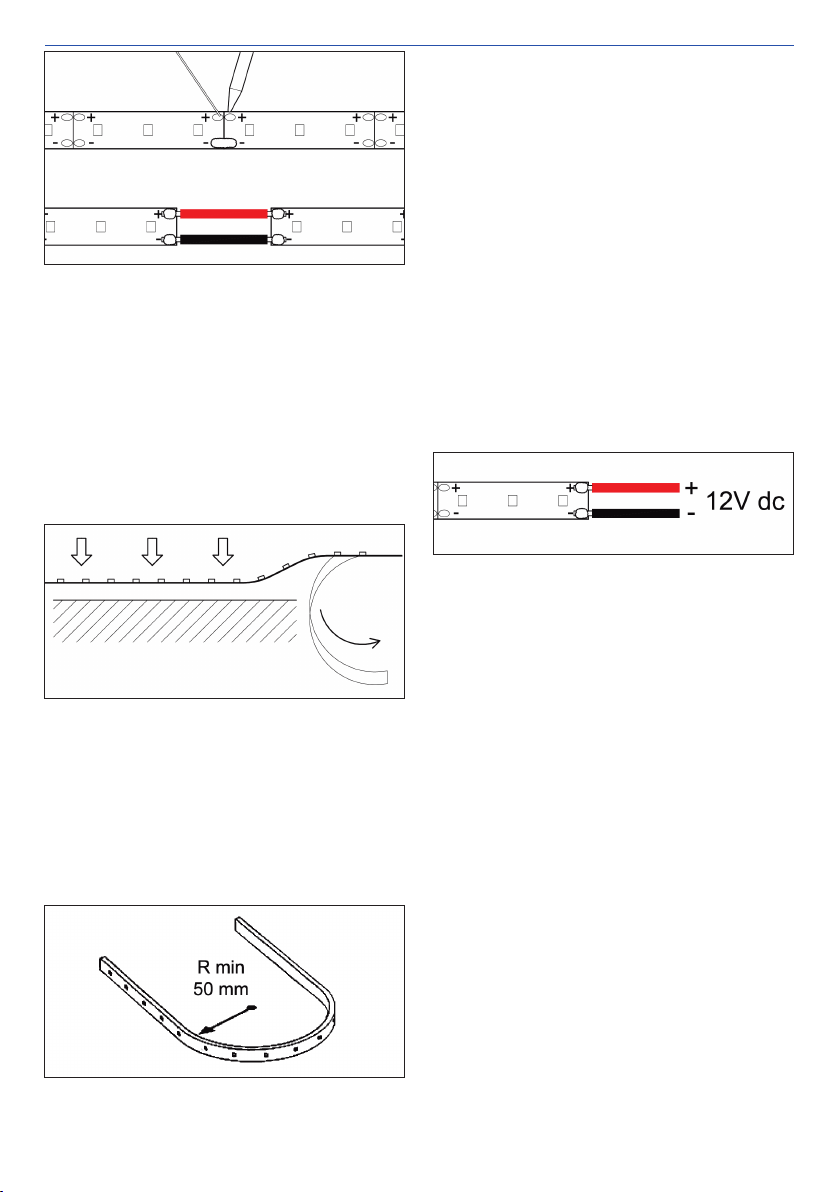
Whenthestripiscutorwhentwopiecesarewelded
togetherorwhenthesupplywiresareweldedtothe
strip,itisnecessarytocheckduringinstallationthat
there are no copper smears or welding points that
touch the metal surfaces: parasitic short circuits
betweenthecopperpadsandthemetalsurfacecan
turnoffsomesegments of LEDs,causinga device
malfunction,or theycan havedamaging effects on
thepowersupplies.
Tomeetdifferentinstallationrequirements,theLED
strip can be sectioned with standard scissors at
regularintervalssoastobeabletorealizesegments
ofvariablelengths.Theexactsectioningpointisthat
correspondingtothecopperpadsthatreplicatethe
+/LEDsupplylabels:cutaccuratelyalongtheblack
dividinglinedrawnbetweenthetwopairsoffacing
pads. For construction requirements, the minimum
croppingunitisa25mmlongsegment).
A cut in any other position of the strip irreparably
damages the segment enclosed between the pad
series,whichthereforecannolongerbeswitchedon.
For each new piece made it is necessary to apply
the supply wires, plugging the power adaptors
includedovertheedgeofthestrip.Payattentionto
the polarity +/ printed on the edge and the colors
red/blackoftheadaptors.
Otherwiseyoucanweldgenericpowersupplywires
usingasolderingiron.Duringweldingdonotexceed
the maximum time of 10 seconds of application of
the welder and keep the maximum welding
temperature lower than 260°C. The colors of the
wiresmustbeeasilyunderstood,soasnottomake
mistakes in the subsequent installation phases. If
possible use the same colors as the wires on the
head of the original reel and apply labels with the
polarityindicated.
In the same way, shorter lengths can be welded
togethertoobtain asegmentof thedesiredlength.
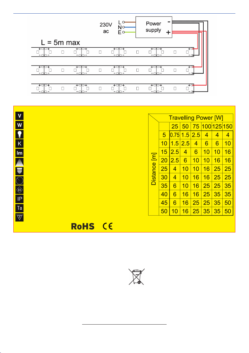
Neverexceedthemaximumtotallengthof5meters.
The welding can be carried out using the copper
padsdirectly,surmountingthetwosectionsontheir
end part, or by means of electric wires if it is

3/4
USER'SMANUAL
necessary to make curves or angles. Respect the
+/polarityofthepadsduringwelding.
When the layout of your installation is determined,
removetheprotectivetapefromtheadhesivealittle
bitatatimeandpresstheLEDstripfirmlytoadhere
the adhesive to the laying surface (refer to the 3M
tape application techniques). Continue in this way
until the piece is completed. Even during the
installation,absolutelyavoidbendsandtwistsofthe
strip because, as seen, you can damage the
conductivetracks and weldingsof smd LEDs, thus
compromising the good electrical contact between
LEDsandtracks.
TheLEDstripcanalsobefixedonacurvedsurface:
in this case the minimum radius of curvature must
begreaterthan5cm.Thestripmustalsobecurved
at the printed circuit areas which do not contain
electroniccomponentstopreventdetachmentofthe
componentsthemselves;thecurveshouldbemade
asingletimeandatthatpointthestripmustbefixed
in the position reached so as not to cause the
printed circuit to break due to stress by cyclic
flexions.
SupplytheLEDstripwiththevoltageindicatedonthe
nameplate label. Respect the correct electrical
polarity of the connections: a wrong polarity can
irreparablydamagetheelectroniccomponents.The
striprequiresacontinuoussupplyvoltageof12VDC.
The power supply must be chosen based on the
total power consumption of all the LED strips
connected in the same ignition unit; once you get
thisvalue, you canchoose fromthe widerange of
powersuppliesthatArenaLucimakesavailable.Itis
advisable to leave a margin of at least 25% lower
than the driving capacity of the chosen power
supply.
Connectthepowerlinesofthevariouspiecestothe
output terminals of the power supply or controller,
paying attention to the polarity of the respective
connecting wires. Connect the LED anode line
(marked+12Voragenericredwire)tothepositive
terminal of the power supply or to the positive
terminalofthecontrolleroutputs.ConnecttheLED
cathodeline(marked""oragenericblackwire)to
thenegativeterminalofthepowersupplyor tothe
negativeterminalofthecontrolleroutputs.
To guarantee a uniform brightness between the
beginningandtheendofthestrip,itisadvisablenot
to exceed a continuous length of 5 meters. This
meansthatinthepresenceofsegmentslongerthan
5m you have to cut the strip into several sections
with a maximum length of 5m and then connect
togetherthevariouspiecesinparallelontheoutputs
of the power supply or controller. Also, serial
connection is not recommended because the
greater current circulating along the series can
causedangerousoverloadsonthecoppertrackand
damagethestrip.Obviouslythelayingofthevarious
pieceswillthenbeconductedinordertorestorethe
visualeffectofasingleline(seeFig.01).
A furtherprecautiontobetakenintoaccountduring
theelectricalconnectionofthevariousstripsegments
is the conductor cross section. It is essential to
evaluate the voltage drop along the connecting
cablessoastoensureavoltageatthebeginningof
the strip not too lower than the nominal supply
voltage,otherwisetheLEDswillnotlightuporturnon
butatalowerintensitylevel(seethetable).
Connect the power supply to the mains socket to
turnontheLEDstrip,respectingthepolarityLNE
indicated on the power supply (colors brown = L,
blue=N,yellow/green=E).Followtheinstructions
givenintheusermanualoftheeventualcontrollerto
beabletomanagethevariousfunctionsavailable.

4/4
LS1532
Fig.01Generalwiringdiagram
ArenaLucisrlviaSvizzera12/1446042CastelGoffredo(MN),Italy
Tel.+390376782411Fax+390376780973
www.arenaluci.com[email protected]
WARRANTYCONDITIONS
Theunitisguaranteedfor24monthsfromthedateofpurchase
againstdefectsinworkmanshipormaterialsthatcomposeit.
Thiswarrantydoesfaultsduetoincorrectorimproperuseof
thedevice.
Thewarrantyisimmediatelyvoidiftheunithasbeentampered
withoropenedbyunauthorizedpersonnel.
Thewarrantyprovides,atthediscretionofArenaLuci,repairor
replacementoffaultyequipment.
The serial number and model of the device are required to
obtaininformationorassistancefromthedealer.Weinviteyou
totranscribethem intime: foranyrequestof information or
services,thiswillresultinaquickandeffectiveoperation.
CERULES
ThedevicemeetstheessentialrequirementsoftheDirectives
LVD 2014/35/UE, EMC 2014/30/UE, RAEE 2012/19/UE,
RoHS 2011/65/UE, Ecodesign 2009/125/CE reg. (UE)
1194/2012,Energylabel2010/30/UEreg.(UE)874/2012
reg.(UE)518/2014,GPSD2001/95/CE.
Warnings
DisposalofOldElectrical&ElectronicEquipment(applicable
intheEuropeanUnionandotherEuropeancountrieswithse
paratecollectionsystems).
Theproductshallnotbetreatedashouseholdwaste
butmustbehandedovertotheapplicablecollection
point for the recycling of electrical and electronic
equipment. By ensuring this product is correctly
disposed, you will help prevent potential negative conse
quencesfortheenvironmentandhumanhealth,whichcould
otherwisebecausedbyinappropriatewastehandling.There
cyclingofmaterialswillhelptoconservenaturalresources.For
moredetailedinformationaboutrecyclingofthisproduct,plea
se contact your city office, your household waste disposal
serviceoryoursupplier.
Powersupply
Powerconsumption
Lightsource
ColourTemp.
Luminousflux
Beamangle
Socket
Curvature
Insulationclass
Protectionrating
Operatingtemp.
Suitabletobemountedonnormallyinflammablesurfaces
Applicablestandards
12VDC
15W/m75W/5m
120smdLED/m600smdLED/5m
3200K(WW)6000K(W)
840lm/m(WW)1080lm/m(W)
120°
Cable
Minimumradius50mm
III
IP20
25°C...+40°C
TECHNICALSPECIFICATION
LS1532ENR0|09/2018
Table01Cablecrosssectioninmm2
This manual suits for next models
1
Popular Lighting Equipment manuals by other brands

Astral Pool
Astral Pool Control Cloro Libre installation instructions

LIVARNO LUX
LIVARNO LUX 970-M manual

Compu Pool Products
Compu Pool Products GRC/J1400-3 instruction manual

Show Tec
Show Tec Compact Power Lightset V@ manual

Lightmybricks
Lightmybricks LEGO JAZZ CLUB 10312 installation guide

North Light
North Light WX-5VLED44-C-80MC-10-1 instruction manual