4
1.1 Introduction
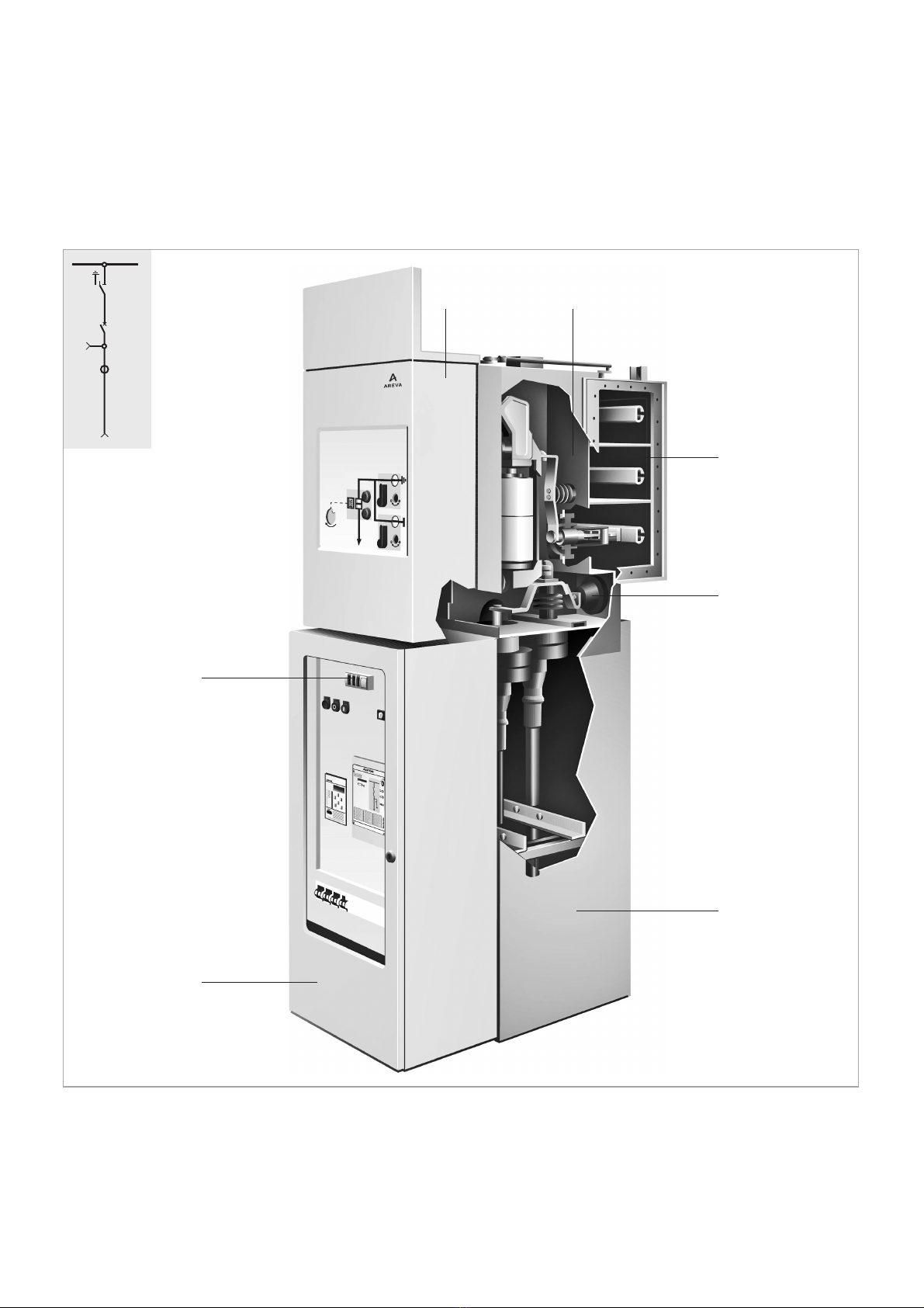
These Technical Instructions de-
scribe the operation of gas-insulated
WS medium-voltage switchgear.
These instructions are an integral
part of the product. It must be made
available at any time to the persons
who work on the switchgear. If the
switchgear is ever relocated, it must
be accompanied by this documenta-
tion.
The following additional documents
for this switchgear must be ob-
served:
•Purchase contract with the agree-
ments on the configuration of the
switchgear and with the legal
details
•Installation Instructions
•the contract specific switchgear
circuit diagrams / documentation
•the Operating Instructions of the
devices installed in the switchgear
(e.g. IVIS, devices in low-voltage
cabinet)
•the Instructions for Assembly pro-
vided by the manufacturer of the
cable connection systems to be
connected to the switchgear
•the System Configuration “WS”
•the Technical Instructions “Use
and handling of insulating gas”
for WS (can be requested as
required).
As our products are subject to conti-
nuous further development, we
reserve the right to make changes
regarding standards, illustrations and
technical data.
1.2 Terms and symbols
used
This manual uses certain symbols
which warn about dangers or pro-
vide important information which
must be observed to avoid danger to
personnel and damage to equip-
ment:
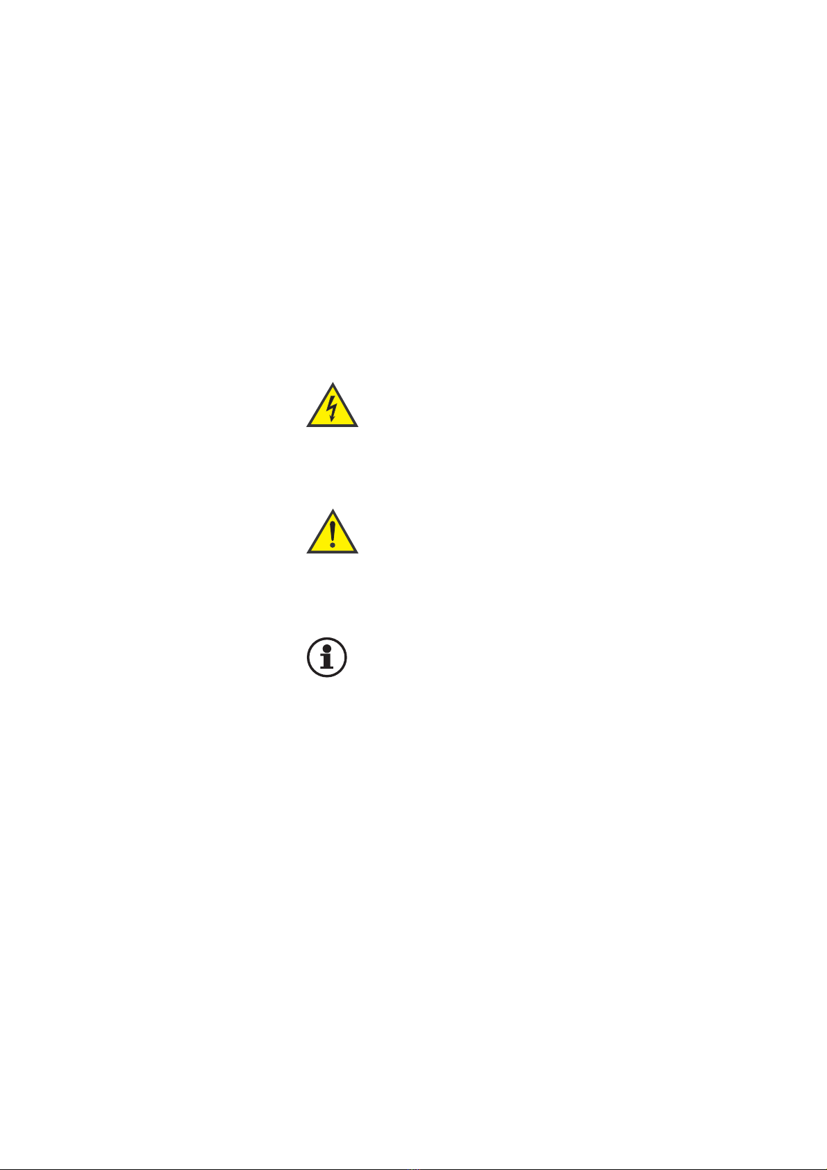
Warning!
This symbol warns of
dangerous electrical
voltage. Contact with
live parts may result in fatal
injury!
Warning!
This symbol indicates
important instructions.
Non-compliance may
result in serious injury, death
or damage to the equipment.
Important!
This symbol is used for
information which is impor-
tant to avoid damage.
1.3 Use in accordance
with the intended
purpose
WS gas-insulated medium-voltage
switchgear units are exclusively
intended for switching and distribu-
ting electrical power. They may only
be used in the scope of the speci-
fied standards and the appropriate
switchgear-specific technical data.
Any other use constitutes improper
use and may result in dangers and
damage.
Disclaimer of liability
The manufacturer shall not be held
responsible for damage which
occurs if:
•instructions in this manual are not
complied with,
•the switchgear is not operated
according to its intended use
(see above),
•the switchgear is assembled,
connected or operated improperly,
•accessories or spare parts are
used which have not been appro-
ved by the manufacturer,
•the switchgear is modified without
the manufacturer’s approval, or if
inadmissible parts are attached.
No liability is accepted for parts pro-
vided by customers, e.g. current
transformers.
1 Regulations and provisions
>>