User and Programming Manual
6 XDS Series
Table of Contents
1
Introduction.................................................................................................................................. 10
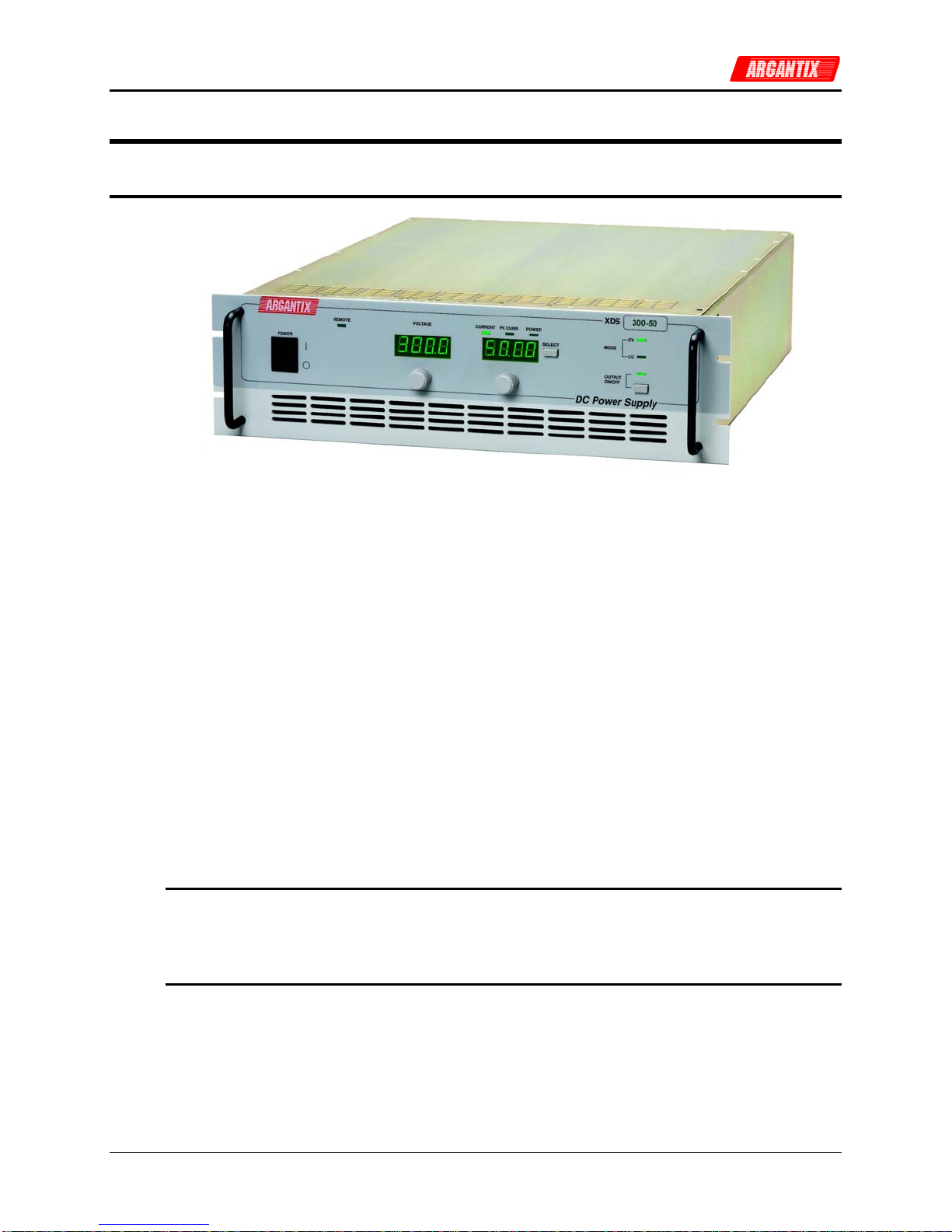
1.1
General Description............................................................................................................................. 10
1.2
Bench Top use.................................................................................................................................... 11
1.3
Equipment Rack use........................................................................................................................... 11
2
Specifications............................................................................................................................... 12
2.1
Electrical.............................................................................................................................................. 12
2.2
Measurements .................................................................................................................................... 15
2.3
Environmental ..................................................................................................................................... 17
2.4
Mechanical.......................................................................................................................................... 17
2.5
Agency Approvals ............................................................................................................................... 18
2.6
Remote Control Interfaces .................................................................................................................. 18
2.7
Protection............................................................................................................................................ 19
2.8
Controls and Indicators ....................................................................................................................... 19
2.9
Parallel Operation................................................................................................................................ 19
2.10
Factory Configuration Options......................................................................................................... 20
2.11
-LC Option....................................................................................................................................... 20
3
Installation and Functional Test................................................................................................... 21
3.1
Inspection............................................................................................................................................ 21
3.2
Location and Mounting........................................................................................................................ 21
3.3
Input / Output Connectors................................................................................................................... 22
3.4
Wire Sizing and Lug Size.................................................................................................................... 25
3.5
AC Input Wiring................................................................................................................................... 26
4
Front Panel Operation ................................................................................................................. 28
4.1
Functional Controls ............................................................................................................................. 28
4.2
How to examples................................................................................................................................. 31
4.3
Setting the Power on Initialization Values............................................................................................ 33
4.4
Operating Modes................................................................................................................................. 34
4.5
Special Features ................................................................................................................................. 35
5
Model Configurations................................................................................................................... 37
5.1
Available Configurations...................................................................................................................... 37
5.2
Changing Configurations..................................................................................................................... 38
5.3
Stand Alone Configuration .................................................................................................................. 40
5.4
Parallel Mode ...................................................................................................................................... 40
5.5
RPV Mode........................................................................................................................................... 43
5.6
RPC Mode........................................................................................................................................... 43
6
Principle of Operation.................................................................................................................. 44
6.1
General ............................................................................................................................................... 44
6.2
Overall Description.............................................................................................................................. 44
6.3
Bias Power Supply (A7)....................................................................................................................... 47
6.4
Power Module (A9 through A11)......................................................................................................... 48
6.5
Controller Module (A3)........................................................................................................................ 50
7
Calibration.................................................................................................................................... 52
7.1
Calibration Equipment......................................................................................................................... 52
7.2
Routine Calibration.............................................................................................................................. 53
7.3
Non-Routine Calibration...................................................................................................................... 56