Page 1 www.argo-hytos.com
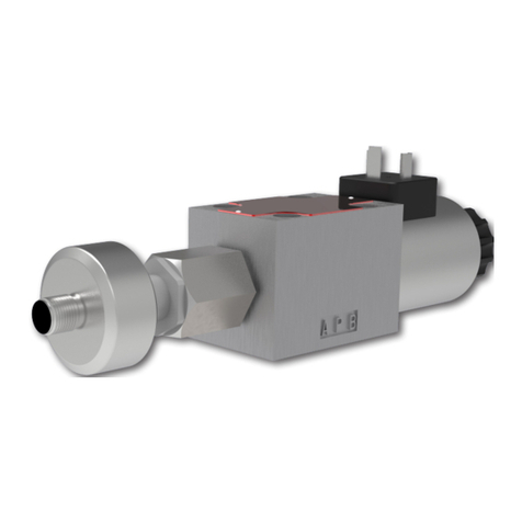
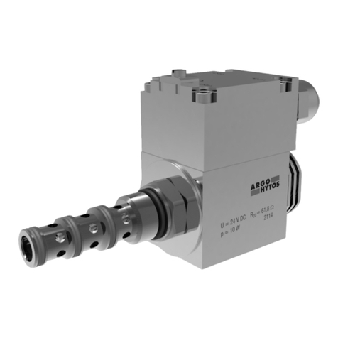
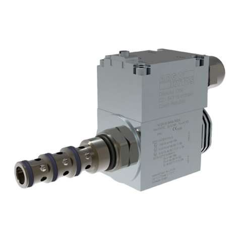
Proportional Directional Control Valve PRM7
Obsah
1. General technical parameters ............................................................................................................................... 2
1.1. Introduction ......................................................................................................................................................... 2
1.2. Valves Usage ........................................................................................................................................................ 2
1.3. Limited Warranty................................................................................................................................................... 2
1.4. Used Symbols ....................................................................................................................................................... 2
1.5. Caution ............................................................................................................................................................... 2
1.6. Service, Maintenance, Repairs ................................................................................................................................. 3
1.7. Basic Setting......................................................................................................................................................... 3
2. Technical Description ............................................................................................................................................. 3
2.1. Basic Parts............................................................................................................................................................ 3
2.2. Technical Parameters.............................................................................................................................................. 3
3. Design of Valves .................................................................................................................................................... 4
3.1. Configuration E01 (directly operated proportional directional control valve).................................................................... 4
3.2. Configuration E02S01 – (proportional directional control valve with internal spool position feedback)................................ 4
3.3. Configuration E03 – (proportional directional control valve with external feedback)......................................................... 4
3.4. Configuration E04S01 – (proportional directional control valve with internal spool position feedback and external feedback . 4
4. Valve Assembly ..................................................................................................................................................... 5
5. Electrical Connection ............................................................................................................................................ 5
5.1. Connection of Power Supply and Command Signal to the Valve Electronics ................................................................... 5
5.2. Connection of a Cable for Electronics Parameters Setting............................................................................................ 5
5.3. Connection of the External Feedback Cable .............................................................................................................. 6
5.4. Putting into Operation ........................................................................................................................................... 6
6. Digital Integrated Electronics .............................................................................................................................. 6
6.1. Electronics Block Diagram....................................................................................................................................... 6
6.2. Setting of the Electronics Parameters ....................................................................................................................... 7
7. Configuration Program PRM7Conf....................................................................................................................... 7
7.1. Basic Description ................................................................................................................................................... 7
7.2. Installation ........................................................................................................................................................... 7
7.3. User Interface ....................................................................................................................................................... 7
7.3.1. Main Menu .................................................................................................................................................... 8
7.3.2. Toolbar .......................................................................................................................................................... 8
7.3.3. Status Line ..................................................................................................................................................... 9
7.3.4. Desktop ......................................................................................................................................................... 9
7.4. Communication with the Valve Electronics .............................................................................................................. 10
7.4.1. Communication Setting ................................................................................................................................. 10
7.4.2. Communication Establishment ........................................................................................................................ 10
7.4.3. Uploading Data from the Valve Electronics ........................................................................................................ 11
7.4.4. Downloading Data to the Valve Electronics........................................................................................................ 11
7.4.5. Status of the Valve Electronics ......................................................................................................................... 11
7.4.6. Reset of the Valve Electronics .......................................................................................................................... 11
7.5. Possibilities of Setting the Valve Electronics Parameters ............................................................................................. 11
7.5.1. Parameters table ........................................................................................................................................... 11
7.5.2. Block Diagram .............................................................................................................................................. 12
7.5.3. Setting According to the Ordering Code ........................................................................................................... 12
7.5.4. Setting from a Prepared Configuration File ....................................................................................................... 13
7.6. Block Diagrams and Tables of Parameters of Basic Configurations .............................................................................. 13
7.6.1. Configuration E01 ......................................................................................................................................... 13
7.6.2. Configuration E02S01.................................................................................................................................... 14
7.6.3. Configuration E03 ......................................................................................................................................... 16
7.6.4. Configuration E04S01.................................................................................................................................... 17
7.7. Basic Configuration Blocks Detailed Description ....................................................................................................... 19
7.7.1. Directional Valve Configuration ....................................................................................................................... 19
7.7.2. Command Signal Type Selection ...................................................................................................................... 19
7.7.3. Command Signal Polarity ............................................................................................................................... 19
7.7.4. Threshold .................................................................................................................................................... 20
7.7.5. Ramp Functions ............................................................................................................................................ 20
7.7.6. Command Signal Gain ................................................................................................................................... 20
7.7.7. Dead Band Compensation ............................................................................................................................. 21
7.7.8. Current Limiting............................................................................................................................................ 21
7.7.9. Dither .......................................................................................................................................................... 21
7.7.10. Internal and External Feedback Controllers ...................................................................................................... 22
7.7.11. Type of External Feedback Signal.................................................................................................................... 22
7.7.12. External Feedback Signal Polarity.................................................................................................................... 22
7.7.13. External Feedback Signal Offset ..................................................................................................................... 23
7.7.14. External Feedback Signal Gain ....................................................................................................................... 23
7.7.15. Linearization Function ................................................................................................................................. 24
7.8. Measurement ..................................................................................................................................................... 24
Content
User Manual
