Argo-Hytos OPCom User manual

Subject to change · V 2.02.20 · EN
Page 1
www.argo-hytos.com
Safety and operating instructions
Read safety and operating instructions before use.
Note: The indicated data only serve to describe the product.
Information regarding the use of this product are only examples and suggestions.
Catalog specifications are no guaranteed features.
The information given does not release the user from his / her own assessments and inspections.
Our products are subject to a process of natural wear and aging.
© All rights are reserved by ARGO-HYTOS GMBH, even in the event of industrial property rights.
Any right of disposal such as copying and distribution rights shall remain with us.
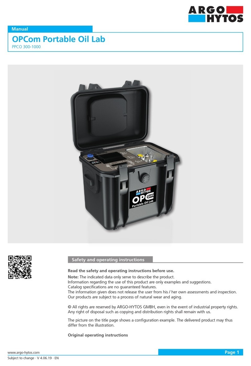
The picture on the title page shows a configuration example. The delivered product may thus differ
from the illustration.
Original instruction
OPCom Particle Monitor
SPCO 300-1000 / 2000 / 1200
Operating Manual

Subject to change · V 2.02.20 · EN
Page 2 www.argo-hytos.com
Contents
OPCom
Contents .....................................................................................................................................................................2
1. About this documentation.......................................................................................................................................5
1.1 Applicability of this documentation..............................................................................................................................5
1.2 Required and supplementary documentation ...............................................................................................................5
1.3 Presentation of information .........................................................................................................................................5
1.3.1 Safety instructions ......................................................................................................................................................5
1.3.2 Symbols.......................................................................................................................................................................6
1.3.3 Terms...........................................................................................................................................................................6
1.3.4 Abbreviations ..............................................................................................................................................................6
2. Safety instructions....................................................................................................................................................7
2.1 About this chapter.......................................................................................................................................................7
2.2 Intended use................................................................................................................................................................7
2.3 Improper use ..............................................................................................................................................................7
2.4 Reasonably foreseeable misuse ....................................................................................................................................7
2.5 Qualification of personnel ...........................................................................................................................................7
2.6 General safety instructions...........................................................................................................................................8
2.7 Product and technology related safety instructions ......................................................................................................8
2.8 Indications on the product ..........................................................................................................................................8
3. General instructions ...............................................................................................................................................10
4. Scope of delivery ....................................................................................................................................................11
5. About this product..................................................................................................................................................12
5.1 Functional description................................................................................................................................................12
5.2 Component overview ................................................................................................................................................13
5.3 Identification of the product ......................................................................................................................................13
6. Transport and storage ............................................................................................................................................14
7. Assembly .................................................................................................................................................................15
7.1 Operating site............................................................................................................................................................15
7.2 Hydraulic connection .................................................................................................................................................15
7.3 Mounting ..................................................................................................................................................................16
7.4 Mechanical stress.......................................................................................................................................................17
8. Electrical connection...............................................................................................................................................18
8.1 Pin assignment (view from above)..............................................................................................................................18
9. Commissioning........................................................................................................................................................19
9.1 Before commissioning ...............................................................................................................................................19
10. Start screen .............................................................................................................................................................20
10.1 Status display.............................................................................................................................................................20
10.2 Time display...............................................................................................................................................................20
10.3 Displayed standard ....................................................................................................................................................20
10.4 Ordinal numbers........................................................................................................................................................20
11. Menu and operation...............................................................................................................................................21
11.1 Menu structure..........................................................................................................................................................22
11.2 Operating modes.......................................................................................................................................................23

Subject to change · V 2.02.20 · EN
Page 3
www.argo-hytos.com
11.2.1 Time-controlled measurement ...................................................................................................................................23
11.2.2 Digital I/O ..................................................................................................................................................................23
11.2.3 Button .......................................................................................................................................................................23
11.2.4 Automatic .................................................................................................................................................................24
11.3 Alarm configuration...................................................................................................................................................24
11.3.1 Alarm type.................................................................................................................................................................24
11.3.1.1 Standard alarm ..........................................................................................................................................................24
11.3.1.2 Filter mode ................................................................................................................................................................25
11.3.1.3 Temperature alarm.....................................................................................................................................................25
11.3.2 Alarm memory...........................................................................................................................................................25
11.3.3 Low-pass filter ...........................................................................................................................................................25
11.4 Configuration analog.................................................................................................................................................26
11.5 Standard....................................................................................................................................................................27
11.6 Configuration flow ....................................................................................................................................................27
11.6.1 Automatic .................................................................................................................................................................27
11.6.2 Fix .............................................................................................................................................................................27
11.7 Communication.........................................................................................................................................................27
11.7.1 Type...........................................................................................................................................................................27
11.8 Baud rate CAN ..........................................................................................................................................................28
11.8.1 Node ID CAN.............................................................................................................................................................28
11.8.2 Baud rate RS232........................................................................................................................................................28
11.8.3 Automatic transmission .............................................................................................................................................28
11.9 Configuration display.................................................................................................................................................29
11.10 Sensor parameter ......................................................................................................................................................29
11.10.1 Measurement results..................................................................................................................................................29
11.10.2 Electronics .................................................................................................................................................................29
11.10.3 Operating hours ........................................................................................................................................................30
11.10.4 Error info ...................................................................................................................................................................30
11.10.5 Flow settings .............................................................................................................................................................30
11.11 Language ..................................................................................................................................................................30
12. Calibration...............................................................................................................................................................31
12.1 Calibration note.........................................................................................................................................................31
13. Analog current output (4...20mA) .........................................................................................................................32
13.1 Measurement without load resistance .......................................................................................................................32
13.2 Measurement with load resistance.............................................................................................................................32
13.3 Configuration ............................................................................................................................................................32
13.4 Conversion of the analog current output to the ordinal number.................................................................................32
13.5 Sequential data output for ISO 4406:17 and SAE AS 4059E.......................................................................................33
14. Switching inputs and outputs ...............................................................................................................................34
14.1 Digital input...............................................................................................................................................................34
14.2 Switching output .......................................................................................................................................................34
14.2.1 Option 1....................................................................................................................................................................34
14.2.2 Option 2....................................................................................................................................................................35
15. Communication RS232............................................................................................................................................36
15.1 Interface parameters..................................................................................................................................................36
15.2 Read commands .......................................................................................................................................................36
15.3 Configuration commands ..........................................................................................................................................38
15.4 Checksum calculation (CRC) ......................................................................................................................................41
16. Communication CAN ..............................................................................................................................................42
16. 1 CANopen ..................................................................................................................................................................42
16.1.1 „CANopen Object Dictionary“ in general...................................................................................................................43
16.1.2 CANopen Communication Objects ............................................................................................................................43
16.1.3 Service Data Object (SDO)..........................................................................................................................................44
16.1.4 Process Data Object (PDO) .........................................................................................................................................46
16.1.5 PDO Mapping............................................................................................................................................................46
16.1.6 „CANopen Object Dictionary“ in detail......................................................................................................................48
16.2 CAN J1939 ................................................................................................................................................................53

Subject to change · V 2.02.20 · EN
Page 4 www.argo-hytos.com
17. Classification systems.............................................................................................................................................54
17.1 Definition of particle sizes ..........................................................................................................................................54
17.1.1 Cleanliness classes according to ISO 4406:17.............................................................................................................54
17.1.2 Cleanliness classes according to SAE AS 4059E ..........................................................................................................55
17.1.3 Cleanliness classes according to NAS 1638.................................................................................................................56
17.1.4 Cleanliness classes according to GOST 17216 ............................................................................................................57
18. Maintenance and repair .........................................................................................................................................58
18.1 Maintenance .............................................................................................................................................................58
18.2 Repair........................................................................................................................................................................58
19. Decommissioning, disassembly, disposal .............................................................................................................59
19.1 Environment ..............................................................................................................................................................59
20 Accessories ..............................................................................................................................................................60
21. Troubleshooting......................................................................................................................................................61
22. FAQ ..........................................................................................................................................................................62
23. Technical data..........................................................................................................................................................64
23.1 Technical data............................................................................................................................................................64
23.2 Dimensional drawing .................................................................................................................................................65
24. Appendix .................................................................................................................................................................66
24.1 Cable lengths ............................................................................................................................................................66
24.2 Coding of error bits ...................................................................................................................................................66
24.3 Particle contaminations..............................................................................................................................................68

Subject to change · V 2.02.20 · EN
Page 5
www.argo-hytos.com
1. About this documentation
1.1 Applicability of this documentation
This documentation is applicable for the following products:
›OPCom Particle Monitor
›OPCom Particle Monitor Phosphate Ester
›OPCom Particle Monitor without display
This documentation is written for service engineers, technicians, operators and system operators.
This document contains important information for safe and appropriate assembly, transport, activation, operation, usage, servicing,
dismantling and simple troubleshooting.
›Read this document completely and in particular the chapter, “Safety Instructions,” before you work with the product.
1.2 Required and supplementary documentation
Title Number of document Document type
Data sheet 100.50 Data sheet
Quick start 29808300 Quick start
1.3 Presentation of information
So that this document can help you to work quickly and safely with your product, we use standardized safety instructions, symbols,
terms and abbreviations. For better understanding, these are explained in the following sections.
1.3.1 Safety instructions
In this documentation, safety instructions are faced with a sequence of actions which would result in the danger of personal injury or
damage to equipment. The measures described to avoid theses hazards must be observed.
Safety instructions are structured as follows:
SIGNAL WORD
Type and source of danger
Consequences of non-compliance
›Measures for safety and hazard defense
›<List>
›Warning signal: draws attention to the danger
›Signal word: indicates the severity of the danger
›Type and source of danger: specifies the type and source of danger
›Consequences: describes the consequences of non-compliance
›Measures: describes how to deal with the risk
Warning sign, signal word Meaning
DANGER Indicates a dangerous situation which results in death or serious injury if not avoided.
WARNING Indicates a dangerous situation which may result in death or serious injury if not avoided.
CAUTION Indicates a dangerous situation which may result in light to moderate injury if not
avoided.
NOTE Indicates equipment damage: The product or surrounding could be damaged.
Table 1: Required and supplementary documentation
Table 2: Meaning of warning signs

Subject to change · V 2.02.20 · EN
Page 6 www.argo-hytos.com
1.3.2 Symbols
The following symbols indicate notes which are not safety-relevant but increase the intelligibility of the documentation.
Symbol Meaning
If this information is not observed, the product can not optimally be used or operated
This symbol warns against laser beams.
Singular, independent action step / instruction
1.
2.
Numbered instruction
The numbers indicate that the action steps follow one another
1.3.3 Terms
In this documentation the following terms are used:
Term Meaning
µm(c) Size specification for particles when using ISO-MTD
1.3.4 Abbreviations
Abbreviation Meaning
OL Ordinal number
APC Automatic particle counter
MTD Medium test dust
mm Double-digit indication of minutes
ss Double-digit indication of seconds
Table 3: Meaning of symbols
Table 4: Terms
Table 5: Abbreviations

Subject to change · V 2.02.20 · EN
Page 7
www.argo-hytos.com
2. Safety instructions
2.1 About this chapter
This product was manufactured according to the generally recognized standards of engineering. Nevertheless, there is a danger of
injury or damage if you do not observe this chapter and the safety instructions in this documentation.
Read this document thoroughly and completely before working with the product.
Retain this document and ensure that it is available for all users at all times.
Always include the necessary documentation when passing the equipment along to a third party.
2.2 Intended use
This product is a hydraulic component.
The device is an optical particle monitor, to monitor the cleanliness of fluids.
It works according to the principle of light extinction (reduction of radiation) and measures particles in the fluid.
The measured values are converted to standardized cleanliness classes and shown on the display. Via different interfaces, the
measurement data can be read out and transferred.
The connection to the fluid system is effected via two Minimess©-connections M16x2.
You may use the product for the following:
›Monitoring of cleanliness of a fluid
›Trend analysis of the contamination degree
The product is intended for professional use only, not for private use.
"Intended use" also includes that you have completely read and understood this documentation, in particular Chapter 2
"Safety Instructions".
2.3 Improper use
Any other use than the intended use described, is improper and inadmissible.
If unsuitable products are installed or used in safety-related applications, unintended operating states can occur in the application,
which can cause personal injury and / or material damage. Therefore only use this product in safety-related applications if this use is
expressly specified and permitted in the product‘s documentation, e.g. in explosion protection areas or in safety-related parts of a
control system (functional safety).
ARGO-HYTOS GmbH assumes no liability for damages resulting from improper use. The risks associated with improper use are solely
with the user.
2.4 Reasonably foreseeable misuse
The delivery of the following media is forbidden:
›Others than listed in Chapter 24.1 "Technical Data".
The operator alone is liable for damages resulting from improper use.
2.5 Qualification of personnel
The operations described in this document require fundamental knowledge of mechanics and hydraulics as well as knowledge of the
appropriate technical terms. In order to ensure safe use, these operations may therefore only be carried out by a correspondingly
skilled worker or an instructed person under the guidance of a skilled worker.
A skilled worker is someone who can - based on his / her technical education, knowledge and experience as well as knowledge of
the respective regulations of the jobs assigned to him / her - recognize possible dangers and ensure appropriate safety measures. A
skilled worker must observe the relevant technical regulations.

Subject to change · V 2.02.20 · EN
Page 8 www.argo-hytos.com
2.6 General safety instructions
›Observe the valid regulations for accident prevention and environmental protection.
›Observe the safety regulations and requirements of the country in which the product is used / applied.
›Only use ARGO-HYTOS products that are in technically perfect condition.
›Observe all instructions on the product.
›People who assemble, operate, disassemble or maintain ARGO-HYTOS products may not do so under the influence of alcohol,
other drugs or medications that affect the responsiveness.
›Only use manufacturer-approved accessories and spare parts, in order to prevent personal danger due to unsuitable
spare parts.
›Observe the technical data and ambient specifications specified in the product documentation.
›If unsuitable products are used or installed in safety-relevant applications, unintended operating states can occur in the application,
which can cause personal injury and / or material damage. Therefore only use the product in safety-relevant applications if this use
is expressly specified and permitted in the product‘s documentation.
›You may only put the product into operation, when it has been established that the final product (e.g. a machine or system), into
which the ARGO-HYTOS products are installed, complies with the country-specific regulations, safety regulations and standards of
the application.
2.7 Product and technology related safety instructions
CAUTION
Laser
The OPCom Particle Monitor contains a laser sensor that is classified for intended use as a class 1 laser according to DIN
EN 60825-1:2001-11. In reasonably foreseeable circumstances, the accessible laser radiation is not dangerous.
With direct exposure to class 1 lasers in the upper power range, injury, such as blinding, impairment of color vision and
disruption, cannot be ruled out.
2.8 Indications on the product
On the back of the device there is the nameplate (Fig. 1/1) and the note with the laser class (Fig. 1/2).
1
2
3
Fig. 1: Indication laser class

Subject to change · V 2.02.20 · EN
Page 9
www.argo-hytos.com
NOTE
Functional limitation
Damage of the pressure compensation membrane.
Impairment of protection class IP67.
On the back of the device there is a pressure compensation membrane (Fig. 1/3), which must not be damaged. Be careful while
working on the backside.
On the side of the device, between a Minimess connection and the connector for the sensor cable, a label indicates the laser
radiation.
Fig. 2: Label laser radiation

Subject to change · V 2.02.20 · EN
Page 10 www.argo-hytos.com
For prevention of material damage and product damage
CAUTION
Danger due to improper handling!
Material damage!
The OPCom Particle Monitor may only be used in accordance with Section 2-2, “Intended use”.
Leakage or spillage of hydraulic fluid!
Environmental pollution and ground water pollution!
Use oil binding agents in order to bind leaked hydraulic oil.
Contamination due to fluids and foreign bodies!
Premature wear - malfunction - risk of damage - material damage
Pay attention to cleanliness when assembling in order to prevent foreign bodies, such as welding beads or metal chips, from
entering the hydraulic lines and leading to premature wear or malfunction.
Make sure that connections, hydraulic lines and attachment parts (e.g. gauges) are free of dirt and chips.
Check prior to commissioning that all hydraulic and mechanical connections are connected and tight, and that all gaskets and
seals of the plug connectors are correctly assembled and undamaged.
For removal of lubricants and other contaminants, use residue-free industrial wipes.
Make sure that connections, hydraulic lines and attachment parts are clean.
Ensure that no contaminants enter when closing the connections.
Make sure that no detergents enter the hydraulic system.
Do not use cotton waste or faying cleaning rags for cleaning.
Do not use hemp as sealing agent.
3. General instructions

Subject to change · V 2.02.20 · EN
Page 11
www.argo-hytos.com
4. Scope of delivery
The package includes:
›1 OPCom Particle Monitor
›1 Quick Start Guide

Subject to change · V 2.02.20 · EN
Page 12 www.argo-hytos.com
5. About this product
5.1 Functional description
The OPCom Particle Monitor is an optical particle monitor operating on the principle of light extinction.
A
C
B
Fig. 3: Design and measuring principle of a particle monitor
It consists of a flowed measuring cell (A), a laser (B) and a photo diode (C).
The laser beams through the measuring cell to the opposite photo diode. If a particle passes through the laser beam, the light
intensity detected by the photo diode is reduced. The larger the particle, the greater the reduction in intensity.
The OPCom Particle Monitor allows users to monitor the contamination level and the trend regarding cleanliness of fluids. Differen-
ces in absolute precision may arise compared to particle counters calibrated according to ISO 11171:99. However, the deviation is
less than one scale number. Changes are shown with great precision.
Continuous monitoring of the cleanliness allows changes in the machine to be detected very quickly. Prompt warning allows
measures to be taken before the contamination increases to the point of damaging the entire system.

Subject to change · V 2.02.20 · EN
Page 13
www.argo-hytos.com
1 + 6 Hydraulic connection uid
The device is equipped with two Minimess©-Connectors M16x2. Usually two Minimess© hoses are added to connect the particle
monitor to the fluid system. The measurement is independent of the flow direction.
2 + 5 Front panel and display
The latest measured cleanliness classes and the time to the next measurement or the remaining measurement time is displayed.
3 Indicator light „Power“
If an operating voltage is applied, this indicator light glows green.
4 Indicator light „Alarm“
If there is an internal alarm, this indicator light glows red. Several alarms can be set in the device. Please read the manual for further
information.
7 Selection button []
The selection button leads to the next menu level or to the next position if values are to be set.
8 Button DOWN []
10 Button UP []
These buttons navigate through the menu and browse through entries.
9 Connection M12x1 sensor cable
The device is equipped with an 8 pole M12x1 connector for connection of a sensor cable. The pin assignment of the sensor cable
and its connection are included in this manual.
Further functions of the buttons:
›Back:
Simultaneous pressing of the buttons UP [] and DOWN [].
›Changing of values:
With the button UP [] or the button DOWN [] the required parameter can be marked in the menu structure. To choose this
parameter press the selection button, then the value can be changed with the UP [] or DOWN [] button. Changes are confir-
med by pressing the selection button after the last position of input ability. In case of a jump to the higher level before pressing
the selection button, the changes will not be saved.
5.3 Identification of the product
Fig. 5: Nameplate
123456
7
8
9
10
1 Hydraulic connection uid
2 Front panel and display
3 Indicator light „Power“
4 Indicator light „Alarm“
5 Display
6 Hydraulic connection uid
7 Selection button []
8 Button DOWN []
9 Connection M12x1 sensor cable 1
10 Button UP []
Fig. 4: Component overview
5.2 Component overview

Subject to change · V 2.02.20 · EN
Page 14 www.argo-hytos.com
6. Transport and storage
There are no special transport instructions for this product.
However, observe the instructions in Chapter 2, “Safety instructions”.
For storage and transport, observe the specified environmental conditions stated in the technical data.

Subject to change · V 2.02.20 · EN
Page 15
www.argo-hytos.com
7. Assembly
7.1 Operating site
Please follow these instructions when determining the mounting location:
›Connect the particle monitor in bypass flow to a pressure line.
›The flow direction is arbitrary.
›At the connection point there should preferably be constant pressure conditions.
The pressure may vary, but there must not be pressure peaks or strong fluctuations.
›The volume flow must be constant and be between 50 and 400 ml/min.
›A flow control or pressure reduction must always be installed downstream of the particle monitor, since these can generate
turbulences or air bubbles which cause measurement errors.
›If a pump is needed to generate the required flow, this should be a low pulsation pump which should be installed in the pressure
line since negative pressure on the suction side can lead to air bubbles which would cause measurement errors.
›If air bubbles occur in the system, a calming section in form of a hose of approx. 2 meters should be installed ahead of the sensor.
7.2 Hydraulic connection
The sensor has two ¼“-screw connections and is delivered from the factory with screwed Minimess connections. The system
pressure generates the required flow rate and needs to be throttled after the device. The flow direction can be chosen freely.
To be able to read the display and use the keyboard, the device should be installed at an accessible position. With the length of the
hoses, the risk of settling of larger particles increases. Furthermore, especially at higher viscosities and when using Minimess hoses, it
must be ensured that the pressure is sufficiently high to generate a flow between 50 and 400 ml/min.
The Minimess connections can be exchanged by other connectors.
A maximum tightening torque of 25 Nm shall not be exceeded.
While exchanging the connection couplings, no dirt, chips or other contaminations shall enter the interior of the device.
Fig. 6: Hydraulic connection, avoid blind holes in the supply line
The device should be installed at a relevant measurement location in the hydraulic circuit where constant pressure conditions exist.
The pressure may vary, but it must not show any peaks or strong fluctuations during the measurement.

Subject to change · V 2.02.20 · EN
Page 16 www.argo-hytos.com
Flow rate
Time
Flow rate
Time
Fig. 7: Boundary conditons flow rate
Connection to the control line is recommended. Usually, only moderate pressures prevail at this point and a discharge of
a maximum of 400 ml/min does normally not represent a problem for the control circuit.
If there is no control circuit, the filter-/cooling circuit often is a possible alternative.
In the following figure the pressure difference depending on the volume flow is displayed for several viscosities. With a given volume
flow, the required pressure can be estimated.
∆p in bar
Flow rate in l/min
Fig. 8: ∆p-Q characteristics for varying viscosities without Minimess connections
Table 6: Mounting options
7.3 Mounting
The device has two options for mounting:
Orientation Mounting Tightening torque Screw depth
Bottom 4 x M5 Max. 4 Nm (strength class 8.8) Min. 5 +1 mm
Laterally 2 x M6 Max. 8 Nm (strength class 8.8) Min. 6 +1 mm

Subject to change · V 2.02.20 · EN
Page 17
www.argo-hytos.com
7.4 Mechanical stress
The mechanical stress on the device must not exceed the data given in the table below.
Stress Frequency Stress
Max. vibration in all three axes 5 ...9 Hz
9 ...16,5 Hz
16,5 ...200 Hz
Amplitude: +/-15 mm
3 g
10 g
Fig. 9: Inadmissible mechanical stress
Table 7: Permitted mechanical stress

Subject to change · V 2.02.20 · EN
Page 18 www.argo-hytos.com
8. Electrical connection
WARNING
Incorrect power supply
Danger to life – risk of injury
Only a qualified electrician should install the device.
Comply with national and international guidelines for setting up electrical equipment.
Power supply in accordance with EN50178, SELV, PELV, VDE0100-410/A1.
De-energize the system for installation and connect the device as follows:
A shielded sensor cable must be used.
8.1 Pin assignment (view from above)
3
12
4
5
6
787
21
6
5
4
38
Fig. 10: Pin assignment of the sensor connector Fig. 11: Pin assignment of the cable connector
Table 8: Pin assignment
The sensor cable must be shielded. To achieve IP67 degree of protection, only suitable connectors and cables must be used. The
tightening torque for the connector is 0.1 Nm.
Pin Function Color standard cable
1 Power supply L+ White
2 Power supply L- Brown
3 TxD, CAN low [OUT] Green
4 RxD, CAN high [IN] Yellow
5 Digital input (start/stop) Grey
6 Analog output 4...20mA Rose
7 Switch output (open collector/alarm) Blue
8 Signal ground Red
Shield - -

Subject to change · V 2.02.20 · EN
Page 19
www.argo-hytos.com
9. Commissioning
9.1 Before commissioning
Be sure to read and understand the operating manual before putting the device into operation.
The information for intended use, the operating conditions and the technical specifications must be adhered to.
Attach the particle monitor according to chapter 7 "Assembly".
Cables and hoses must be outside of the movement range of the operating personnel (tripping hazard).

Subject to change · V 2.02.20 · EN
Page 20 www.argo-hytos.com
10. Start screen
10.1 Status display
›Running measurement
›Regulating laser (flashing) at the start of each measurement for 2 to 3 seconds
›Device in pause mode II
10.2 Time display
›Running measurement:
Displays - depending on the operating mode - the elapsed or remaining time for the present measurement.
Specified in [minutes: seconds]
›Pause mode:
Indicates the remaining time to the next measurement in [minutes: seconds]
›If the pause time is changed within the pause mode and it is less than the already elapsed time, the display shows „- - : - -“.
The information will remain in place until the original remaining time runs out. Thereafter, the new pause time is active.
10.3 Displayed standard
Indication of the currently displayed standard: ISO, SAE, NAS or GOST. The selection is made via the menu.
10.4 Ordinal numbers
Display of the ordinal numbers of the last done measurement. The amount of ordinal numbers may differ according to the selected
standard. For the standards GOST and NAS only one ordinal number is displayed.
Ordinal numbers according to ISO 4406 between 1 and 6 are always displayed with ≤6.
According to ISO 4406 the ordinal number for the 21 µm measuring channel is not evaluated.
This measured value is, however, shown as additional information and indicated by a reduced size.
Status display Time display in hh:mm:ss Status display No time given
Displayed standard Ordinal numbers for 4 / 6 / 14 / 21 µm
Fig. 12: Start screen, running and paused measurement, no time given
The condition of the device is visible on the start screen.
Other manuals for OPCom
1
This manual suits for next models
1
Table of contents
Other Argo-Hytos Measuring Instrument manuals
Popular Measuring Instrument manuals by other brands

Endress+Hauser
Endress+Hauser Soliwave FDR56 Brief operating instructions

Bindicator
Bindicator SonoTracker Ultrasonic Liquid Level Installation & operation manual

Rohde & Schwarz
Rohde & Schwarz R&S CMW-KN5 Series user manual

Zoom
Zoom F3 QuickTour

IPG Photonics
IPG Photonics YLR Series user guide

Motorola
Motorola S1051C instruction manual