Con
en
1
1.1
1.2
1.3
1.4
2
3
4
4.1
4.2
4.3
5
6
7
7.1
7.2
8
9
9.1
9.2
10
10.1
10.2
10.3
10.4
10.5
10.6
10.7
10.8
10.9
10.10
10.11
10.12
10.13
10.14
10.15
11
11.1
11.2
11.3
11.4
12
13
CONTENT
Safety precaution ......................................................................................................................1
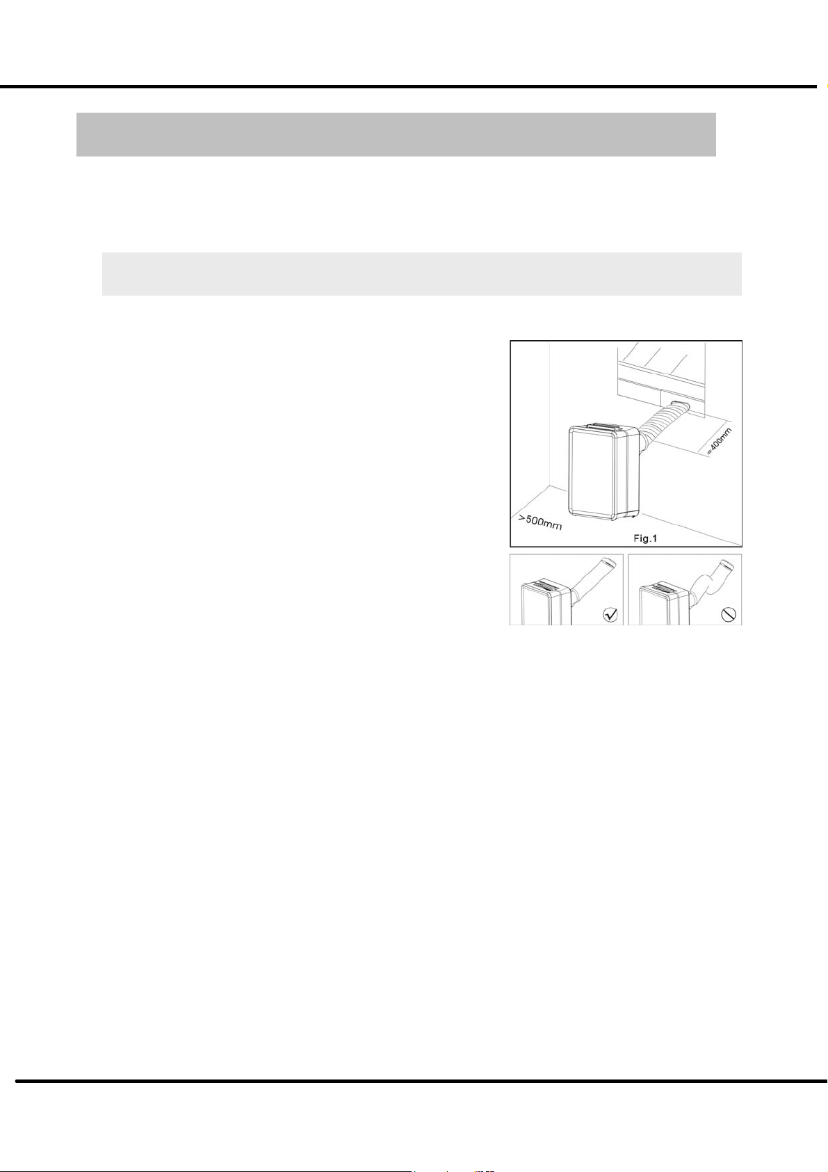
Installation
............................................................................................................................................
1
Caution
..................................................................................................................................................
1
Operational ...........................................................................................................................................
1
Attention …………………………………………………………………………………………...…2
Specification ..............................................................................................................................3
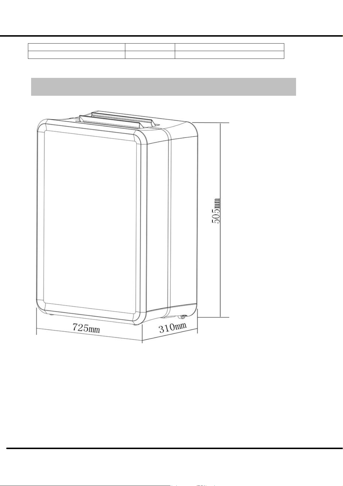
Out dimension ...........................................................................................................................5
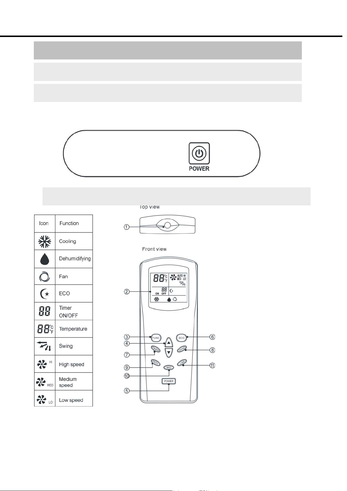
Control panel & Description of function ……………………………………………………6
LED
display...........................................................................................................................................
6
Power key …………………………………………………………………………………………….6
Remote control function refrigerant cycle ……………………………………………………………8
Refrigerant cycle diagram ……………………………………………………………………9
PCB drawing & wiring diagram ……………………………………………………………10
Unit Disassembly sequence .....................................................................................................12
Step1 Casing Disassembly
.............................................................................................................
12
Step2 Internal Parts Disassembly
..................................................................................................
14
Exploded ..................................................................................................................................15
Feature ………………………………………………………………………………………..18
Parts of the Air Conditioner
................................................................................................................
18
Accessories
........................................................................................................................................
18
Electronic function .................................................................................................................20
Function
..............................................................................................................................................
20
Controller Specifications
.......................................................................................................................
20
Controller Structure
...............................................................................................................................
20
Sensor Definitions
................................................................................................................................
20
Mode
...................................................................................................................................................
20
Sleep …………………………………………………………………………………………………...
21
Timer setting .......................................................................................................................................
21
Other controls
…………...…………………………………………………………………………….
22
Timer Setting ..
……………………………………………………………………………………….
22
Compressor delay protection Protection …...................................................................................................22
Sensor errors ……………………………………………………………………………………...22
Step Motor ………………………………………………………………………...…………………..22
Running signal indicator ………………………… …………………….……………………………..22
Power Button …………………………………………………………………………………………..23
Auto-restarting function ………………………………………………………………………………...23
Basic test procedure ................................................................................................................24
Defective compressor
........................................................................................................................
25
Sealed refrigeration system
r
e
pairs
....................................................................................................
25
Fan
motor............................................................................................................................................
27
Capacitor
.............................................................................................................................................
28
Characteristic of temperature sensor ....................................................................................29
Trouble shooting ......................................................................................................................30