Argo FCW01 Operating manual

FAN COIL UNIT WALL MOUNTED TYPE
USER AND INSTALLATION MANUAL
Read this manual carefully before installing and using the commercial air
conditioners and keep it for future reference.
If this manual is lost, consult the electronic version on the argoclima.com website.
Argoclima reserves the right to make any changes to this document due to possible
product improvements without prior notice.
V 11/20
INDOOR UNITS
FCW01
FCW02
FCW03
FCW04
22

To Users
Thank you for selecting Argoclima product. Please read this instruction manual carefully before
installing and using the product, so as to master and correctly use the product. In order to guide you
to correctly install and use our product and achieve expected operating effect, we hereby instruct as
below:
(1) This equipment should be installed, operated or maintained by the qualified servicemen who have had
specific training. During operation, all safety issues covered in the labels, User’s Manual and other
literature should be followed strictly. This equipment is not intended for use by persons (including
children) with reduced physical, sensory or mental capabilities, or lack of experience and knowledge,
unless they have been given supervision or instruction concerning use of the appliance by a person
responsibility for their safety. Children should be supervised to ensure that they do not play with the
appliance.
(2) This product has gone through strict inspection and operational test before leaving the factory. In order
to avoid damage due to improper disassembly and inspection, which may impact the normal operation
of unit, please do not disassemble the unit by yourself. You can contact with the special maintenance
center of our company if necessary.
(3) For personal injury or property loss and damage caused by improper operation such as improper
installation and debugging, unnecessary maintenance, violation of related national laws and rules and
industrial standard, and violation of this instruction manual, etc., we will bear no liability.
(4) When the product is faulted and cannot be operated, please contact with our maintenance center as
soon as possible by providing the following information.
yContents of nameplate of product (model, cooling/heating capacity, product No., ex-factory date). y
Malfunction status (specify the situations before and after the error occurs).
(5) All the illustrations and information in the instruction manual are only for reference. In order to make
the product better, we will continuously conduct improvement and innovation. We have the right to
make necessary revision to the product from time to time due to the reason of sales or production, and
reserve the right to revise the contents without further notice.
(6) The final right to interpret for this instruction manual belongs to Argoclima Spa.
23

Contents
Safety Notices (Please be sure to abide ) ............................................................ 25
1.
Product Introduction ............................................................................................29
1.1 Working Principle............................................................................................................ 29
1.2 Main Parts ...................................................................................................................... 29
1.3 Working Conditions .........................................................................................................30
2.
Installation Instructions .......................................................................................31
2.1 Installation Dimension Diagram...................................................................................... 31
2.2 Installation of the Rear Panel ..........................................................................................32
2.3 Piping Holes for Installation.............................................................................................32
2.4 Installation of the Drain Pipe ...........................................................................................32
2.5 Installation of the Connection Pipe..................................................................................33
2.6 Installation of the Water Damper.................................................................................... 34
2.7 Electric Wiring ................................................................................................................ 34
3.
Commissioning and Maintenance ......................................................................35
3.1 Inspection after Installation..............................................................................................35
3.2 Trial Operation.................................................................................................................35
3.3 Air Discharge .................................................................................................................. 36
3.4 Maintenance................................................................................................................... 36
4. Troubleshooting ................................................................................................. 39
4.1 Error List......................................................................................................................... 39
4.2 Error Codes .................................................................................................................... 41
24

Fan Coil Unit Wall Mounted Type
Safety Notices (Please be sure to abide )
WARNING: If not abide strictly, it may cause severe damage to the unit or the people.
NOTE: If not abide strictly, it may cause slight or medium damage to the unit or the people.
This sign indicates that the operation must be prohibited. Improper operation may cause severe
damage or death to people.
This sign indicates that the items must be observed. Improper operation may cause damage to
people or property.
WARNING
Please perform installation in
accordance with this manual
and read it carefully prior to
startup and service.
Installation should be done
by sales agents or qualified
servicemen. Do not do it
personally, as incorrect
installation would lead to water
leakage, electrocution, fire
hazards etc.
Before installation, check
for power supply and see if
it complies with that on the
nameplate. Besides, check for
safety of the power supply.
This unit should be grounded
and there should be grounding
lines for the power socket so
as to prevent electrocution. Do
not connect the grounding lines
to the gas lines, water lines,
lightning rod or telephone
lines.
Specialized
Fittings
Specialized components
and parts should be used
for installation; otherwise it
would lead to water leakage,
electrocution, re hazards etc.
Specialized
Size of the power lines should
be large enough. Power lines
and other electric connection
lines should be replaced by
specialized cables.
When wiring of power lines is
nished, remember to install a
electric box to prevent safety
accidents.
When installation is finished,
check for connection of drain
lines, water lines and electric
lines, as incorrect connection
would lead to water leakage,
electrocution, re hazards etc.
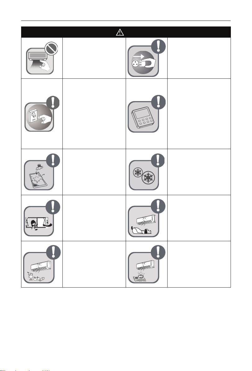
Do not start or stop the unit by
drawing out or plugging in the
power plug.
Do not let the children play
with this unit.
Do not operate this unit with
wet hands.
Do not clean this unit until the
unit is turn off and the power
supply is cut off, otherwise it
would lead to electrocution or
personal injury.
25

Fan Coil Unit Wall Mounted Type
WARNING
Do not spray or rinse this unit
with water, as it would lead to
malfunction or electrocution.
Do not let this unit exposed
to moist, wet or corrosive
environment.
Volatile liquid like thinner or
petroleum would damage
appearance of this unit. (Only
soft dry cloth and cloth with
neutral detergent can be used
to clean the outer casing of
this unit.)
Do not make the set point too
low under the cooling mode.
Entering and leaving water
lines, condensate lines and
valves should be thermal
insulated so as to prevent from
dewing in summer.
Do not repair this unit by
yourself, as incorrect repair
would lead to electrocution or
fire hazards. Please contact
Argoclima after-sales center
and repair should be done
by the qualified servicemen.
Never splice the power cord or
use an extended cord.
It can cause overheating or
re.
Don’t insert your hands or stick
into the air intake or outlet
vents.
Don't block the air intake
of the FCU.It can decrease
the FCU capacity or cause a
malfunction.
Keep combustilble spray away
from the units more than 1.5m.
It can cause a re or explosion.
26

Fan Coil Unit Wall Mounted Type
NOTE
During operation, do not insert
fingers or other objects into
the moving parts, which would
lead to unnecessary injuries.
Please cut off the power supply
when this unit is not used for
long time in consideration of
safety.
When there is something
unusual (like unusual smell,
burning smell, smoke etc.),
please turn off the unit and cut
off the main power supply at
once, and then contact
Argoclima after-sales
servicemen. If unusual
conditions go on, this unit
would burn out, or even it would
lead to electrocution or fire
hazards.
Wiring of power lines and
electric connection lines should
be secure enough. Terminals
also should be tightly fastened.
The connection line should
not suffer external forces. For
the unit equipped with the
wired controller, the controller
would be powered on firstly;
otherwise it would be out of
normal use.
The filter should be cleaned
periodically in case that heat
exchanging effect would be
affected.
Please do freeze protection in
winter to prevent copper tubes
from cracking.
Don’ t leave windows and
doors open for a long time
while operating the FCU. It can
decrease the FCU capacity.
Don’t blow the wind to animals
and plants directly. It can
cause a bad inuence to them.
Don’t use the FCU for other
purposes, such as drying
clothes, preserving foods, etc.
Don’t place a space heater
near the FCU.
27

Fan Coil Unit Wall Mounted Type
This appliance is intended to be used by expert or trained users in shops, in light industry and on farms,
or for commercial or household use by lay persons.
Installing the unit in the following places may cause malfunction. If it is unavoidable,please consult the
local dealer:
(1) The place with strong heat sources,vapors, ammable or explosive gas,or volatile objects spread in the
air.
(2) The place with high-frequency devices (such as welding machine,medical equipment).
(3) The place near coast area.
(4) The place with oil or fumes in the air.
(5) The place with sulfureted gas.
(6) Other places with special circumstances.
(7) Do not use the unit in the immediate surroundings of a laundry, a bath, a shower or a swimming pool.
DISPOSAL: This marking indicates that this product should not be disposed with other
household wastes throughout the EU. To prevent possible harm to the environment or human
health from uncontrolled waste disposal, recycle it responsibly to promote the sustainable
reuse of material resources. To return your used device, please use the return and collection
systems or contact the retailer where the product was purchased. They can take this product
for environmental safe recycling.
This appliance can be used by children aged from 8 years
and above and persons with reduced physical, sensory or
mental capabilities or lack of experience and knowledge if
they have been given supervision or instruction concerning
use of the appliance in a safe way and understand the
hazards involved.Children shall not play with the appliance.
Cleaning and user maintenance shall not be made by
children without supervision.
28

Fan Coil Unit Wall Mounted Type
1. Product Introduction
1.1 Working Principle
The cold (hot) water entering the heat exchanger will do heat exchanging with air passing through the
surface of the heat exchanger to condition the air temperature and humidity. There is no (cold) hot source
for this product itself. The running mode depends on the environment temperature and the running mode of
the main unit.
Protection against hot air
Under the cooling mode, when the water temperature is too high, the fan will be stopped to avoid the
unit from blowing out hot air.
Protection against cold air
Under the heating mode, when the water temperature is too low, the fan will be stopped to avoid the unit
from blowing out cold air.
Memory function
Upon power failure, some statuses can be memorized, including: mode setting, fan speed setting, fan
swing setting, temperature setting etc.
1.2 Main Parts
Fig. 1
29

Fan Coil Unit Wall Mounted Type
1.3 Working Conditions
(1) The entering water temperature for cooling is suggested to be no less than 5℃,otherwise it woule lead
to condensate; the entering water temperature for heating is suggested to be not higher than 60 ℃,
otherwise it would lead to corrosion of copper tubes or abnormal noise.
(2) The suggested working environment temperature for cooling ranges 16 ~40℃and ranges 10 ~30℃
for heating. Beside, the relative humidity is or less than 80%.
(3) This product is a kind of comfort air conditioning, and is not allowed to be installed where there are
corrosive, explosive and inammable substances or smog; otherwise it would lead to operation failure,
shortened service life, ve hazard or even severe injuries. Special air conditions are required for where
mentioned above.
(4) The A-weighted sound pressure level is below 70dB.
(5) The temperature exchange efciency and enthalpy exchange efciency are tested under these testing
conditions as below:
yCooling capacity: air 27°C DB , 19°C WB, water temperature intake 7°C, outlet 12°C.
yHeating capacity: air 20°C DB , For the tow-row coils applicable to EU, the entering/leaving water
temperature is 45°C and 40°C; and for the four-row coils, the entering/leaving water temperature is
65°C/55°C.
yFreeze-up : air 27°C DB, 24°C WB , water temperature 6°C intake , 10°C outlet .
ySound power level according to ISO 5151. Sound pressure level are calculated at the below of air-
outlet 1m and 1m distance. The noise are tested before leaving factory.
30

Fan Coil Unit Wall Mounted Type
2. Installation Instructions
2.1 Installation Dimension Diagram
structures.
50cm
30cm
Fig.2
2.2 Installation of the Rear Panel
(1) Always mount the rear panel horizontally. Due to the water tray of the unit has been adopted the both-
way drainage design, the outlet of water tray should be adjusted slightly down when installing, that is
to take the outlet of the water tray as the center of a circle, the included angle between the evaporator
and level should be 0 or more, that is good for condensing water drainage.
31

Fan Coil Unit Wall Mounted Type
Fig.3
(2) Fix the rear panel on the wall with screws. (Where is pre-covered with plastic granula)
(3) Be sure that the rear panel has been xed rmly enough to withstand the weight of an adult of 60kg,
further more, the weight should be evenly shared by each screw.
2.3 Piping Holes for Installation
(1) Make the piping hole (Ф55) in the wall at a slight downward slant to the outdoor side.
(2) Insert the piping-hole sleeve into the hole to prevent the connection piping from being damaged when
passing through the hole.
55
Indoor Outdoor
Wall pipe
Seal pad
Fig. 4
2.4 Installation of the Drain Pipe
(1) For smooth draining, the drain hose should be placed at a downward slant.
(2) Do not wrench or bend the drain hose or ood its end by water.
(3) When the long drainage hose passing through indoor,should wrap the insulation materials.
Fig. 5
2.4.1 The piping can be lead out from left, left rear.
(1) When routing the piping and wiring from the left side of the unit, cut off the tailings from the chassis in
necessary (as shown in Fig.6).
yCut off the tailings 1 when routing the wiring only;
yCut off the tailings 1 and tailings 2 when routing both the wiring and piping.
(2) Take out the piping from body case, wrap the piping electric wire, water pipe with tape and pull them
through the piping hole (as shown in Fig.7).
(3) Hange the mounting slots of the FCU on the upper tabs of the rear panel and check if it is rm enough
(as show in Fig.8).
32

Fan Coil Unit Wall Mounted Type
Inlet water side pipe
Inlet side piping
Finally wrapit
with tape Water drainage pipe
Outlet water side
Outlet side
piping insulation
Fig.6
Fixing hook
Mounting
p
late
Mounting
baord
Fig.7
Left rear
Left
Fig.8
Tailing2
Tailing1
2.5 Installation of the Connection Pipe
(1) Align the center of the piping pipe with the relevant valve.
(2) Place the nut, spring washer, washer, O-ring cross the pipe sequentially, and keep them tightly close to
each other with a distance of 6-7mm from the O-ring to the pipe end.
(3) Screw in the pipe nut by hand and then tighten the nut with spanner.
(4) If supplied by the manufacturer, the connection pipe shall be installed in place so as to guarantee the
reliable connection.
FCU pipe O-ring
Spanner Torque wrench
O-ring
Washer
Washer
Spring washer
Spring washer
Nut
Nut
Connection pipe
Connection nut
Fig. 9
NOTE
Firstly connect the connection pipe to the FCU pipe, then to the connection pipe; pay attention
to the piping bending, do not damage the connection pipe; the joint nut couldn't tighten too much,
otherwise it may cause leakage.
33

Fan Coil Unit Wall Mounted Type
FCU pipe
O-ring
O-ring
Before installed the two pipes must be
tightened with the steps of the connection nut.
Be sure there is an
interval of 6-7mm when
the fitting is completed.
Be sure there is an
interval of 6-7mm when
the fitting is completed.
Washer
Washer
Spring washer
Spring washer
Nut
Nut
Connection pipe
Connection nut
Fig. 10
2.6 Installation of the Water Damper
All units must be equipped with a motorized valve because of the following main reasons.
(1) There would be a water ood risk for some units without motorized valves in the event that they stop
under the cooling conditions.
(2) Under the cooling and heating conditions, energy loss would happen to the chilled water and hot water.
Notes:
(a) The pipe must be wrapped by heat insulation material to prevent condensing water drips.
(b) It is prohibited to bind directly the water valve wire and sponge up with the copper tube, as there would
be probably a short circuit or even electric leakage. The right way is letting the water valve wire go
through the pipe sleeve and then binding the sponge and pipe sleeve.
(c) It is prohibited to put the valve core upside down.
2.7 Electric Wiring
2.7.1 Safety Precautions for Electric Appliances
(1) A dedicated power supply circuit should be used in accordance with local electrical safety regulations.
(2) Don't drag the power cord with excessive force.
(3) The unit should be reliably earthed and connected to an exclusive earth device by the professionals.
(4) The air switch must have the functions of magnetic tripping and heat tripping to prevent short circuit
and overload.
(5) The minimum distance between the unit and combustive surface is 1.5m.
(6) The appliance shall be installed in accordance with national wiring regulations.
(7) An all-pole disconnection switch with a contact separation of at least 3mm in all poles should be
connected in xed wiring.
NOTE
• Make sure the live wire, neutral wire and earth wire in the family power socket are properly connected.
There should be reliable circuit in the diagram.
• Inadequate or incorrect electrical connections may cause electric shock or re.
2.7.2 Earthing Requirements
(1) The FCU is type Ⅰelectric appliance. Please ensure that the unit is reliably earthed.
(2) The yellow-green wire in air conditioner is the earthing wire which can not be used for other purposes.
Improper earthing may cause electric shock.
(3) The earth resistance should accord to the national criterion.
34

Fan Coil Unit Wall Mounted Type
(4) The power must have reliable earthing terminal. Please do not connect the earthingwire with the
following:
①Water pipe ②Gas pipe ③Contamination pipe ④Other place that professional personnel
consider is unreliable
(5) The model and rated values of fuses should accord with the silk print on fuse cover or related PCB.
2.7.3 Connection of the electric wire
When connecting the electric wire if the wire length is not enough, please contact with the authorized
service shop to buy a exclusive electric wire that is long enough and the joint on the wire are not allowed.
(1) The electric wiring must be correctly connected, wrong connection may cause spare parts malfunction.
(2) Tighten the terminal screw in order to prevent loose.
(3) After tighten the screw, slight pull the wire and conrm whether is it rm or not.
(4) If the earth wire is wrong connection, that may cause electric shock.
(5) The cover plate must be xed, and tighten the connection wire, if it is poor installed, that the dust,
moisture may enter in or the connection terminal will be affected by outside force, and will cause re or
electric shock.
3. Commissioning and Maintenance
3.1 Inspection after Installation
Items to be checked Possible malfunction
Has it been xed rmly? The unit may drop,shake or emit noise.
Have you done the water leakage test? It may cause insufcient cooling (heating) capacity.
Is heat insulation sufcient? It may cause condensation and dripping.
Is water drainage well? It may cause condensation and dripping.
Is the voltage in accordance with the rated voltage
marked on the nameplate? It may cause electric malfunction or damage the part.
Is the electric wiring and piping connection installed
correctly and securely? It may cause electric malfunction or damage the part.
Has the unit been connected to a secure earth
connection? It may cause electrical leakage.
Is the power cord specied? It may cause electric malfunction or damage the part.
Is the inlet and outlet been covered? It may cause insufcient cooling(heating)capacity.
3.2 Trial Operation
3.2.1 Before Trial Operation
(1) Do not switch on power before installation is nished completely.
(2) Electric wiring must be connected correctly and securely.
(3) All the impurities such as scraps and thrums must be cleared from the unit.
3.2.2 Trial Operation Steps
(1) Switch on power, pressing "ON/OFF" button on the wireless remote control to start the test mode.
(2) Press TURBO button no less than 3 times during 5 seconds. The FCU run at test mode.
35

Fan Coil Unit Wall Mounted Type
(3) Using the controller, the FCU can select the COOL, HEAT, FAN, DRY to check whether the operation
is normal or not.
(4) Leave test mode to pressing "ON/OFF" button on the controller.
(5) During 5 minute, the FCU would leave test mode automatically without pressing any button.
(6) Switch off the FCU, pressing "ON/OFF" button on the controller.
3.3 Air Discharge
If it is necessary to discharge air, follow the steps below.
(1) Remove the screw.
Srew
(2) Remove the plastic cover.
Plastic cover
Valve plug
(3) Turn the valve plug anticlockwise three or four circles (shown as the ON direction on the plate).
Valve plug
(4) Start the fan coil unit up.
Turn the valve plug clockwise to tight (shown as the OFF direction on the plate). Fix the plastic cover
with the screw.
3.4 Maintenance
3.4.1 Emergency Operation
When the wireless remote control is lost or damaged, please use the AUTO button. At this time, sketch
map for changing batteries cassette type fan coil unit 9 the unit will operated as follow:
(1) At operation: When the unit stop, press AUTO button over 5 seconds to start the unit.
(2) At stopping: When the unit is running, press AUTO button and overrun 5 seconds to stop the unit.
(3) When the unit is running, press AUTO button less than 5 seconds. The unit select from COOL, DRY,
FAN, HEAT, COOL modes automatically.
36

Fan Coil Unit Wall Mounted Type
Open the front panel, the manual switch is on the edge as Fig.11.
Manual switch
Fig.11
3.4.2 Care and Cleaning
NOTE
• Turn power off and pull out the power plug before cleaning air conditioner, or it may cause electric
shock.
• Never sprinkle water on the unit for cleaning because it can cause an electric shock.
• Volatile liquid (e.g. thinner or gasoline) will damage the air conditioner. (So wipe the units with a dry
soft cloth, or a cloth slightly moistened with water or cleanser.)
(1) Cleaning the front panel
When cleaning the front panel, please dip the cloth into the water temperature of 45°C below, then to
dry the cloth and wipe the dirty part.
(2) Cleaning the air tler (Recommended once every three months)
NOTE
If dust is much more around the air conditioner, the air lters should be cleaned many times. After
taking off the lter, don't touch the n of the unit, in order to avoid hurt your ngers.
yTake down the air lter
At the slot of surface panel to open an angle, pull the air lter downward and take it out, please see the
Fig. 12(a, b).
Fig.12
yClean the air lter
To clean the dust adhering to the lters, you can either use a vacuum cleaner, or wash them with warm
water the water with the neutral detergent (below 45°C) , and dry it in the shade.
NOTE
Never use water above 45°C to clean, or it can cause deformation or discoloration. Never parch it by
re, or can cause a re or deformation.
37

Fan Coil Unit Wall Mounted Type
14
yReinstall the air lter
Reinsert the lters along the direction of arrowhead, and then to cover the cover and clasp it.
Fig.13
Fig.14
3.4.3 Installation and Maintenance of Healthy Filter (optional)
◆Installation Instructions
(1) Forcibly pull the panel for a specic angle from the two ends of the front panel according to the arrow
direction. Then pull the air lter downwards to remove it. (See Fig.15.)
(2) Mount the healthy lter onto the air lter, (as shown in Fig.16). If the air lter cannot be installed,please
mount the healthy lter on the front case (as shown in Fig.17).
(3) Mount the air lter properly along the arrow direction in Fig.18, and then close the panel cover.
◆Cleaning and Maintenance.
Take out the healthy filter before cleaning and reinstall it after cleaning according to the installation
instruction. Pay special attention that silver ion filter can't be cleaned with water, while active carbon,
photocatalyst, low temperature conversion (LTC) catalyst, formaldehyde eliminator, catechin or mite killing
lter can, but can't with brush or hard things. Dry it in the shade or sun after cleaning, but not by wiping.
◆ Service Life
(1) The healthy lter commonly has its usage lifetime for one year under normal condition. As for silver ion
lter, it is invalid when its surface becomes black (green).
(2) This supplementary instruction is provided for reference to the unit with healthy lter. If the graphics
provided herein is different from the physical goods, the latter one shall prevail. The quantity of healthy
lters shall be based on the actual delivery.
38

Fan Coil Unit Wall Mounted Type
Fig.15 Fig.16
Fig.17 Fig.18
4. Troubleshooting
4.1 Error List
CAUTION
The FCU is not expected to be serviced by users. Incorrect repair may cause electric shock or re,
so please contact an authorized service center for professional service. The following checks prior to
contact may save your time and money.
Phenomenon Troubleshooting
The unit does not operate:
•Blow of fuse or breaker
•Power cut
•Don’t connect with power
• Low batteries of wireless remote controller
•Wireless remote controller exceed remote control area
Odours are emitted:
•Some odours may be emitted from the FCU. This is
the result of room smells (such as furniture, tobacco,
ect.) which have been taken into the FCU.
•Consult authorized service center for cleaning if the
odours still exist.
Mist is emitted in COOL mode
During cooling operation, a thin mist may be seen
emitted from the FCU due to high room temperature and
humidity.After a period of time, the mist will disappear
with the decrease of room temperature and humidity.
39

Fan Coil Unit Wall Mounted Type
Phenomenon Troubleshooting
Cracking noise:
•This is the sound of friction caused by expansion and/
or contraction of panel or other parts due to the change
of temperature.
The unit can not be started up:
Breaking off
• Is the power cut off?
• Is the power plug loose? (If applicable )
• Is the circuit protection device tripped off?
• Is voltage higher or lower?(Tested by professionals)
• Is the TIMER correctly used?
Cooling/Heating effect is poor: • Is temperature setting appropriate?
• Is the inlet or outlet blocked?
• Is the lter dirty?
• Is the window or the door open?
• Is low fan speed set?
• Are there heat sources in the room?
Remote controller is not available: •Check if there is magnetic or electrical interference
near the unit that may affecting operation of the
controller. In this case, pull the plug out and reinsert it.
•Is the remote controller within its operating range or
obstructed? Check the condition of the batteries and
replace them if necessary.
•Check if the remote controller is damaged.
Water leakage of FCU.
•The humidity is high.
• Condensate overows.
•Drain hose is loose.
Noise from FCU. The noise emitted when the fan is switching on or off.
FCU can not blow air:
•In HEAT mode, when the temperature of FCU heat
exchanger is very low, air flow is stopped in order to
prevent cold air.
•In COOL mode, when the temperature of FCU heat
exchanger is very high, air flow is stopped in order to
prevent hot air.
Moisture on air outlet :
If the unit operates at high humidity for a long time,
moisture will be generated onthe air outlet grill and then
drip off.
C5:Malfunction of connector jumper:
Check if the connector jumper contacts properly. If the
PCB is to be replaced, please take off the old for the
new PCB.
40

Fan Coil Unit Wall Mounted Type
Phenomenon Troubleshooting
F0:Malfunction of the ambient temperature sensor Check if the room temperature sensor is connected
properly
F1:Malfunction of evaporator temperature sensor Check if the evaporator temperature is connected
properly.
If any one of the following situations occurs, immediately stop all operations,cut off the power
supply, and contact the authorized personnel.
4.2 Error Codes
Error Codes Error Description
F0 Indoor unit main board environment temperature sensor error
F1 Cooler pipe temperature sensor error
F5 Control panel ambient temperature sensor error
H6 PG motor stalling protection
C5 Jumper error
E6 Communication error
www.argoclima.com
41
This manual suits for next models
3
Table of contents
Other Argo Air Conditioner manuals

Argo
Argo AE4MI91AH Operating manual

Argo
Argo Argoclima Magico User manual

Argo
Argo AE2MI40AH Operating manual

Argo
Argo CHARM 9000 UI User manual

Argo
Argo XFETTO DCI HPL User manual

Argo
Argo DSAV92R5TAA Manual

Argo
Argo AEG ECO PLUS 35PIH User manual

Argo
Argo IRO User manual

Argo
Argo AMG21SDT Manual

Argo
Argo ODIN PLUS User manual