Argo AWMI28AHL User manual

85264189909000
COOL/DRY/HEAT Model
Indoor unit A
Indoor unit B
Indoor unit C
Indoor unit D
Outdoor unit
Combination example
This air conditioner uses the new refrigerant R410A.
Contents Page
IMPORTANT!
Please Read Before Starting .................................. 1
1. GENERAL.......................................................... 2
1-1. Tools Required for Installation (not supplied)
1-2. Accessories Supplied with Unit
1-3. Optional Copper T ubing Kit
1-4. Type of Copper T ube and Insulation Material
1-5. Additional Materials Required for Installation
2. INSTALLATION SITE SELECTION ................... 3
2-1. Indoor Unit
2-2. Outdoor Unit
2-3. Outer Dimensions of Outdoor Unit
2-4. Diagram of Outdoor Unit Installation
3. INSTALLATION PROCESS ................................ 7
3-1. Embedding the T ubing and Wiring
3-2. Installing Outdoor Unit
3-3. Use of the Flaring Method
3-4. Flaring Procedure with a Flare T ool
3-5. Caution before Connecting T ubes Tightly
3-6. Tubing Connections
3-7. Insulation of Refrigerant T ubing
3-8. Taping the T ubes
3-9. Finishing the Installation
3-10. Refrigerant Operation System
4. AIR PURGING................................................... 11
■Air Purging with a V acuum Pump (for T est Run)
■Pump-Down
5. WIRING INSTRUCTIONS ................................ 14
5-1. General Precautions on Wiring
5-2. Recommended Wire Length and Diameter
5-3. Wiring System Diagram
5-4. Electric Wiring Diagram
5-5. How to Connect Wiring to the T erminal
5-6. Wiring Instructions for the Outdoor Unit
6. TEST RUN......................................................... 21
7. INSTALLATION CHECK SHEET ...................... 22
Model Combinations
Indoor Units
AWMI28AHL
AWMI36AHL
AWMI50AHL
AWMI70AHL
Outdoor Unit
AE4MI91AH
Combine indoor and outdoor units only as listed in
the combination tables for the 4-room outdoor unit
as shown in its respective manual.
Power Source:
50 Hz, single-phase, 220-240 V
60 Hz, single-phase, 220 V
INSTALLATION INSTRUCTIONS
- Multi Split system air conditioner -
02/2004

1
IMPORTANT!
Please Read Before Starting
This air conditioning system meets strict safety and oper-
ating standards. As the installer or service person, it is an
important part of your job to install or service the system
so it operates safely and efficiently.
For safe installation and trouble-free operation, you
must:
●Carefully read this instruction booklet before beginning.
●Follow each installation or repair step exactly as
shown.
●Observe all local, state, and national electrical codes.
●Pay close attention to all warning and caution notices
given in this manual. This symbol refers to a hazard
or unsafe practice which can
result in severe personal injury
or death.
This symbol refers to a hazard
or unsafe practice which can
result in personal injury or
product or property damage.
If Necessary, Get Help
These instructions are all you need for most installation
sites and maintenance conditions. If you require help for
a special problem, contact our sales/service outlet or
your certified dealer for additional instructions.
In Case of Improper Installation
The manufacturer shall in no way be responsible for
improper installation or maintenance service, including
failure to follow the instructions in this document.
SPECIAL PRECAUTIONS
When Wiring
ELECTRICAL SHOCK CAN CAUSE
SEVERE PERSONAL INJURY OR DEATH.
ONLY A QUALIFIED, EXPERIENCED
ELECTRICIAN SHOULD ATTEMPT TO
WIRE THIS SYSTEM.
• Do not supply power to the unit until all wiring and tub-
ing are completed or reconnected and checked.
• Highly dangerous electrical voltages are used in this
system. Carefully refer to the wiring diagram and
these instructions when wiring. Improper connections
and inadequate grounding can cause accidental
injury or death.
• Ground the unit following local electrical codes.
• Connect all wiring tightly. Loose wiring may cause
overheating at connection points and a possible fire
hazard.
When Transporting
Be careful when picking up and moving the indoor and
outdoor units. Get a partner to help, and bend your
knees when lifting to reduce strain on your back. Sharp
edges or thin aluminum fins on the air conditioner can
cut your fingers.
When Installing…
…In a Ceiling or Wall
Make sure the ceiling/wall is strong enough to hold the
unit’s weight. It may be necessary to construct a strong
wood or metal frame to provide added support.
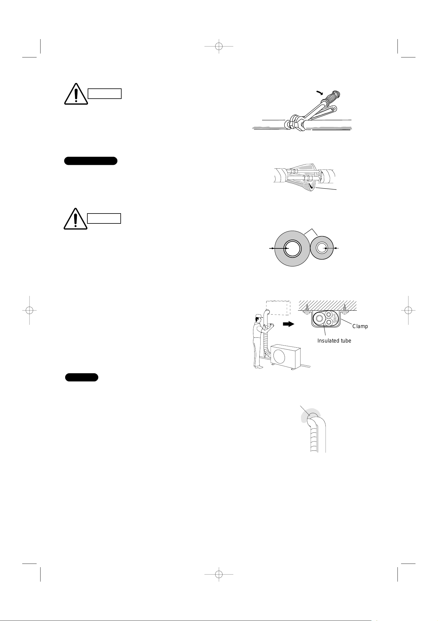
…In a Room
Properly insulate any tubing run inside a room to prevent
“sweating” that can cause dripping and water damage to
walls and floors.
…In Moist or Uneven Locations
Use a raised concrete pad or concrete blocks to provide
a solid, level foundation for the outdoor unit. This pre-
vents water damage and abnormal vibration.
…In an Area with High Winds
Securely anchor the outdoor unit down with bolts and a
metal frame. Provide a suitable air baffle.
…In a Snowy Area (for Heat Pump-type Systems)
Install the outdoor unit on a raised platform that is higher
than drifting snow. Provide snow vents.
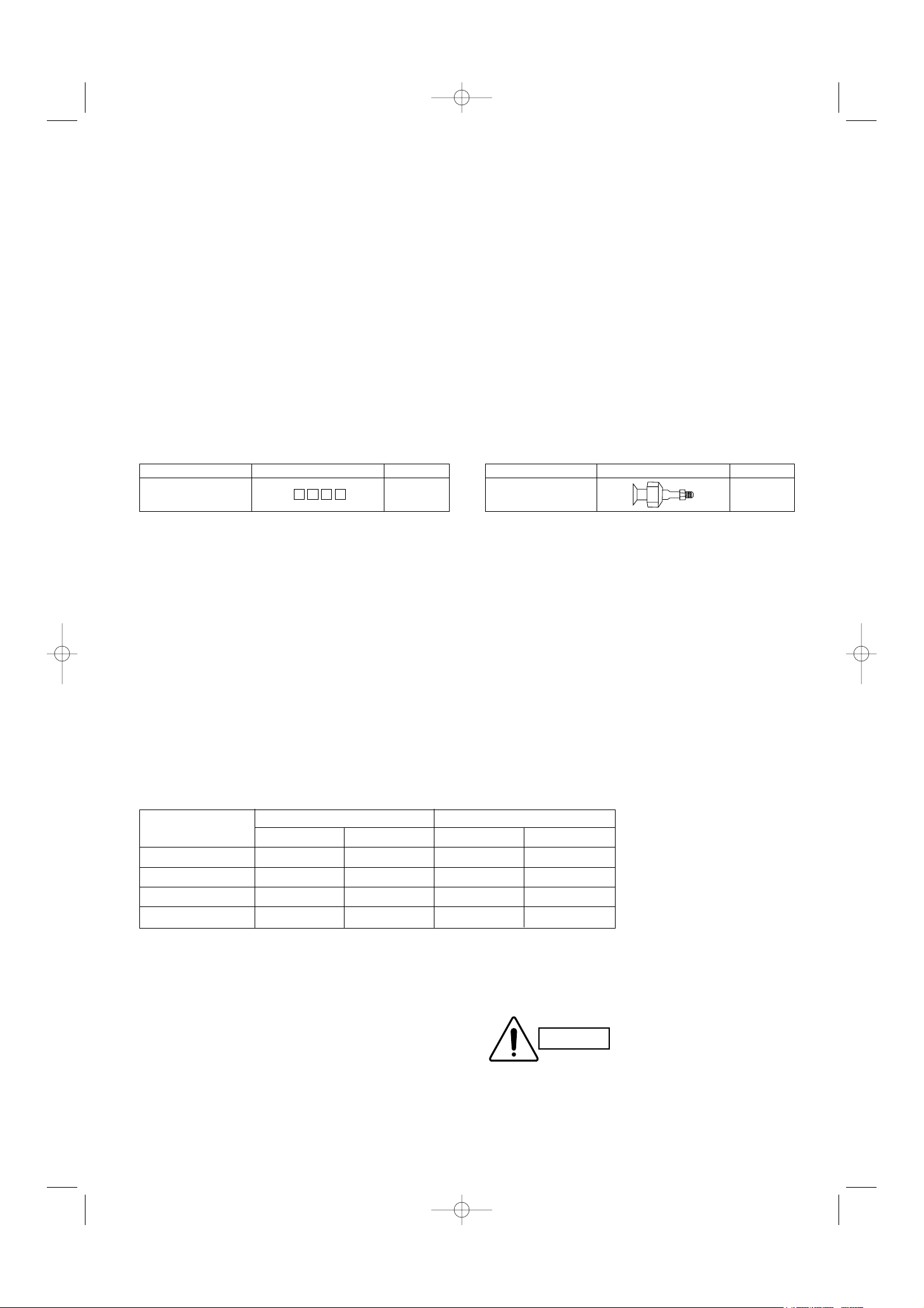
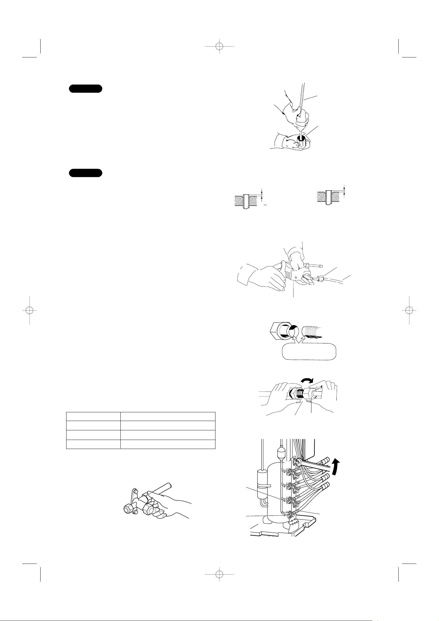
When Connecting Refrigerant Tubing
• Use the flare method for connecting tubing.
• Apply refrigerant lubricant to the matching surfaces of
the flare and union tubes before connecting them,
then tighten the nut with a torque wrench for a leak-
free connection.
• Check carefully for leaks before starting the test run.
When Servicing
• Turn the power OFF at the main power box (mains)
before opening the unit to check or repair electrical
parts and wiring.
• Keep your fingers and clothing away from any moving
parts.
• Clean up the site after you finish, remembering to
check that no metal scraps or bits of wiring have been
left inside the unit being serviced.
Others
• Ventilate any enclosed areas when installing or testing
the refrigeration system. Escaped refrigerant gas, on
contact with fire or heat, can produce dangerously
toxic gas.
• Confirm upon completing installation that no refriger-
ant gas is leaking. If escaped gas comes in contact
with a stove, gas water heater, electric room heater or
other heat source, it can produce dangerously toxic
gas.
• Do not install only a single indoor unit.
WARNING
WARNING
CAUTION
CAUTION

2
1. General
This booklet briefly outlines where and how to install
the air conditioning system. Please read over the
entire set of instructions for the indoor and outdoor
units and make sure all accessory parts listed are with
the system before beginning.
1-1. Tools Required for Installation (not supplied)
1. Standard screwdriver
2. Phillips head screwdriver
3. Knife or wire stripper
4. Tape measure
5. Carpenter’s level
6. Sabre saw or key hole saw
7. Hacksaw
8. Core bits
9. Hammer
10. Drill
11. Tube cutter
12. Tube flaring tool
13. Torque wrench
14. Adjustable wrench
15. Reamer (for deburring)
16. Vacuum pump (For R410A)
17. Manifold valve
1-2. Accessories Supplied with Unit
Table 1
1-3. Optional Copper Tubing Kit
Copper tubing for connecting the outdoor unit to the
indoor unit is available in kits which contain the narrow
and wide tubing, fittings and insulation. Consult your
nearest sales outlet or A/C workshop.
1-4. Type of Copper Tube and Insulation Material
If you wish to purchase these materials separately
from a local source, you will need:
(1) Deoxidized annealed copper tube for refrigerant
tubing as detailed in Table 2.
Cut each tube to the appropriate lengths +30 cm
to 40 cm to dampen vibration between units.
Table 2
(2) Foamed polyethylene insulation for the specified
copper tubes as required to precise length of tub-
ing. Wall thickness of the insulation should be not
less than 8 mm.
(3) Use insulated copper wire for field wiring.
Wire size varies with the total length of wiring.
Refer to 5. Wiring Instructions for details.
CAUTION
Check local electrical codes
and regulations before
obtaining wire. Also, check
any specified instructions or
limitations.
Parts Figure Q’ty
Labels for inter-unit A B C D 4 each
cable and tube
Model Narrow Tube Wide Tube
Outer Dia. Thickness Outer Dia. Thickness
AWMI28AHL 6.35 mm 0.8 mm 9.52 mm 0.8 mm
AWMI36AHL 6.35 mm 0.8 mm 9.52 mm 0.8 mm
AWMI50AHL 6.35 mm 0.8 mm 9.52 mm 0.8 mm
AWMI70AHL 6.35 mm 0.8 mm 12.7 mm 1.0 mm
Parts Figure Q’ty
Reducer 1

3
1-5. Additional Materials Required for Installation
(1) Refrigeration (armored) tape
(2) Insulated staples or clamps for connecting wire
(See local codes)
(3) Putty
(4) Refrigeration lubricant
(5) Clamps or saddles to secure refrigerant tubing
2. Installation Site Selection
2-1. Indoor Unit
AVOID:
●direct sunlight.
●nearby heat sources that may affect performance of the
unit.
●areas where leakage of flammable gas may be expected.
●places where large amounts of oil mist exist.
DO:
●select an appropriate position from which every corner of
the room can be uniformly cooled.
●select a location that will hold the weight of the unit.
●select a location where tubing and drain hose have the
shortest run to the outside.
●allow room for operation and maintenance as well as
unrestricted air flow around the unit.
●install the unit within the maximum elevation difference
(H1, H2, H3, H4) above or below the outdoor unit and
within a total tubing length (L1+L2+L3+L4) from the out-
door unit as detailed in Table 3 and Fig. 1.
Table 3
INDOOR
UNIT (1)
INDOOR
UNIT (4)
INDOOR
UNIT (3)
INDOOR
UNIT (2)
Tubing length (L1)
L2
L3
L4
Elevation
difference (H1) H2
H3
H4
OUTDOOR
UNIT
Fig. 1
WARNING
To prevent abnormal heat genera-
tion and the possibility of fire, do
not place obstacles, enclosures
and grilles in front of or sur-
rounding the air conditioner in a
way that may block air flow.
Max. Allowable Tubing Limit of Total Tubing Limit of Elevation
Model Length at Shipment Length (m) Difference (H1, H2, H3, H4)
(m) (m)
AE4MI91AH 30 70 (L1+L2+L3+L4) 10
This outdoor unit requires no refrigerant charge up to the maximum limit for total tubing
length of 70 m.
Therefore, no refrigerant needs to be added on-site.
NOTE

4
In the case below, a joint for connecting tubes of different sizes is needed when connecting the inter-unit tube (φ9.52)
to the outdoor unit valve (φ12.7).
φ6.35
φ6.35
φ6.35
φ6.35
φ9.52
φ9.52
φ9.52
φ9.52
φ9.52
A
φ9.52
B
φ9.52
C
Outdoor unit Indoor unit
Union φ9.52
Flare φ12.7
φ12.7
D
(φ12.7 → φ9.52) Supplied Reducer
(28 36 types)
(28 36 types)
(28 36 types)
(28 36 types)
(1) Connecting indoor unit types 28 to 36 at D
φ6.35
φ6.35
φ6.35
φ6.35
φ9.52
φ9.52
φ9.52
φ9.52
φ12.7
A
φ9.52
B
φ9.52
C
Outdoor unit Indoor unit
Union φ12.7 Flare φ9.52
φ12.7
D
(28 36 types)
(28 36 types)
(28 36 types)
(50 type)
(More than 17 m)
(2) Connecting indoor unit type 50 at D (Length of tube: more than 17 m)
φ6.35
φ6.35
φ6.35
φ6.35
φ9.52
φ9.52
φ9.52
φ9.52
φ9.52
A
φ9.52
B
φ9.52
C
Outdoor unit Indoor unit
Union φ9.52
Flare φ12.7
φ12.7
D
(φ12.7 → φ9.52) Supplied Reducer
(28 36 types)
(28 36 types)
(28 36 types)
(50 type)
(3) Connecting indoor unit type 50 at D (Length of tube: less than 17 m)
φ6.35
φ6.35
φ6.35
φ6.35
φ9.52
φ9.52
φ9.52
φ9.52
φ12.7
A
φ9.52
B
φ9.52
C
Outdoor unit Indoor unit
φ12.7
D
(28 36 types)
(28 36 types)
(28 36 types)
(70 type)
(4) Connecting indoor unit type 70 at D
Fig. 2a
Fig. 2b
Fig. 2c
Fig. 2d

5
2-2. Outdoor Unit
AVOID:
●heat sources, exhaust fans, etc. (Fig. 3)
●damp, humid or uneven locations.
DO:
●choose a place as cool as possible.
●choose a place that is well ventilated.
●allow enough room around the unit for air intake/
exhaust and possible maintenance. (Fig. 4a)
●provide a solid base (level concrete pad, concrete
block, 15 ×40 cm beams or equal), a minimum of
15 cm above ground level to reduce humidity and
protect the unit against possible water damage and
decreased service life. (Fig. 4a)
●install cushion rubber (not provided) under unit’s
feet to reduce vibration and noise. (Fig. 4b)
●use lug bolts or equal to bolt down unit, reducing
vibration and noise.
●select a location where the operating noise and air
blowing from the outdoor unit will not disturb neigh-
bors.
●select a location where the clearance indicated by
⇔ in the installation diagram is ensured for the
front, rear, left, and right of the main unit.
●install so that the unit is level.
●select a location that can fully support the weight of
the outdoor unit, and that will not magnify operating
noise or vibration.
(Fasten in place with the anchor bolts (M10).)
●provide a base using concrete or similar material,
and ensure proper drainage.
●select a location where there is no danger of
flammable gas leakage.
●in snowy or rainy regions, be sure to construct a
roof to keep off the snow and rain, and inhibit freez-
ing and condensation.
●select a location that is at least 3 meters away from
any antennas used for television, radio transceiver,
or other equipment.
●for purposes of future service and repair, select a
location where the inspection panel can be removed.
●select a location where the drain port will not be
obstructed.
Outdoor unit
Hot air Heat source
Exhaust fan
NO
Fig. 3
Fig. 4a
Cushion rubber
Fig. 4b
Air intake Min. 20 cm
Air discharge
Min.
10 cm Min.
50 cm
Valve
side
Min.
25 cm
2 m 2 m
Min. 20 cm
Air intake
Ground
Obstacle
Obstacle above
Air discharge
Air intake
Concrete
or equal
About 15 cm
Min. 15 cm
Anchor bolts
(4 pcs.)
About 40 cm
Install the inter-unit cable more than 1 meter away
from any antenna or power lines or connecting wires
used for television, radio, telephone, security system,
or intercom. Electrical noise from any of these
sources may affect operation.

6
2-3. Outer Dimensions of Outdoor Unit
2-4. Diagram of Outdoor Unit Installation
Indoor unit A
Indoor unit B
Indoor unit C
Indoor unit D
Be sure to connect indoor and outdoor units only in
combinations that are listed in the catalog or in the
combination table that was provided with the outdoor unit.
(Use caution. Connecting any other model may result in
operation failure and malfunction.)
The dimensions indicated by ⇔in the figure below are
spaces that are required in order to maintain
performance. Install in a location where the dimensions
indicated by ⇔are ensured, and where 2 or more faces
of the unit are unobstructed. In principle, the top direction
should be unobstructed.
A
B
C
D
Tubing
panel
Base (not provided)
(concrete or similar material)
Ensure 150 mm
of space if a
drain hose is to
be used.
Fasten with anchor bolts
(not provided)
(3/8" or M10, 4 locations)
Inspection panel
Over 10
Over 500
Ground
wire
(not
provided)
Cable fastener
Power breaker
Over 250
Service space
Over 200
940
13 13
13 13
1015 380
405
660
110
340
880
25
256
176
336
416
A
A
Service valve on narrow tube side
(Outer diameter φ6.35)
Service valve on wide tube side
(Outer diameter φ9.52)
Service valve on wide tube side
(Outer diameter φ12.7)
Fig. 5
Fig. 6
Never install only a single indoor unit.
Unit: mm

7
3. Installation Process
3-1. Embedding the Tubing and Wiring
●Do not connect tubes to locations that are embedded.
●Be sure to bind refrigerant tubing and inter-unit cables
together with vinyl tape.
●The power cable must be obtained on-site.
(φ2.0: Less than 15 m / φ2.6: Less than 20 m /
φ3.5: Less than 26 m)
●Be sure to apply the provided labels to both ends of
the inter-unit cables to prevent miswiring.
●Securely seal the end of embedded tubing with vinyl
tape in order to prevent dirt or moisture entry.
●In order to prevent insulation breakdown and ground
faults, do not allow the wire ends to contact rainwater,
or be subject to dew condensation.
3-2. Installing Outdoor Unit
(1) Select a location for installing the outdoor unit.
(Refer to 2-2. Outdoor Unit.)
(2) The connection valves are stored inside the unit.
Remove the inspection panel and remove the cable
fasteners. (To remove the inspection panel, remove
the 3 screws, then push the panel down and pull it
toward you.)
(Refer to 2-4. Diagram of Outdoor Unit Installation.)
(3) Remove the tubing panel in order to attach covers as
needed, according to the number of indoor units.
(Refer to 2-4. Diagram of Outdoor Unit Installation.)
Be sure to prepare special R410A-type tubes (wall thick-
ness 0.8 mm except φ12.7 tube. For φ12.7 tube, wall thick-
ness should be 1.0 mm) as shown in the table at right.
3-3. Use of the Flaring Method
Many conventional split system air conditioners employ
the flaring method to connect refrigerant tubes which run
between indoor and outdoor units. In this method, the cop-
per tubes are flared at each end and connected with flare
nuts.
3-4. Flaring Procedure with a Flare Tool
●For creating the flare, use the special R410 flare tool.
The previous (R22) flare tool may also be used. (Fig. 9)
(1) Cut the copper tube to the required length with a
tube cutter. It is recommended to cut approx. 30 –
50 cm longer than the tubing length you estimate.
(2) Remove burrs at the end of the copper tube with a
tube reamer or file. This process is important and
should be done carefully to make a good flare. (Fig. 7)
Model Narrow Tube Wide Tube
28–50
φ6.35 mm (1/4")
φ9.52 mm (3/8")
70
φ6.35 mm (1/4")φ12.7 mm (1/2")
Deburring
Before After
Fig. 7
Table 4

8
C
B
A
DApply the provided labels
to the indoor and outdoor
unit tubing connectors to
prevent errors in
connections.
Service valve on
narrow tube side
Service valve on
wide tube side
Reamer
Copper
tubing
Fig. 8
Fig. 9
Flare tool
Flare nut
Copper
tubing
Fig. 10
Fig. 13
Apply refrigerant
lubricant here and here
Fig. 11
Flare nut
Union
Fig. 12
When reaming, hold the tube end downward and be
sure that no copper scraps fall into the tube. (Fig. 8)
(3) Remove the flare nut from the unit and be sure to
mount it on the copper tube.
(4) Make a flare at the end of copper tube with a flare
tool.*(Fig. 10)
(*Use “RIGID”or equivalent.)
A good flare should have the following characteristics:
●inside surface is glossy and smooth.
●edge is smooth.
●tapered sides are of uniform length.
3-5. Caution before Connecting Tubes Tightly
a) Be sure to apply a sealing cap or water-proof tape
to prevent dust or water from getting into the
tubes before they are used.
b) Be sure to apply refrigerant lubricant to the
matching surfaces of the flare and union before
connecting them together. This is effective for
reducing gas leaks. (Fig. 11)
c) For proper connection, align the union tube and flare
tube straight with each other, then screw in the flare
nut lightly at first to obtain a smooth match. (Fig. 12)
3-6. Tubing Connections
a) Temporary connection:
Screw in 3 –5 rotations by hand. (Fig.13)
b) To fasten the flare nuts, apply specified torque as:
Table 5
NOTE
NOTE
0 0.5 mm
If the special R410A
flare tool is used:
1.2 mm
If the previous flare tool
(clutch-type) is used:
Adjust so that the amount of tube
protrusion is as shown in the figure.
Tube Dia. Tightening Torque
6.35 mm 18 N·m (180 kgf·cm)
9.52 mm 42 N·m (420 kgf·cm)
12.70 mm 55 N·m (550 kgf·cm)

9
Insulation
3-7. Insulation of Refrigerant Tubing
To prevent heat loss and wet floors due to dripping of
condensation, both tubes must be well insulated
with a proper insulation material. The thickness of
the insulation should be a minimum 8 mm. (Fig. 16)
3-8. Taping the Tubes
(1) At this time, the 2 refrigerant tubes (and electrical
wire if local codes permit) should be taped togeth-
er with armoring tape. The drain hose may also be
included and taped together as 1 bundle with the
tubing.
(2) Wrap the armoring tape from the bottom of the
outdoor unit to the top of the tubing where it
enters the wall. As you wrap the tubing, overlap
half of each previous tape turn. (Fig. 17)
(3) Clamp the tubing bundle to the wall, using 1 clamp
approx. every 120 cm.
Do not wind the armoring tape too tightly since this will
decrease the heat insulation effect. Also be sure the
condensation drain hose splits away from the bundle
and drips clear of the unit and the tubing.
3-9. Finishing the Installation
After finishing insulating and taping over the tubing,
use sealing putty to seal off the hole in the wall to pre-
vent rain and draft from entering. (Fig. 18)
NOTE
IMPORTANT
Indoor unit
Outdoor unit
Spanner
Torque wrench
Fig. 14
Fig. 15
Insulation
Min.
8 mm
Thickness:
min. 8 mm
Fig. 16
Fig. 17
;;;;;;;
;;;;;;;
;;;;;
Clamp
Insulated tubes
Apply putty here
Tubing
Fig. 18
CAUTION
After a tube has been insulated,
never try to bend it into a narrow
curve, as this may cause the
tube to break or crack.
CAUTION
Be sure to match refrigerant
tubing and electric wiring
between indoor and outdoor
units. For more details, refer to
“Tubing Check Control”in the
Technical & Service Manual.

10
3-10. Refrigerant Operation System
When the air conditioner is turned ON, the compressor starts to work. The compressor absorbs low-temperature and
low-pressure refrigerant from the evaporator; the refrigerant is then compressed into high-temperature and high-
pressure refrigerant gas and goes into the condenser (COMPRESSION). This high-temperature and high-pressure
refrigerant gas is condensed into liquid refrigerant; during the CONDENSING process, heat is released to the out-
doors through the condenser.
High-pressure and high-temperature liquid refrigerant goes into the capillary tube to reduce the pressure and to
lower the temperature (PRESSURE REDUCTION). The low-pressure liquid refrigerant passed through the capillary
tube is sent to the evaporator for evaporation. In this EVAPORATION process, heat in the room is absorbed. This
cycle is repeated until the room temperature is lowered to the target level.
During the heating cycle, the direction of refrigerant flow is reversed by a 4-way valve. As a result, the condenser
draws heat from the outdoor air and the evaporator supplies hot air to the room.
Service valve on
wide tube side
Service valve on
narrow tube side
Compressor
Strainer
Muffler
Muffler
Sub-
accumulator
4-way valve
When cooling
When heating
When defrosting
Outdoor
heat
exchanger
Solenoid valve
for hot gas bypass
Electric expansion
valve
Electric
expansion
valve
Main
accumulator
Receiver tank
Indoor unit
Fig. 19
Unit: mm
4-Room Multi Refrigerant Tubing System Diagram

11
4. Air Purging
Air and moisture remaining in the refrigerant system
have undesirable effects as indicated below. There-
fore, they must be purged completely.
●pressure in the system rises
●operating current rises
●cooling efficiency drops
●moisture in the air may freeze and block capillary
tubing
●water may lead to corrosion of parts in the refriger-
ant system
■Air Purging with a Vacuum Pump
(for Test Run)
●In order to protect the earth’s environment, be sure to
use a vacuum pump to perform the air purge.
(Never perform an air purge by using the refrigerant
gas cylinder or other external gas, or by using the gas
inside the outdoor unit.)
Perform the air purge for tubes A, B, C, and D. Use the
same procedures for all tubes.
(1) Check that each tube (both narrow and wide
tubes) between the indoor and outdoor units have
been properly connected and all wiring for the test
run has been completed. Note that both narrow
and wide tube service valves on the outdoor unit
are kept closed at this stage.
(2) Using an adjustable wrench or box wrench,
remove the valve caps from the service valve on
both narrow and wide tubes.
(3) Connect a vacuum pump and a manifold valve
(with pressure gauges) to the service port on the
wide tube service valve. (Fig. 20).
HiLo
C
B
A
D
Service
valve on
narrow
Service
valve on
wide tube
side
With push-pin
Hex wrench
(nominal size 4 mm,
not provided)
Manifold gauge
(special for R410A)
Low-pressure
valve
Open
Charging hose
(special for R410A)
Leave the
valve open.
Vacuum pump
adapter
(for preventing
reverse flow)
(special for
R410A)
Vacuum
pump
High-pressure valve
Fig. 20
Cap tightening torque:
20 25 N-m
(200 250 kgf-cm)
(Tighten by hand, then
use a wrench to turn.)
Stopper
Spindle
Screw diameter: 1/2
UNF 20 threads
Valve core
Cap nut tightening torque:
7 11 N-m
(70 110 kgf-cm)
(Tighten by hand, then use a
wrench to turn approximately 30 .)
<Structure of service valve on wide tube side>
Fig. 21
CAUTION
Be sure to use a manifold valve for
air purging. If it is not available,
use a stop valve for this purpose.
The “Hi”knob of the manifold
valve must always be kept closed.
CAUTION
CAUTION
Before using the vacuum pump
adapter, read the vacuum pump
adapter manual, and use the
adapter correctly.
In order to prevent charging errors with
A/C that uses R410A, the screw diameter
at the service valve charging port has
been changed. When recharging or per-
forming other servicing, use the special
charging hose and manifold gauge.
●When using a hex wrench to open the spindle, an
extremely small amount of refrigerant may leak.
This does not indicate a problem.
●Use a hex wrench of a type to which force can be
easily applied.

12
(4) With the “Lo”knob of the manifold valve open and
high-pressure valve (“Hi”) closed completely, run
the vacuum pump. Run the pump until the pres-
sure is –101 kPa (–76 cmHg). The operation time
for the vacuum pump varies with tubing length
and the capacity of the pump. The following table
shows the amount of time required for evacuation:
Table 6
The required time in the above table is calculated
based on the assumption that the ideal (or target) vac-
uum condition is around 10 mmHg abs.
(5) With the vacuum pump still running, close the “Lo”
knob of the manifold valve. Then stop the vacuum
pump. Fully close the low-pressure valve and stop
the vacuum pump. (Wait 1 –2 minutes and check
that the manifold gauge pointer does not return. If
it does return, find and repair the leak, then apply
the vacuum again.)
(6) With a hex wrench, turn the valve stem on the nar-
row tube service valve counter-clockwise by 90
degrees (1/4 turn) for 10 seconds, and then turn
the stem clockwise to close it again.
(7) With a standard screwdriver, turn the wide tube
service valve stem counterclockwise to fully open
the valve.
(8) Turn the narrow tube service valve stem counter-
clockwise to fully open the valve.
(9) Loosen the vacuum hose connected to the wide
tube service port slightly to release the pressure.
Then, remove the hose.
(10) Leak test all joints at the tubing (both indoor and
outdoors) with liquid soap. Bubbles indicate a leak.
Be sure to wipe off the soap with a clean cloth.
NOTE
CAUTION
Be sure to completely insert
the hex wrench before
attempting to turn the valve.
Required time for evacuation when capacity
of 100 liter/h vacuum pump is used
20 min. or more
CAUTION
If a CFC gas detector is
used, use a special detec-
tor for HFC refrigerant
(such as R410 and R134a).

13
(11) Replace the flare nut on the wide tube service
port and fasten the flare nut securely with an
adjustable wrench or box wrench. Next, mount
the valve cap and tighten it with a torque wrench
(the cap needs to be tightened with the torque of
200 kg-cm). This process is very important to pre-
vent gas from leaking from the system.
(12) Test run the air conditioner. (See page 21.)
(13) While the air conditioner is running, apply liquid
soap to check for any gas leaks around the ser-
vice valves or caps.
(14) If there is no leakage, stop the air conditioner.
(15) Wipe off the soap on the tubing.
This completes air purging with a vacuum pump and
the air conditioner is ready for actual operation.
■Pump-Down
●When relocating or disposing of the A/C, request
this service from the dealer where the unit was pur-
chased, or from an appropriate agent. Perform
pump-down as described below.
What is pump-down?
●Pump-down refers to recovering the refrigerant gas
from the refrigerant cycle at the outdoor unit. This
work must be performed during cooling operation.
The refrigerant gas cannot be recovered during
heating operation.
●During winter, or if the temperature sensor prevents
cooling operation, perform “forced cooling operation.”
Pump-down procedure
(1) Fully close the spindles at the valves on the narrow
tube side of tubes A, B, C and D. (Refer to Fig. 23.)
(2) Connect the manifold gauge to the charging port at
the valve on the wide tube side of tube D. Purge
the air from the charging hose. (Refer to Fig. 24.)
In order to protect the earth’s environment, be sure to perform pump-down to recover refrigerant
gas without releasing it into the atmosphere.
Forced cooling operation
(The following explanation uses a wall-mounted unit
as the example. Refer to each indoor unit’s Installation
Instructions for details)
1. Turn the operation knob to
the ON position.
2. Use the remote control to
start cooling operation.
3. Turn the operation knob
from the ON position to the
TEST RUN position.
* The operation knob differs to
some degree depending on
the model.
Narrow tube side
Charging port
Close
Close
Close
Close
A
B
C
D
Fig. 23
Fig. 22

14
(3) Perform cooling operation or forced cooling
operation.
When the pressure at the low-pressure side is
0.15 –0.2 MPa (0.5 –1 kg/cm2G), fully close the
spindles at the valves on the wide tube side of
tubes A, B, C, and D, and immediately stop oper-
ation. (Refer to Fig. 24.)
In the winter, the outdoor unit may stop after 5 -
10 minutes of operation. This is in order to protect
the indoor unit heat exchanger from freezing and
does not indicate a problem.
(4) Disconnect the manifold gauge and the inter-unit
tubes, and attach the caps and flare nuts. At this
point, pump-down is completed. (If the caps and
flare nuts are not reattached, there is the danger
of gas leakage.) (Refer to Fig. 25.)
If pump-down is not possible
If the A/C cannot be operated because of a malfunc-
tion or other cause, use a refrigerant recovery device
to recover the refrigerant.
5. Wiring Instructions
5-1. General Precautions on Wiring
(1) Before wiring, confirm the rated voltage of the unit
as shown on its nameplate, then carry out the
wiring closely following the wiring diagram.
(2) Provide a power outlet to be used exclusively for
each unit, with a power supply disconnect and cir-
cuit breaker for overcurrent protection provided in
the exclusive line.
(3) To prevent possible hazard due to insulation fail-
ure, the unit must be grounded.
(4) Each wiring connection must be done tightly and in
accordance with the wiring system diagram. Wrong
wiring may cause the unit to misoperate or become
damaged.
(5) Do not allow wiring to touch the refrigerant tubing,
compressor, or any moving parts of the fan.
(6) Unauthorized changes in the internal wiring can
be very dangerous. The manufacturer will accept
no responsibility for any damage or misoperation
that occurs as a result of such unauthorized
changes.
Manifold gauge
Wide tube side B
A
C
D
Cap
Cap
Cap
Cap
After disconnecting
the inter-unit tubes,
attach the flare nuts
with flare bonnets.
Fig. 24
Fig. 25

15
5-2. Recommended Wire Length and Diameter
Regulations on wiring diameter differ from locality to locality.
For field wiring requirements, please refer to your local elec-
trical codes. Carefully observe these regulations when carry-
ing out the installation.
Table 7 shows maximum wire lengths for control line and
power line and fuse or circuit capacity.
Refer to the wiring system diagram (Fig. 26) for the meaning
of “A”and “B”in Table 7.
Table 7
NOTE
Cross-sectional Max. Control Line Length Max. Power Line Length Fuse
Area (mm2) (A) (B) or
Model 1.0 2.0 2.6 3.5 Circuit Capacity
AE4MI91AH 34 m 15 m 20 m 26 m 30 A
Indoor Unit Outdoor Unit
Unit A
Unit B
Unit A
Unit C
Unit D
Unit B
Unit C
Unit D
(A) Terminal plate (16P)
Grounding line
Power supply
Single-phase AC 220V –240V
(B)
Terminal plate (3P)
CAUTION
Be sure to connect the
power supply line to the
outdoor unit as shown in
the wiring diagram. The
indoor unit draws its power
from the outdoor unit.
5-3. Wiring System Diagram
WARNING
●Be sure to comply with local codes on running
the wire from the indoor unit to the outdoor unit
(size of wire and wiring method, etc.).
●Each wire must be firmly connected.
●No wire should be allowed to touch refrigerant
tubing, the compressor, or any moving part.
●Be sure to connect power wires correctly match-
ing up numbers on terminals of the outdoor unit
and respective indoor units A –C.
To avoid the risk of electric
shock, each air conditioner
unit must be grounded.
WARNING
Fig. 26
4 indoor units with AE4MI91AH

16
5-4. Electric Wiring Diagram
BK
W
R
GRN
/Y
BK
BK
BK
BK
W
BK (ORG)
BK (ORG)
GY
GY
GY
GY
GY
GY
W(BK)
GY
GY
GY
GY
R
W
BL
Control panel
Inter-unit cables
Terminal board
Display/
receiver
panel
(GRN)
Fan motor
Flap motor
To
heat exchanger
(W)
(W)
(W)
(W) (GRN)
(R)
(W)
(W)
Room temperature
sensor
Heat exchanger
temperature sensor
Humidity sensor
BK
BK: Black
W: White
R: Red
GRN: Green
Y: Yellow
BL: Blue
GY: Gray
Fig. 27a
INDOOR UNIT
AWMI28AHL
Fig. 27b
BK
BK
Control panel
Terminal board
Display/
receiver
panel
(GRN)
Fan motor
Flap motor
(W)
(W)
(W)
(W) (GRN)
(R)
(W)
(W)
BK: Black
W: White
R: Red
GRN:Green
Y: Yellow
BL: Blue
GY: Gray
Inter-unit cables
To
heat exchanger
Room temperature
sensor
Heat exchanger
temperature sensor
GRN
/Y
BK
W
R
BK
BK
BK
BK
R
W
BL
W(BK)
GY
GY
GY
GY
BK W
GY
GY
GY
GY
GY
GY
Humidity sensor
AWMI36/50AHL

17
Electric Wiring Diagram
Connector
(WHT)
Connector
(WHT) (WHT)
Connector
(WHT) (GRN)
Capacitor
Fan motor
Trans-P
3P (WHT)
Trans-S
2P (WHT)
Lamp.1
5P (WHT)
Flap 1
5P (WHT)
Flap 2
5P (BLK)
R. IN
5P (BLK)
Lamp.2
5P (WHT)
HUM
2P (Red)
Room/Coil
4P (WHT)
SUP
5P (BLK)
Controller
Room thermistor
Coil thermistor
Humidity sensor
Flap motor (Upper)
Flap motor (Lower)
(WHT)
Power transformer
IND lamp assy
FM
HH
H
M
L
LL
FLP
FM
FLP
(BLK)
Terminal
plate
From Outodoor Unit
AWMI70AHL
Fig. 27c

18
CAUTION
Fig. 28
WHT
BLK
WHT
WHT
BRN
(
RED
)
WHT
WHT
WHT
YEL
YEL
YEL
YEL
YEL
YEL
YEL
YEL
YEL
YEL
YEL
YEL
YEL
YEL
YEL
YEL
YEL
YEL
BLK
BLK
BLK
BLK
YEL
YEL
BLU
BLU
BLU
BLU
BLK
BLK
WHT
BLK
BLK
BLK
BLK
BLK
BLK
BLK
WHT
BLK
BLK
BLK
BLK
BLK
BLK
BLK
BLK
BLK
WHT
BLK
BLK
BLK
BLK
BLK
BLK
BLK
BLK
BLK
BRN
ORG
RED
YEL
BLU
WHT
WHT
RED
BLU
ORG
YEL
BRN
ORG
BLU
BRN
YEL
RED
WHT
ORG
BLU
BRN
YEL
RED
WHT
RED
BRN
BLU
ORG
YEL
YEL
WHT
PNK
GRY
GRY
BRN
WHT
YEL
BLU
ORG
BLK
BLK
BLK
BLK
BLK
WHT
BLK
WHT
BLK
WHT
BLK
RED
WHT
FC1,2
FERRITE CORE
CRANKCASE HEATER
CH
31
49C
(
BLU
)
CN31
31
HEATER
(
YEL
)
CN02
CH
GRN/YEL
FC2
FC1
HIC PCB
D
TR
BD
HS
2
2
1
1
CN03
(WHT)
HIC3
HIC
3
CN18
(
WHT
)
11
11
CN02
10
10
7
78
8
(WHT)
HIC2
HIC
2
CN30
4
45
5
(
WHT
)
1
12
2
10
10
9
9
8
8
CN01
7
75
56
6
(WHT)
HIC1
HIC
1
CN34
3
34
4
(
WHT
)
1
12
2
HIC-
HIC+
GRY
YEL
HIC-
W
W
HIC+
RE2
WV
RED
CM
BLU
WHT
U
RE1 RE2
RE1
THERMISTOR(ROOM D WIDE PIPE)
TH11
THERMISTOR(ROOM D NARROW PIPE)
TH10
TH9
THERMISTOR(ROOM C WIDE PIPE)
TH8
THERMISTOR(ROOM C NARROW PIPE)
GRN/YEL
EARTH
240V
AC220V
1
12 4
UNIT D
INDOOR
12 4
UNIT C
INDOOR
421
UNIT B
INDOOR
421
BASE(16P)
TERMINAL
GRN/YEL
GRN/YEL
BLK
GRN/YELGRN/YEL
BLK
GRN/YEL
WHT
BLK
21
321321321321
OPERATION CONDENSER
C0
TRANSISTOR
TR
DIODE
BRIDGE DIODE
BD
D
RE1,2
REACTOR
TH7
THERMISTOR(ROOM B WIDE PIPE)
THERMISTOR(ROOM B NARROW PIPE)
TH6
MECHANICAL VALVE
MVA MVD
BOARD-IN-WIRE
DEFROST VALVE
DEF
CONTROL PCB
MULTIPLE INDOOR UNITS
HEAT-PUMP OUTDOOR UNIT FOR FOUR-ROOM
G1
WW
G2
UNIT A
INDOOR
WW
L2L1
WHT
BLK
GRN/YEL
GRN/YEL
FILTER PCB
79
CN35
(WHT)
3
1
5
SI
TERMINAL BASE(3P)
(
WHT
)
6
67
7
(WHT)
PAM
PAM
CN23
4
45
51
12
2
(WHT)
CT
CT
(
WHT
)
CN08
1
13
3
(WHT)
PRY
PRY
(
RED
)
CN21
2
21
1
CN01
(
WHT
)
DC280
WW
DC280-
DC280+
3
1
WW
AC200-L2
AC200-L1
53
1
CN29
AC200
TH11
TH10
(
YEL
)
432
1
DTH
CN25
TH9
TH8
(
BLU
)
432
1
CTH
CN20
TH7
TH6
(
RED
)
432
1
BTH
CN22
TH5
TH4
TH2
TH1
(
BLK
)
DEF
CN
05
DEF
1
3
(YEL)
6
MVD
MVD
CN
40
1
5432
(BLU)
6
MVC
MVC
CN
39
1
23455432
1
CN
38
MVB
MVB
6
(
RED
)
(BLK)
6
MVA
MVA
CN37
1
2345
C0
GRY
GRY
MC01
MC02
(
BLK
)(
WHT
)(
BLK
)
(
WHT
)
(WHT)(WHT) (
RED
)
6
TH3
WHT
RV
4
FMO
MMV
32
1
ATH
CN24
FM0TH
CN16
FM0
CN09
CN
06
RV
MMV
CN
36
CN13 CN19
COIL/GAIKI
COMP
1
3
1
573
1
2345
1
3
1
234
1
2
BLK
SOLDERED TERMINAL
TERMINAL
TERMINAL BASE
CONNECTOR
THERMISTOR(ROOM A WIDE PIPE)
THERMISTOR(ROOM A NARROW PIPE)
THERMISTOR(COMPRESSOR TEMP)
THERMISTOR(OUTDOOR TEMP)
THERMISTOR(HEAT EXCHANGER)
HEAT SINK
MAIN MOTOR OPERATED VALVE
4-WAY VALVE
FAN MOTOR
COMPRESSOR MOTOR
HS
TH5
TH4
TH3
TH2
TH1
MMV
RV
FMO
CM
DESCRIPTION
SYMBOLS
854-2-5269-185-00-2
ELECTRIC WIRING DIAGRAM
Electric Wiring Diagram for 4-room-multi outdoor unit (AE4MI91AH)
Before replacing PCBs, turn off the power and check that all
lamps on the PCB are off before starting work. Electric shock
will occur if work is performed while the lamps are lit.
Electric Shock

19
When connecting each power wire to the correspond-
ing terminal, follow the instructions below and fasten
the wire securely tight with the fixing screw of the ter-
minal plate.
a) For Indoor Unit
(1) Cut the wire end with a cutting pliers, then strip
the insulation to expose the wire about 7 mm. See
the label (Fig. 29) near the terminal plate.
(2) Using a screwdriver, loosen the terminal screw on
the terminal plate.
(3) Insert the wire and tighten the terminal screw
completely using a screwdriver.
b) For Outdoor Unit
■For solid core wiring (or F-cable)
(1) Cut the wire end with a cutting pliers, then strip the
insulation to expose the solid wire about 25 mm.
(Fig. 30a)
(2) Using a screwdriver, remove the terminal screw(s)
on the terminal plate.
(3) Using the pliers, bend the solid wire to form a loop
suitable for the terminal screw.
(4) Shape the loop wire properly, place it on the termi-
nal plate and fix it securely with the removed ter-
minal screw using a screwdriver.
■For stranded wiring
(1) Cut the wire end with a cutting pliers, then strip
the insulation to expose the stranded wiring about
10 mm and tightly twist the wire ends. (Figs. 30b
and 31a)
(2) Using a screwdriver, remove the terminal screw(s)
on the terminal plate.
(3) Using a ring connector fastener or pliers, securely
clamp each stripped wire end with a ring connec-
tor. (Fig. 30b)
(4) Place the ring connector wire, and replace and
tighten the removed terminal screw using a
screwdriver. (Fig. 31b)
Solid wire Loop
Insulation
Strip 25 mm
Fig. 30a
STRIP
SIZE 7 mm (ACTUAL
SIZE)
Fig. 29
Stranded wire
Ring
connector
Strip 10 mm
Fig. 30b
Screw
Ring connector
Terminal plate
Wire
Special
washer
Fig. 31b
Screw and
special washer
Ring
connector
Wire
WARNING
Loose wiring may cause the
terminal to overheat or result
in unit malfunction. A fire
hazard may also exist.
Therefore, be sure all wiring
is tightly connected.
Twist wire ends
Fig. 31a
5-5. How to Connect Wiring to the Terminal
This manual suits for next models
4
Table of contents
Other Argo Air Conditioner manuals

Argo
Argo AES71PIH3E User manual

Argo
Argo SLIMMY User manual

Argo
Argo X3I ECO FC26HL Operating manual

Argo
Argo ASIAS8 User manual

Argo
Argo ADS22MH User manual

Argo
Argo X3I AS52HL Guide

Argo
Argo AWI726HLI Manual

Argo
Argo Ulisse 10-13A User manual

Argo
Argo ALTEA User manual

Argo
Argo Argoclima Magico User manual
Popular Air Conditioner manuals by other brands

York
York HVHC 07-12DS Installation & owner's manual

Pioneer
Pioneer FAB Series installation manual

Carrier
Carrier 42HVM109303 Service manual

Friedrich
Friedrich WallMaster WS10 Installation and operation manual

Hitachi
Hitachi RAS-E10HB instruction manual

Technibel
Technibel MTA8FIA0R5I operating instructions