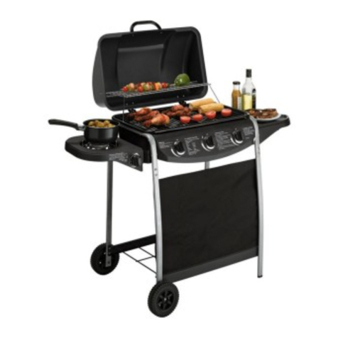
Argos KS0993 User manual

Model KS0993
Photographs are notto scale.
Specifications subjectto change
without prior notice. 0359
WARNING
• For outdoor use only. Notforcommercial use.
• Use only Propaneregulator37mbar.
• Read instructionsbeforeusingtheappliance.Failuretofollowinstructionscould
resultindeath,serious bodily injury, and/orproperty loss.
• Warning: accessibleparts may be very hot. Keep young childrenaway.
• Do not movetheapplianceduring use.
• Turn off the gas supply atthegasbottle afteruse.
• Any modification oftheappliance,misuse, orfailure tofollowthe instructions may
be dangerousandwillinvalidate yourwarranty.This does notaffect your statutory
rights.
• Retain theseinstructionsforfuturereference.
• Leak testyour barbecue annually. Check thehoseconnections are tightandleak
testthem each time you reconnectthe gas bottle.
FOR YOUR SAFETY
Ifyou smell gas:
1. Shut offgastotheappliance.
2. Extinguishany openflame.
3. Openbarbecuelid orhood.
4. Ifodourcontinues, discontinue use and
contact yourlocaldealer.
FOR YOUR SAFETY
1. Do notstoreorusepetrol or otherflammable
vapoursorliquidsinthe vicinity ofthisorany
otherappliance.
2. A gas bottlenot connected foruseshall not be
stored in thevicinity ofthis or any other
appliance.
Assembly and Operating Instructions for
2 Burner with Side Burner Gas BBQ
PDF created with pdfFactory trial version www.pdffactory.com

2
A. Parts List
Quantities varyaccording to model purchased. Specifications subject to change without priornotice. For more details on
hardware, please see the corresponding Hardware Reference Diagramforyour barbecue model.
CODE PART QTY
A1 Lid 1
A2 Lid handle 1
A3 Cooking grill 1
A4 Heat tent 1
A5 Hinge 2
A6 Burner 1
A7 Firebowl 1
A8 Grease cup hanger 1
A9 Grease cup 1
B1 Right front leg 1
B2 Right rearleg 1
B3 Leftfrontleg 1
B4 Left rear leg 1
B5 Wheel 2
B6 Left upper support 1
B7 Right upper support 1
B8 Control panelassembly 1
B9 Front canvas 1
B10 Bottom shelf 1
C1 Side table 1
C2 Side table front support 1
C3 Side table rear support 1
D1 Side burner assembly 1
D2 Side burner knob 1
D3 Side burner electrode 1
D4 Side burner 1
D5 Side burner grate 1
D6 Side burner front support 1
D7 Side burner rear support 1
E1 M6*20 bolt 8
E2 M6*12 bolt 20
E3 ST4*10 bolt 10
E4 M4 nut 2
E5 Washer 2
E6 M6 nut 8
E7 M5*8 bolt 8
E8 M6*15 Shoulder bolt 4
E9 M4*8 bolt 3
E10 Axle 2
E11 Heat tent support 1
E12 R-pin 2
E13 M5 nut 6
PDF created with pdfFactory trial version www.pdffactory.com

3
B1. Parts Diagram
Quantities varyaccording to model purchased. Specifications subject to change without priornotice. For more details on
hardware, please see the corresponding Hardware Reference Diagramforyour barbecue mode
B5
A5
D3
D5
D4
D2
D1
B7
B6
B9
B10
B5
B8
B2
B1
F4
B4
B3
B1
C3
C2
C1
D7
D6
A5
A9
A8
A7
A6
A4
A3
A2
A1
PDF created with pdfFactory trial version www.pdffactory.com

4
B2. Hardware ReferenceDiagram
Specifications subject to change without priornotice.
KS0993
E11 Heattent support 1PCS
E5 Washer2PCS
E4 M4NUT2PCS
E9 M4x8BOLT3PCS
E12 R Pin 2PCS
E10 Wheel-Axle 2PCS
E8M6x15Shoulder Bolt4PCS
E3ST4*10 6PCS
E1 M6x20 BOLT8PCS
E6 M6Nut8pcs
E2 M6x12BOLT20PCS
E13 M5NUT6PCS
E7 M5x8BOLT8PCS
E1 M6x20 Bolt 8PCS E2 M6x12 Bolt 20PCS
E3 ST4*10 Bolt 6PCS
E4 M4Nut2PCS E5 Washer2PCS E6 M6Nut8PCS
E10 Axle 2PCS
E9 M4x8 Bolt 3PCS
E13 M5Nut 6PCS
E7 M5x8 Bolt 8PCS
PDF created with pdfFactory trial version www.pdffactory.com

5
C. Assembly
TOOLS NEEDED FOR ASSEMBLY:
Medium size flat blade or Philips/cross-point screwdriver, adjustable spanner or metricspanner set
This barbecue requires two people for assembly.Please removeallpackaging materials from allindividualparts before
assembling.Please lay outallnuts and bolts and check lengths before assembling.Whilst everycareis takenduringthe
manufacture of this product, care must be taken during the assembly in case sharp edges are present.
1
Fig 1
Fix theleftfront leg(B3) and left rear leg (B4) on the bottom shelf (B10) using M6*12bolts (E2) asFig 1 .
2
Fig 2
Fix therightfront leg(B1) and left rear leg (B2) on the bottom shelf (B10) using M6*12bolts(E2) as Fig 2 .
F11
F3
F2
F6
F5
B4
B3
B10
B10
B1
B2
PDF created with pdfFactory trial version www.pdffactory.com

6
3
Fig 3
Install thewheels (B5) totheleftfront leg(B3) andleftrear leg(B4) usingthe axle(E10). Thenfixthe axle
(E10) by R pin (E12) as Fig3 .
4
Fig 4
Connect theleft upper support (B6) with theleft front leg (B3) andleftrear leg(B4) using M6*20bolts (E1)
and M6 nuts (E6) asFig 4.
Repeatthesameconnectionof therightupper support(B7) withtheright frontleg(B1) andrightrear leg (B2)
usingM6*20bolts (E1) and M6 nuts(E6) as Fig 4. Fix theboltstightly by thescrewdriver.
F10
F9
F8
F4
F1
B4
B3
B5
E10
E12
B6
B7
B3
B4 B1 B2
PDF created with pdfFactory trial version www.pdffactory.com

7
5
Fig 5
6
Fix thecontrol panel assembly (B8) on theleft upper support(B6)andrightupper support(B7) usingM6*12
bolts (E2) as Fig5.
Fig 6
Fix theheat tentsupport (E11) onthefirebowl (A7) usingM4*8 bolts (E9) and M4 nuts (E4) as Fig 6.
F7
B8
B6 B7
A7 E11
PDF created with pdfFactory trial version www.pdffactory.com

8
7
Fig 8a
Put the burner (A6) throughthehole of the firebowl (A7) asFig 8a.
Align all valves on the control panel assembly(B8) againsteach venturi of theburner (A6).Make sure all
thevalve tips go into the venturi tube completely with goodalignment. Fix theburner (A6) on thefirebowl
(A7) using ST4*10 bolts (E3) as Fig 8b.
Put theburner electrodein thevalveon the control panel assembly (B8).
Fig 7
Set thefirebowl (A7) on the leftupper support(B6) and right upper support (B7) using M6*20bolts (E1) as
Fig 7.
8
Fig 8b
B7
B6
A7
A6
A7
PDF created with pdfFactory trial version www.pdffactory.com

9
9
Fig 10
Putthewasher (E5) betweenthelidhandle(A2)andlid(A1).Aligntheholes andfixthelid handle(A1)onthe
lid (A1) using M5*8 bolts(E7) as Fig10.
Fig 9
10
Fix thehinge (A5) on the firebowl (A7) using M5*8bolts(E7) and M5 nuts (E13) asFig 9
A2
A1
A1
A2
E5
A5
PDF created with pdfFactory trial version www.pdffactory.com

10
11
Fig 12
Assemblethesidetable frontsupport (C2) andsidetable rear support (C3) to the sidetable (C1). Secure the
supportswith ST4*10screws (E3) as Fig12.
Fig 11
Fix thelid (A1) and firebowl (A7) bythehinge (A5)using M5*8 bolts(E7) and M5 nuts(E13) asFig 11.
12
E1
E3
E2
C1
C2
C3
PDF created with pdfFactory trial version www.pdffactory.com

11
13
Fig 14
Fix theside burner front support(D6) andside burner rear support (D7) to the sideburner assembly (D1)
usingM6*12bolt (E2) and lock thesupport narrowside by M6 nuts(E6) as Fig14.
Fig 13a
Install the side table assembly made on step 12 totherightupper support (B7) by M6*15 shoulder bolts (E8)
as Fig 13a and Fig13b.
14
B7 B7
Fig 13b
D1 D7
D6
D6
D1 D7
PDF created with pdfFactory trial version www.pdffactory.com

12
15
Fig 16a
Loosen the pre-assembledscrews onthe side burner valve ofthe control panel assembly(B8) as Fig 16a.
Fix theside burner valveon the sideburner panel bracketof theside burner assembly (D1) using the
screws asFig 16b.
Fig 15
Fix theside table assembly(D1) to the left upper support (B6) usingM6*12bolts (E2) asFig 15.
16
Fig 16b
PDF created with pdfFactory trial version www.pdffactory.com

13
Fig 16c
Fix the sideburner electrode(D3) on thesideburner assembly (D1) usingM4*8 bolt (E9). Putthesideburner
(D4) through thehole of side burner assembly (D1) as Fig 16c.
Adjusttheburner venturi againstthevalve.Make sure thevalvetip goes intotheventuri tubecompletely with
good alignment. Thentighten thesideburner (D4)on the side burner assembly (D1) usingM4*8 bolt(E9) as
Fig 16d.
Put the sideburner grate (D5) on the sideburner assembly (D1) andalign with 3holes as Fig 16e.
Connectthe side burner electrode (D3) to thevalve of the control panel assembly (B8) asFig 16f and 16g.
Fig 16d
D3
D4
D5
Fig 16e
Fig 16f Fig 16g
Electrode of Main Burner
Electrode of Side Burner
D4
D3
D5
PDF created with pdfFactory trial version www.pdffactory.com

14
18
Fig 18
Hangthegrease cup (A9)on the greasecup hanger (A8). Attach the FrontCanvas(B9) to the leftfrontleg
(B3) andright front leg (B1) as Fig 18. Secure the position with thevelcroon canvas edge.
F12
B7
A9
B9
Fig 17
Put thegrease cuphanger (A8) throughthehole onfirebowl (A7) asFig 17.
17
A8
PDF created with pdfFactory trial version www.pdffactory.com

16
D. Important Information
Please read these instructions carefully before
assembly anduse.
• Retain these instructions for future reference.
• For outdoors use only do not use indoors. Do
not use below ground level.
• For use with LPG bottled gas only.Aregulator of
37mbar must be used for propane.
• Do not use within 1mofany flammable structure
or surface.
• LP gas cylinders should notbeplaceddirectly
underneath the barbecue.
• LP gas cylinders must not bestored or used in the
horizontal position. Aleak would be very serious
and liquid could enter the gas line.
• When igniting barbecue open its hood before
lighting.
• Do not movethe barbecue while alight.
• This barbecue must not be leftunattended when
lit.
• The hood handle can become veryhot.Grip only
the centre ofthe handle. Use ofa cooking gloveis
advised.
• Use caution when opening the hood, as hot
steam inside is released upon opening.
• Parts of this barbecue become very hot care
must be taken when children,elderly people,and
animals are present.
• Always turn off the gas bottle when the barbecue
is not in use.
• Never cover abarbecue until ithas completely
cooled.
• Never use thebarbecue with theside shelfinthe
down position.
• Leak test annually, and whenever the gas bottle is
removed orreplaced.
• Do not store flammable materials near this
barbecue.
• Do not use aerosols near this barbecue.
• Failure to follow the manual’sinstructions could
result inserious injuryor damage.
• Ifyou have any queries regarding these
instructions, contact yourlocal dealer.
E.Gas andRegulator
This barbecue can useonly propane LPG bottled
gas. Propane bottles willsupply gas allyear round,
even on cold winter days. A spanner maybe required
to change gas bottles. The bottle should never be
stood on the trolley base and placeddirectlyunder
the barbecue. Gas bottles should never be stored or
used laid on theirside. Neverstore gas bottles
indoors.
YOU MUSTHAVE THE PROPER REGULATOR
AND BOTTLEINORDER FOR THEBARBECUETO
OPERATE SAFELY ANDEFFICIENTLY.USEOF
AN INCORRECTOR FAULTY REGULATOR IS
DANGEROUSAND WILL INVALIDATE ANY
WARRANTY. Please consult your localgas dealer
forthe most suitable gas bottles.
F.Installation
F1. Selecting aLocation
This barbecue is foroutdoor use only and should be
placed in awell-ventilated area. Take care to ensure
that itis not placed UNDERanycombustiblesurface.
The sides of the barbecue should NEVER be closer
than 1metre from any combustiblesurface.Keep
this barbecue away from any flammable materials!
F2. Precautions
Do not obstructanyventilationopenings inthe
barbecue body. Secure the gas bottle on the cylinder
holder and always tighten it with the black strap
provided. Should youneed tochange thegas bottle,
confirm that the barbecue is switched off,and that
there are no sources of ignition (cigarettes, open
flame,sparks, etc.)near beforeproceeding.Inspect
the gas hose to ensure it is free of any twisting or
tension. Thehose should hang freelywith nobends,
folds, or kinks that could obstruct free flow of gas.
Apart from theconnectionpoint,no partof the hose
should touch any hotbarbecue parts. Always inspect
the hose forcuts, cracks, or excessivewear before
use. If the hose is damaged, it must be replaced with
hose suitable foruse with LPGand meetthenational
standardsfor the country of use. The length of the
hose shallnot exceed 1.5m. N.B.-Thedate onU.K.
hose is the date of manufacture, notthe expirydate.
F3. Fixing the Regulator to the Gas Bottle
Confirmallbarbecue control knobs are in the off
position.Connect the regulator to the gas bottle
according toyour regulator and bottledealer’s
instructions.
F4. Leak Testing(Tobe performedinawell-
ventilated area.)
Confirm all control knobs are in the off position. Open
the gas controlvalveonthe bottle orregulator.
Check for leaks by brushing asolution of ½water
and ½soap overallgas systemjoints,including all
valveconnections, hose connections and regulator
connections. NEVER USE AN OPEN FLAME to test
forleaks at anytime.If bubbles form over anyof the
joints, thereis aleak.Turn off the gas supply and
retighten all joints. Repeat test. If bubbles form again,
do not use the barbecue. Please contact your local
dealer forassistance. Leak test your barbecue
annually.Check the hose connections are tightand
leak test themeach timeyou reconnect the gas
bottles.
PDF created with pdfFactory trial version www.pdffactory.com

17
G.Operation
G1. Warning
• Beforeproceeding,makecertainthatyou
understand the IMPORTANT INFORMATION
section ofthis manual.
G2. Preparation Before Cooking
To preventfoods from stickingtothecooking grill,
please use along handled brush to apply alight coat
of cooking or vegetable oil before each barbecuing
session. (Note: When cooking forthefirst time,
paintcolours may change slightlyas aresult.
This is normal and shouldbe expected.)
G3. Lightingthe MainBurner
• Open the barbecue hood.
• Ensure all knobs are in the off position. Open the
gas control valveon the gas bottle orregulator.
• Push in and turn the burnercontrolknobtothe
Maxposition.Press the ignition button rapidly
severaltimes untilleftportion of the burner is lit.
If burner fails to ignite, turn control knob to the off
position and turn gas off at the bottle orregulator.
Waitfive minutes, then repeat the abovesteps.
After successful lighting of the leftside, ignite the
remainingportion of the burner.If the burner fails
to ignite after following above procedure, turn all
the knobs totheoff position.Close the gas valve
on the gas bottle. Wait5 minutes, then repeatthe
above steps. Ifthe barbecue stillfails to light,
please refer to the manual ignition instruction in
the section below.
• After ignition, the burner should be burned at the
high position for 3-5 minutes in order to preheat
the barbecue.This process should be done
before every cooking session. The hood (where
applicable) should be open during preheating.
• After completion of preheating, the burner should
normallybe turned down to alower position for
best cooking results.
G4. Manual IgnitionInstructionfor MainBurner
• Insert lit match through the match-lighting hole at
the bottom ofthe barbecue body.
• Push in and turn the rightmost controlknob anti-
clockwise to the max position.
• After the right portion of the burner is lit,lightthe
remaining portionofthe burner.
• If burner fails toignite,contactyour local dealer
forassistance.
• After ignition, the burner should be burned at the
maxposition for 3-5 minutes in order to preheat
the barbecue.This process should be done
before every cooking session. The hood (where
applicable) should be open during preheating.
• After completion of preheating, the burner should
normallybe turned down to alower position for
best cooking results.
G5. Lightingthe Side Burner
• Keep side burner free.
• Set the control knob to off and turn on the gas
supply.
• Push in and turn thecontrolknob anti-clockwise
to max position.
• Push the ignitionbuttonseveraltimes andthe
burner should ignite.
• Ifthe burner fails to ignite after above procedure,
turn the knob to the off position and close the gas
valve.Wait5minutes and then repeat the above
steps. If the barbecue stillfails to light, please
referto the manualignition instruction inthe
section below.
G6. Manual IgnitionInstructionfor SideBurner
• Set the controlknob tothe off position.
• Apply a lit match on the gap to burner ports.
• Push and turn thecontrol knob anti-clockwise to
max position and the burner should ignite. If the
burner fails to ignite, contact your local dealer for
assistance.
G7. Roasting Hood Cooking
Barbecues equipped with aroasting hood give the
option ofcooking with hood closed to form an ‘oven’
forroasting food, such as joints of meat,whole
chickens, etc.
Whenroasting,turntheburner under the foodtothe
OFFposition.Close the hood and turn theother
burner down to alower setting i.e.low to mediumto
achievethetemperaturerequired.DONOT ALLOW
YOUR BARBECUETOOVERHEAT. Avoid lifting the
hood unnecessarily as heat is lost each timethe
hood is opened.
G8. Endof Cooking Session
Aftereach cooking session, turnthe barbecue burner
to the “max”positionand burn for 5minutes. This
procedure willburn off cooking residue, thus making
cleaning easier.Make sure the hood is open during
this process.
G9. TurningOff Your Barbecue
When you havefinished using your barbecue, turn all
the controlvalves fully clockwise to the “Off”position,
then switch off thegas at the bottle.Waituntil the
barbecue is sufficiently cool before closing its hood.
H. CARE AND MAINTENANCE
Regularlyclean your barbecue between uses and
especially after extended periods ofstorage. Ensure
the barbecue and its components are sufficiently cool
beforecleaning. Donotleave the barbecue exposed
to outside weather conditions or stored indamp,
moist areas.
• Never douse the barbecue with water when its
surfaces are hot.
• Never handlehot parts with unprotected hands.
PDF created with pdfFactory trial version www.pdffactory.com

18
H1. CookingGrill
Clean with hot soapy water. To removeany food
residue, use amild creamcleaner on anon-abrasive
pad. Rinse well and dry thoroughly.
H2. Burner Maintenance
Your burner has been preset foroptimalflame
performance. You willnormallysee a blue flame,
possibly with asmallyellow tip when the burner is
alight.If the flamepattern is significantlyyellow, this
could be a problem caused by grease from cooking
blockingthe burner or spiders or other insects in the
burner venturi.This can result in the flow ofthe gas
and air mixture being restricted orblocked which may
result ina fire behind the controlpanel causing
serious damage to your barbecue.If thishappens,
the gasshouldbe immediately turnedoff at the
bottle. Burners should be inspected and cleaned on
a regular basis in addition to the following conditions:
1) Bringingthe barbecue out of storage.
2) One or moreofthe burners do not ignite.
3) The burner flame pattern is significantly yellow.
4) The gas ignites behind the control panel.
To clean a burner, remove it from the barbecue. The
outside ofthe burner canbe cleaned with a wire
brush. Clean the portholes with a pipe cleaner or
piece of wire. Take care notto enlarge the portholes.
Clean the insect screen on the end ofthe venturi
tube with a bristle brush (i.e. anold toothbrush).
Clean the venturitube with a pipe cleaner or piece of
wire. You may need a torch to see into the venturi
tube to makesure itis clear. ”Turn the burner up on
end and lightlytap against apiece of wood to
dislodge any debris from inside.”
H3. Barbecue Body
Regularly removeexcess grease or fat from the
barbecue body with asoft plasticor wooden scraper.
Itis notnecessary to remove all thegrease from the
body. If you need to clean fully, use hot soapy water
and acloth, or nylon-bristled brush only. Remove
cooking surfaces and burners before fullcleaning. Do
not immerse the gas controls or manifold in water.
Check burner operation after carefully refitting into
body.
H4. Fixings
Allscrews and bolts, etc.should be checked and
tightened on a regular basis.
H5. Storage
Store your barbecue in a cool dryplace. Itmust be
inspected on a regular basis as damp or
condensation can form which mayresult in damage
to the barbecue. It may be necessary to dry the
barbecue and the inside ofthe cover if used. Mould
can grow under these conditions and should be
cleaned and treated if required.Any rust that is found
that does not come into contact with the food should
be treated with a rust inhibitor and paintedwith
barbecue paint or a heatresistant paint. Chrome
plated warming racks and grills should be coated
with cooking oil.Wrap the burners in aluminiumfoil to
help preventinsects or other debris from obstructing
the burners.
The gas bottlemust bealways be disconnected from
the barbecue and stored in awell ventilated area at
least 1 metreaway from any fixedignitionsource. Do
not store inside residential accommodation. Never
store cylinders below ground level(e.g.cellars). Do
not let children tamper withbottles.
I. Technical Specifications
This barbecue grill ismanufacturedby:
Donguang KingsunEnterprises Co.Ltd.
Address: Xicheng Area 2, ShiyongVillage, Hengli
Town, DongguanCity,GuangdongProvince,
China
Model Number KS0993
Gas Category I3P (37)
Type ofGas Propane
Gas Pressure 37 mbar
Pin Number 359/BU/1016
InjectorSize (Main Burner) 0.75mm
InjectorSize (Side Burner) 0.74mm
TotalHeat Input 7.0 kW
2 Burner Heat Input4.7 kW
Side Burner HeatInput2.3 kW
Gas Consumption 500 g/h
Country of Destination GB and IE
PDF created with pdfFactory trial version www.pdffactory.com

19
L. Troubleshooting
Problem PossibleCause Solution
Burnerwill notlightusing the
ignitionsystem LP gas cylinder isempty Replace with fullcylinder
Faultyregulator Have regulatorchecked orreplace
Obstructionsin burner Clean burner
Obstructionsingasjetsor gas hose Clean jets andgashose
Electrode wire isloose ordisconnected on
electrode orignition unit. Reconnect wire
Electrode orwire isdamaged Change electrode and wire
Faultypushbuttonignitor Change ignitor
Burnerwill notlight with amatch LP gas cylinder isempty Replace withfullcylinder
Faultyregulator Have regulatorchecked orreplace
Obstructionsin burner Clean burner
Obstructionsingasjetsor gas hose Clean jets andgashose
Low flame orflashback(fire in
burnertube a hissingor
roaringnoise may be heard)
LP gas cylinder toosmall Use largercylinder.
Obstructionsin burner Clean burner
Obstructionsingasjetsor gas hose Clean jets andgashose
Windyconditions. Use BBQin a more sheltered position
Gasvalveknobdifficultto turn Gasvalve jammed Replace gasvalve
Argos Limited, MK9 2W
PDF created with pdfFactory trial version www.pdffactory.com
Table of contents
Other Argos Grill manuals

Argos
Argos 345/1319 User manual

Argos
Argos 307223 User manual

Argos
Argos 954/4031 User manual

Argos
Argos KS10013 User manual

Argos
Argos 953/8559 User manual

Argos
Argos Sainsbury's 951/4236 User manual

Argos
Argos 345/1247 User manual

Argos
Argos 2901365 User manual

Argos
Argos 609/7550 User manual

Argos
Argos 345/0925 User manual
Popular Grill manuals by other brands

GRANDSTATE
GRANDSTATE HAWK 411 SAFETY, INSTALLATION, OPERATION AND MAINTENANCE INSTRUCTIONS

Nexgrill
Nexgrill 720-0888N Assembly instructions

GBG
GBG GBGHSGRLR manual

Happy Garden
Happy Garden SEVILLE BQ551 quick start guide

George Foreman
George Foreman 25040-56 manual

Char-Broil
Char-Broil 465640212 Product guide