Argus PiCUS TreeQinetic User manual

PiCUS TreeQinetic
Manual
This manual is valid for PiCUS TreeQinetic systems of these versions:
Hardware Version: 0.1.0000
Firmware Version: 0.0.0707
App Version: 1.0
Manual version: 28 Mai 2021
argus electronic gmbh
Erich-Schlesinger-Straße 49d
18059 Rostock
Germany
Tel.: +49 (0) 381 - 496814 –40
www.argus-electronic.de
email: kontakt@argus-electronic.de

PiCUS TreeQinetic Manual
2
1 Content
2Abreviations and Acknowledgements............................................................................. 4
3.1 Intended Use........................................................................................................... 4
3.2 Designated Application............................................................................................ 5
3.3 Disclaimer ............................................................................................................... 5
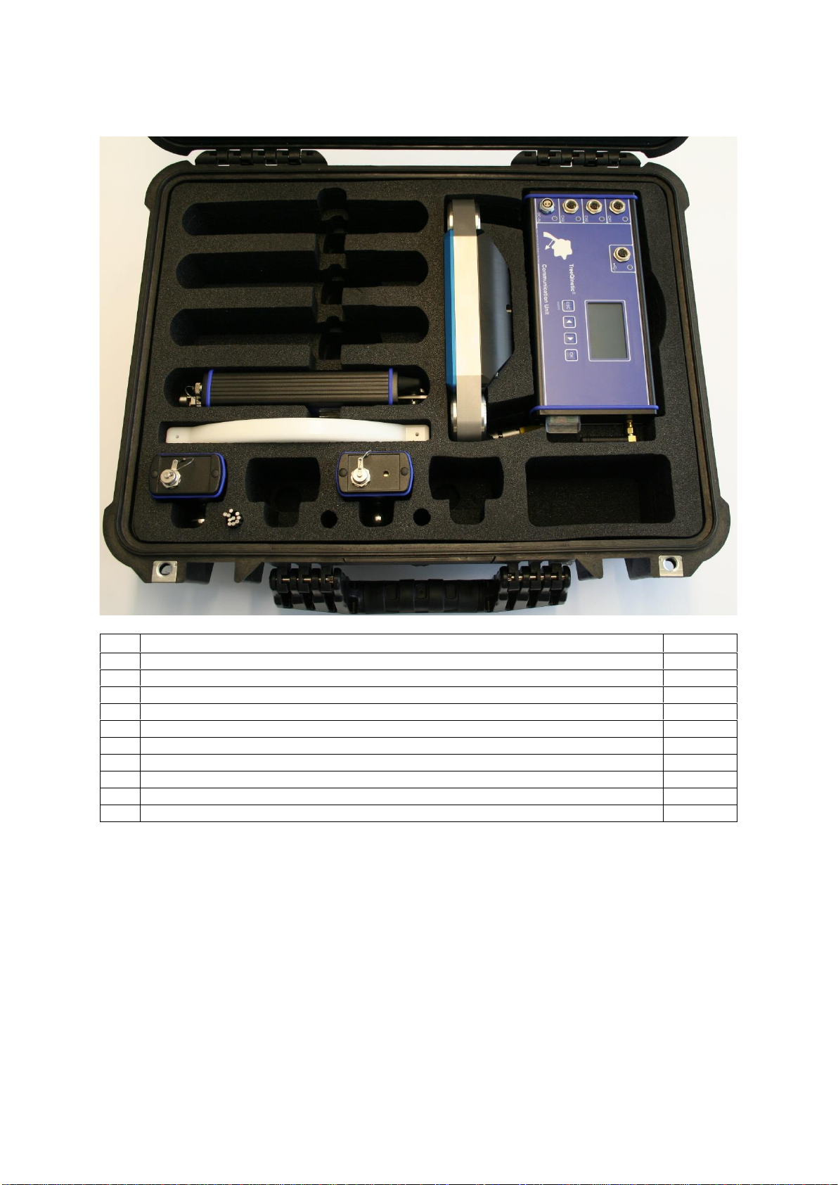
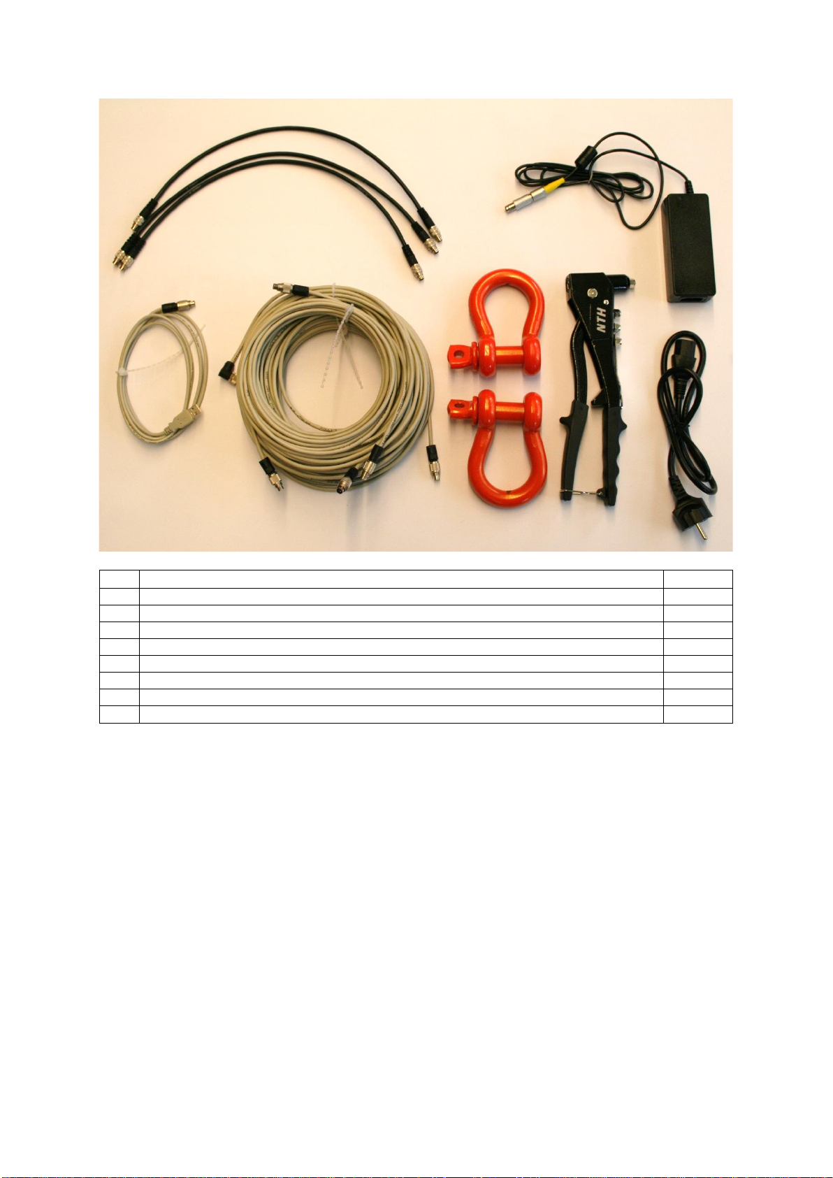
3.4 Packing List (Starter)............................................................................................... 6
4Measuring Instruments................................................................................................... 8
4.1 Description of System Components ........................................................................ 8
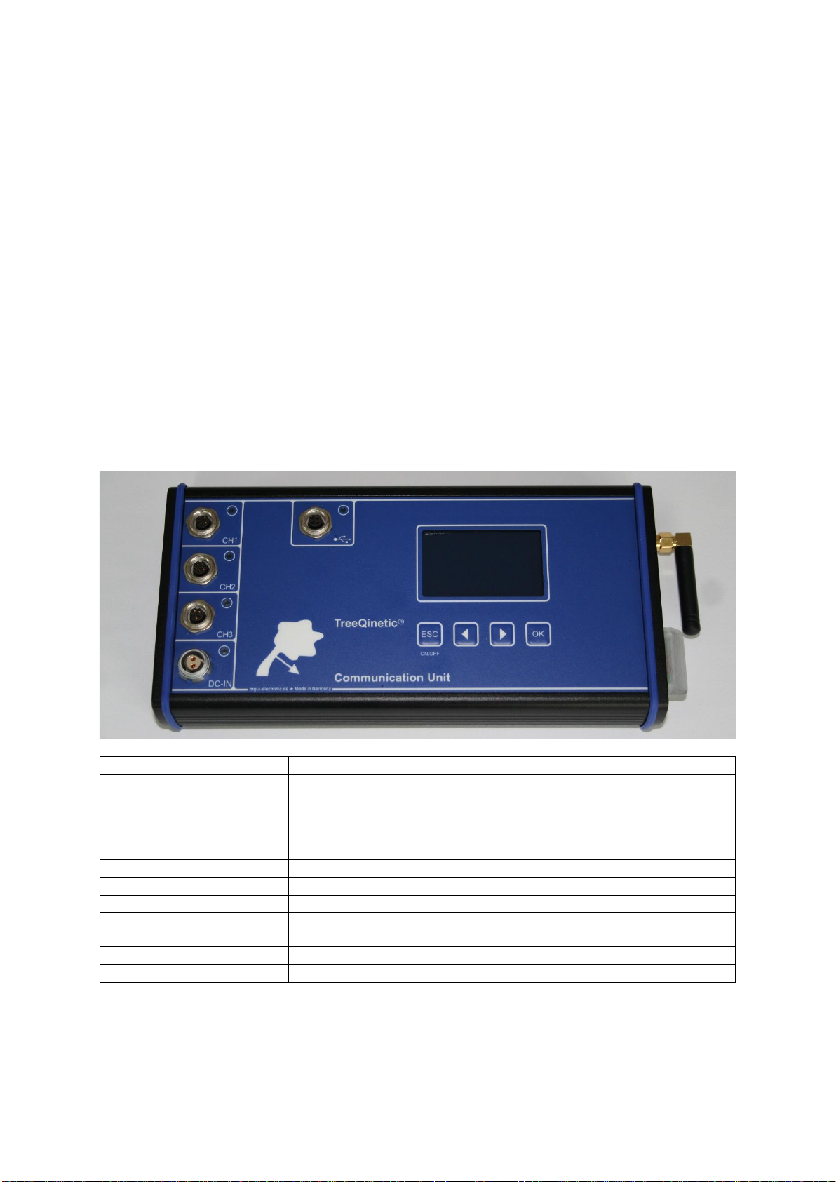
4.1.1 Communication Unit......................................................................................... 8
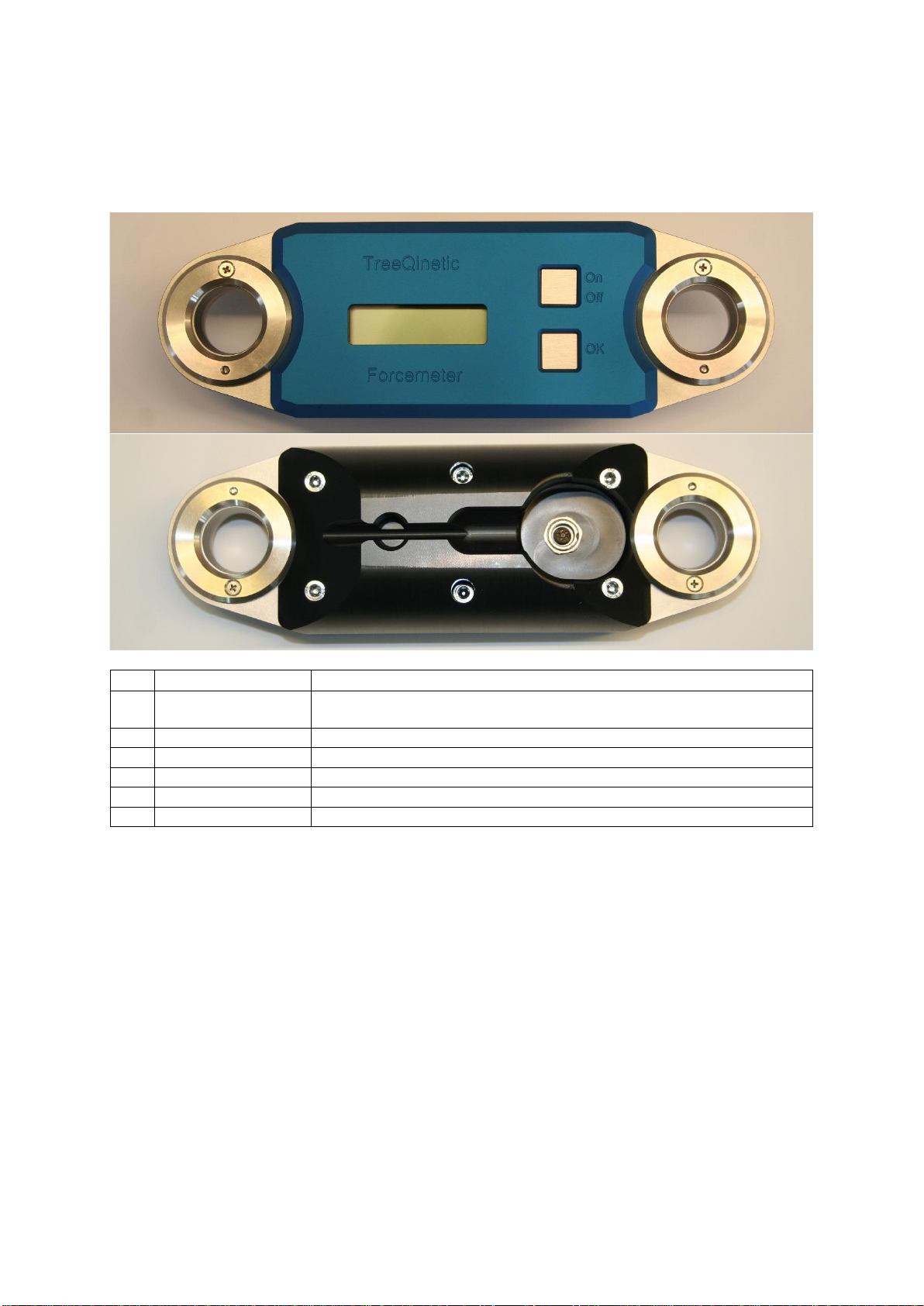
4.1.2 Forcemeter......................................................................................................10
4.1.3 Inclinometer ....................................................................................................11
4.1.4 Elastometer.....................................................................................................14
4.1.5 Overlaod Indicator...........................................................................................16
4.1.6 Cables.............................................................................................................17
4.1.7 Case ...............................................................................................................17
4.1.8 Eightfold Charger (Optional)............................................................................18
4.1.9 Anemometer (Optional)...................................................................................19
4.2 General Operating Instructions...............................................................................20
4.2.1 Ambient Conditions.........................................................................................20
4.2.2 Module Addresses ..........................................................................................20
4.2.3 Automatic switch-off........................................................................................21
4.2.4 Charging .........................................................................................................21
4.2.5 Maintenance ...................................................................................................22
4.2.6 Spread of Infestations .....................................................................................22
4.3 Calibration..............................................................................................................22
5App................................................................................................................................23
5.1 Installation..............................................................................................................23
5.2 Starting the App .....................................................................................................23
5.2.1 Permissions ....................................................................................................23
5.2.2 Features of Android.........................................................................................24
5.2.3 Features of iOS...............................................................................................24
5.3 Control Concept.....................................................................................................24
5.3.1 General...........................................................................................................24
5.3.2 Features of Android.........................................................................................25
5.3.3 Features of iOS...............................................................................................25
5.4 Tab –Control .........................................................................................................26
5.4.1 Page –Communication Unit............................................................................26
5.4.2 Page –Info......................................................................................................27
5.5 Tab –Project..........................................................................................................27
5.5.1 Page –Management.......................................................................................27

PiCUS TreeQinetic Manual
3
5.5.2 Page –Tree Data............................................................................................27
5.5.3 Page –Test Setup ..........................................................................................28
5.5.4 Page –Forcemeter .........................................................................................29
5.5.5 Page –Elastometer.........................................................................................30
5.5.6 Page –Inclinometer ........................................................................................30
5.6 Tab –Measure.......................................................................................................31
5.6.1 Page –Control................................................................................................31
5.6.2 Page –Live View Numeric ..............................................................................32
5.6.3 Page –Live View Diagram..............................................................................33
5.7 Tab –Data View.....................................................................................................33
5.7.1 Page –Result..................................................................................................33
5.7.2 Page –Forcemeter .........................................................................................34
5.7.3 Page –Elastometer.........................................................................................34
5.7.4 Page –Inclinometer ........................................................................................35
5.7.5 Page –Anemometer .......................................................................................35
5.8 Additional Information / Background Processes .....................................................35
5.8.1 Interruption of the Bluetooth Connection .........................................................35
5.8.2 Vibrating Alert..................................................................................................35
5.8.3 Internal Calculations........................................................................................36
5.9 Managing the Measurement Data ..........................................................................37
5.9.1 Project Structure .............................................................................................37
5.9.2 Data Transmission..........................................................................................37
5.9.3 Compatibility with Arbostat..............................................................................38
6Software........................................................................................................................39
7Technical Information....................................................................................................40
7.1 PTQ Com Unit........................................................................................................40
7.2 PTQ Forcemeter ....................................................................................................40
7.3 PTQ Inclinometer ...................................................................................................41
7.4 PTQ Elastometer....................................................................................................41
7.5 PTQ Überlast-Warner.............................................................................................42
7.6 PTQ Case..............................................................................................................42
7.7 Requirements Mobile Device..................................................................................42
7.8Requirements PC...................................................................................................42

PiCUS TreeQinetic Manual
4
2 Abreviations and Acknowledgements
PTQ PiCUS TreeQinetic = Name of the whole system
PTQ.App Measuring software to be used under Android or iOS
PTQ Com Unit Communication Unit
Module Part of the PTQ system like Elastometer, Inclinometer,
Forcemeter od Anemometer
Text fields displayed in an app on the mobile phone, in software on the PC or labels on the
outside of a device are shown in this manual in gray color and bold italic letters EXAMPLE.
Data input fields in an app on the mobile phone or in software on the PC are shown in this
manual in green and bold italics EXAMPLE.
Data display elements in an app on the mobile phone or in software on the PC are shown in
this manual in blue color and bold, italicized text EXAMPLE.
Cross-references to other chapters of this manual or references to external sources are written
in italics and underlined.
Potential sources of error are indicated with CAUTION!, notes with the keyword NOTE,
followed by a short explanation in italics.
3 General Information
This chapter deals with general information.
3.1 Intended Use
PiCUS tree measurement technology offers tree experts a comprehensive set of diagnostic
tools for the detection and evaluation of defects in trees.
The tree static pulling test is so far the only method that allows conclusions to be drawn on
uprooting and breaking safety in equal measure.
The PiCUS TreeQineticmeasuring instruments are optimized for such pulling tests andprovide
the necessary data basis for safety calculations.
When using the system, the ambient conditions specified in the General Operating Instructions
and Technical Information must be observed. Otherwise a faultless function of the system
cannot be guaranteed.
The PiCUS product family stands for measuring instruments that not only provide precise
results but are also designed to reliably accompany the user in the field for a long time. They
are designed to be correspondingly robust. Nevertheless, they are highly sensitive, electronic
measuring instruments. Careful handling that takes this into account reduces failures and
maintenance requirements and significantly increases service life and reliability.

PiCUS TreeQinetic Manual
5
3.2 Designated Application
The PiCUS TreeQinetic System is intended for use as measuring instrument in tree static
pulling tests. In the pulling test, the tree under investigation is subjected to a measured load in
a controlled manner using a pulling rope, while the reaction of the trunk and roots to this load
is recorded. The reaction of the tree to the known load is set in relation to the expected wind
load in a storm, thisratioexpresses the uprootingand breaking safety. TheTreeQinetic system
provides the user with the data basis needed to perform tree statics calculations.
The forcemeter is used to measure the force introduced into the tree and should be installed
between the tree and the entire pulling apparatus. It is designed for loads up to 60 kN (about
6 tons). The Forcemeter may only be attached with the shackles supplied or approved by the
manufacturer.
The elastometer measures the change in the distance between the two measuring points. For
this purpose they are attached to the needles supplied, which are hammered into the tree with
the gauge. Elastometers are designed for measuring elastic elongation or compression in the
range of up to several hundred µm.
Inclinometers measure the inclination of the tree part to which they are attached. First, the
inclinometer mount is attached, onto which the measuring instrument is then placed and
aligned.
The com unit allows to receive and record the measurement data at a safe distance from the
tree in case of unforeseen failure.
All PiCUS TreeQinetic sensor components are designed to measure fine movements and
should never be subjected to shocks or falls. Do not mount measuring instruments on the
respective holders until they are completely tight. After installing the rope, attach themeasuring
devices and disassemble the measuring equipment first to avoid contamination and damage
during other work.
3.3 Disclaimer
Using the PTQ on other objects than trees may damage the PTQ, its components or the object.
The measurement results of the PTMSO require interpretation by qualified experts.
Conclusions about the condition of the tree, derived from the measurement data and analyses
generated by the PTQ, are the sole responsibility of the person drawing the conclusion. Neither
the manufacturer of the devices nor the seller can be held liable for consequences arising from
the application of the PTQ.
Damage to the devices caused by improper handling is not covered by the warranty. It is
strongly recommended to handle all PTQ components with due care to keep them in good
working order for a long time.
All technical specifications are subject to change without notice.

PiCUS TreeQinetic Manual
6
3.4 Packing List (Starter)
No.
Designation
Amount
1
Case
1
2
Communication Unit
1
3
Forcemeter
1
4
Inclinometer
1
5
Inclinometer mount (in the lid compartment, not pictured)
1
6
Elastometer
1
7
Elastometer needles (in pairs)
5
8
Gauge for Elasto needles
1
9
Overload Indicator
1
10
Measuring Software and digital manual (USB drive)
1
Table 1 –Packing list PTQ Starter Part I
1
2
3
4
6
7
8
2
9

PiCUS TreeQinetic Manual
7
No.
Designation
Amount
11
PTQ Charging cable
3
12
PTQ USB cable
1
13
Data cablel 5 m
2
14
Data cable 30 m (Forcemeter)
1
15
Shackle (Forcemeter)
2
16
Pliers for Elasto needles (hand riveter)
1
17
Power supply
1
18
Power supply cable
1
Table 2 –Packing List PTQ Starter Part II
11
12
13; 14
15
16
17
18

PiCUS TreeQinetic Manual
8
4 Measuring Instruments
4.1 Description of System Components
This chapter gives an overview of the components, structure and functions of PiCUS
TreeQinetic.
4.1.1 Communication Unit
The PTQ communication unit (abr. com unit) is the central part of the system. It sends
command signals to the sensor moduls, receives measuring data from them and forwards the
data to the PC or mobile device. Apart from that the com unit works as charger for the PTQ
starter kit.
NOTE
There are various generations of com units. Only the version which was manufactured from
mid 2020 on (serial number ending with -BT5) is able to connect to mobile devices such as
tablets and smartphones.
To ensure communication to older laptop computers a BT5 USB dongle is delivered with these
devices.
No.
Designation
Function
1
Charging Port / Data
Input
•During charging one sensor module can be connected to this port
using a charging cable (45 cm).
•If during a measurement a cable connection is necessary one
sensor module may be connected using the data cable.
2
Charge Input (DC-IN)
•Input for power supply
3
USB Port
•Port for USB cable
4
On / Off
•Turns com unit on or off
5
Arrow Buttons
-
6
OK
-
7
Display
•Displays status of connected sensor modules
8
Radio antenna
•Connection to modules
9
Bluetooth antenna
•Wireless connection to computer
Table 3 –PTQ Communication Unit: Operation and Display Elements
1
1
1
2
3
4
5
6
7
8
9

PiCUS TreeQinetic Manual
9
Operation
The com unit is switched on or off by briefly holding the on/off switch. After starting, the display
shows device information and the serial number. After a device search has been carried out,
the display lists the connected modules in order of device type.
The individual measuring devices (elastometer, inclinometer, forcemeter, anemometer) are
connected to the com unit via a radio link or a cable connection. Several modules with mixed
connections can be used simultaneously.
Connection via radio link
1. Turn off modules
2. Unplug cable
3. Turn on modules
All modules which are turned on without a cable connected to them automatically activate
the radio link.
Cable connection
1. Turn off modules
2. Plug a data cable to the module on one side and the com unit on the other side
3. Turn on modules
The TreeQinetic system can be connected to a PC via the com unit using Bluetooth or USB.
Using USB:
1. Turn off com unit
2. Connect USB cable to USB socket of the active PC
3. Turn on com unit
4. Start measuring software after establishing the cable connection
Using Bluetooth:
1. Turn off com unit
2. Unplug USB cable
3. Turn on com unit
If the com unit is turned on without a USB cable connected to it, it automatically activates
the Bluetooth mode.

PiCUS TreeQinetic Manual
10
4.1.2 Forcemeter
The Forcemeter is mounted on the rope to measure the force exerted on the tree.
Explanation of Parts
No.
Designation
Function
1
Attachment eyes
•Attachment points for shackles. Use with delivered iron shackles
only!
2
Display
•Displays menu
3
On / Off
•Turn on / off
4
OK Button
•Navigation in the menu
5
Cable Socket
•Connector for charge or data cable
6
Cable Screw
•Strain relief screw for data cable
Table 4 –Forcemeter: Operation and Display Elements
Operation
The forcemeter is switched on or off by briefly holding the on/off switch. The display shows the
current measuredvaluesfor force and rope angle as well as the battery voltage and the module
address.
By pressing the OK button once, the forcemeter switches to offset mode ("zeroing"). By
pressing the OK button again, the five-second calibration cycle of the offset value is initiated.
In most applications, it is recommended to have the offset value determined by a command
from the com unit for all modules simultaneously. Ideally, this is done immediately before the
actual measurement, theapp doessoautomatically. To set theoffset no load should beapplied
to the Forcemeter.
If the OK button is held down for 3 seconds, the forcemeter switches to the address menu.
Here the module address can be set by pressing the OK button. To save the set address,
press and hold the OK button for three seconds.
1
1
6
5
4
3
2

PiCUS TreeQinetic Manual
11
Mounting
To attach the forcemeter one of the steel shackles supplied is attached to each side. The bolt
is inserted into the hole of the forcemeter housing. The screwed-on spacer rings centre the
forcemeter, they are not designed for taking up loads.
The shackles are used to connect the pull rope on one side and the tree on the other side to
the measuring device.
CAUTION!
The Forcemeter is designed exclusively for use with the steel shackles supplied!
All other attachment devices such as carabiners, ropes, eyes, hooks, so-called soft shackles,
and similar can cause incorrect measurement results and damage the forcemeter (especially
the attachment of the round spacers)!
Figure 1- Forcemeter with properly attached shackles.
4.1.3 Inclinometer
PTQ inclinometers measure the inclination of the part of the tree to which they are attached,
usually the base of the trunk. With the measured data of an inclinometer, calculations of
stability (uprooting safety) can be made.
CAUTION!
Inclinometers show a temperature drift! This means that the displayed value changes with the
temperature of the sensor.
It is recommended to let the inclinometers adjust to the local temperature before measuring.
The "zeroing" should be carried out immediately before each pull. Protecting the inclinometers
from direct sunlight during measurement can help to eliminate drift effects.

PiCUS TreeQinetic Manual
12
Explanation of Parts
No.
Designation
Function
1
Display
•Displays menu
2
Direction Indicator
•Indicates inclination direction
3
On / Off
•Turn on / off
4
OK Button
•Navigation in the menu
5
Status LED
•Flashing during measurement
6
Ball Magnet
•Attachment and alignment on inclino mount
7
Cable Socket
•Connector for charge or data cable
8
Antenna
•Radio connection
Table 5 –Inclinometer: Operation and Display Elements
Operation
The inclinometer is switched on or off by briefly holding the on/off switch. The display shows
the current measured value, the battery voltage and the module address. After switching on,
the firmware version, module address and the individual serial number of the respective
measuring instrument are temporarily displayed.
By pressing the OK button once, the Inclinometer changes to the offset mode ("zeroing"). By
pressing the OK button again, the five second calibration cycle of the offset value is initiated.
In most applications, it is recommended to have the offset value determined by a command
from the com unit for all modules simultaneously. Ideally, this is done immediately before the
actual measurement, the app does so automatically.
If the OK button is held down for 3 seconds, the Inclinometer switches to the address menu.
Here the module address can be set by pressing the OK button. To save the set address,
press and hold the OK button for three seconds.

PiCUS TreeQinetic Manual
13
Mounting
Inclinometers are connected to the magnet of an inclinometer mount using the ball on the back.
The infinitely adjustable guide of the ball allows the inclinometer to be precisely aligned before
measurement. That means the front side with the display is flat horizontal while X and Y value
display zero with minor decimals.
The attachment of the mount must be completed before the sensitive measuring device is
connected to it. Before dismantling the mount, the inclinometer is removed. The measuring
device must not be subjected to mechanical loads such as those that occur when attaching or
removing the holder!
There are two different versions of
these inclinometer mounts. The newer
design is pressed against the bark at
the desired position and fastened with
a pan head screw. By tightening the
screw, the three tips are pulled against
the surface and prevent slipping and
twisting. The screw used should be
adapted to the tree species and the
application.
The older type is hammered into the tree with two pointed thorns. It must be ensured that the
holder and thus also the measuring instrument is firmly connected. The thorns are pulled out
again by lightly levering under the base plate. Too strong tilting should be avoided, otherwise
the thorns will bend.
CAUTION!
Permanent magnets are damaged by mechanical stress! Magnets must never be hit directly
with a hammer, instead use the protective plastic cover supplied.
Figure 3 –Left: Mount of old type inclino mount. Right: unmounting of old inclino mount by gentle
levering. It is recommended to lever on both sides alternately.
Figure 2 –New Inclino mount, fastened with a single pan
head screw

PiCUS TreeQinetic Manual
14
4.1.4 Elastometer
The PTQ Elastometer measures the change in the length of the wood fibres to which it is
connected. This change in length can be positive (elongation or strain) or negative
(compression).
Explanation of Parts
No.
Designation
Function
1
Display
•Displays menu
2
Locking Knob
•Physical lock secures mechanics during transport
3
On / Off
•Turn on / off
4
OK Button
•Navigation in the menu
5
Status LED
•Flashes during measurement
6
Upper Bracket
•Fastening oft he upper needle
7
Lower Bracket
•Fastening oft he lower needle
8
Cable Socket
•Connector for charge or data cable
9
Antenna
•Radio connection
Table 6 –Elastometer: Operation and Display Elements
Operation
The Elastometer is switched on or off by briefly holding the on/off switch. The display shows
the current measure value, the battery voltage and the module address. After switching on, the
firmware version, module address andthe individual serialnumber of the respective measuring
instrument are temporarily displayed.
By pressing the OK button once, the Elastometer changes to the offset mode ("zeriong"). By
pressing the OK button again, the five second calibration cycle of the offset value is initiated.
In most applications, it is recommended to have the offset value determined by a command
from the com unit for all modules simultaneously. Ideally, this is done immediately before the
actual measurement, the app does so automatically.
If the OK button is held down for 3 seconds, the Elastometer switches to the address menu.
Here the module address can be set by pressing the OK button. To save the set address,
press and hold the OK button for three seconds.
Elastometers are equipped with a mechanical lock of the actual measuring apparatus. If this
button sticks out on the back (side away from the display), the mechanics is locked. If the
button protrudes from the display, the mechanics are free and ready to measure.

PiCUS TreeQinetic Manual
15
Montage
To attach an elastometer to the tree, you need a pair of elastometer needles, the needle gauge
and a hammer.
The needles are inserted into the gauge so that the tips point away from the handle and
towards the tree. The gauge is placed where the elastometer is to be attached. Then the
needles are driven in at the distance given by the gauge. The needles must be firmly attached
to the actual wood (xylem) to ensure that the fibre length change is transmitted to the gauge.
The gauge is carefully pulled off.
CAUTION!
The needles must not bedriven in anyfurther as long as the sensitive elastometer is connected
to them!
The locked elastometer is placed onthe lower needle withthe lower needle bracket andinitially
held slightly tilted to the right. The bottom of the display points to the tree. A slight tilting
movement brings the upper needle bracket up to the upper needle. If the distance betweenthe
needles is correct, the bracket will hit exactly. The elastometer is positioned so that it comes
as close as possible to the tree without the instrument touching the tree.
The lower and upper knurled screws are tightened by hand and fix the gauge in place. After
tightening, the lock can be released. This should be possible without strong resistance or
tension.
The first measured value of the elastometer (before zeroing) should be in the range of a few
hundred µm at most. If the value is above 1000 µm, the device has not been attached with
sufficient precision.
To pull out the needles without damaging them the rivet pliers should be used (3.1 mm).
Figure 4 –Attaching the elastometer

PiCUS TreeQinetic Manual
16
4.1.5 Overlaod Indicator
The PTQ overload indicator clearly warns by means of optical and acoustic signals when the
measured values reach and exceed the given limits.
Explanation of Parts
No.
Designation
Function
1
Flashing lights
•Optical warning
2
Status LED
•Status indicator
3
On / Off
•Turn on / off
4
Ball Magnet
•Attachment / Alignment
5
Loudspeaker
•Acoustic warning
6
Cable socket
•Anschluss Ladekabel oder
Datenkabel
7
Antenna
•Radio connection
Table 7 –Overload Indicator: Operation and Display Elements
Operation
CAUTION!
Do not look directly into the flashing lights when turning on the
device!
The overlaod indicator is switchen on or off by briefly holding the
on/off switch.
The flashing lights also indicate the measurements state.
Blue flashing indicates the stand-by-mode, the device is not
receiving data.
Green light means the overload indicator is connected but no
value is exceeding its respective limit.
Red flashing accompanied by the sounding of the alarm tone
indicates that one more more values have reached or exceeded the given limits.
The limits are managed in the computer software or the app on the mobile device.
NOTE
Older systems do not display the overload indicator in the listing of connected devices. When
the overload indicator shows green light in the beginning of the measurement it is connected
correctly.
A red status LED indicates that the battery needs to be charged.
Mounting
Overload warning devices are attached to the tree using inclinometer mounts. They should be
positioned with good visual contact to the winch operator.
1
2
3
5
6
7

PiCUS TreeQinetic Manual
17
4.1.6 Cables
Explanation of Parts
No.
Designation
Function
1
Power supply cable
•Connecting the power supply to the grid
2
Power supply
•Power supply of the com unit or eightfold charger
3
Charging cable
•Connecting the modules to power supply or eightfold charger
4
Data cable (5 m)
•Transmitting data from elastometer or inclinometer to com unit. Do
not use for charging!
5
Data cable (30 m)
•Transmitting data from forcemeter to com unit. Do not use for
charging!
6
USB cable
•Backup for transmission to PC
Table 8 –Delivered cables and their applications
4.1.7 Case
The PiCUS TreeQinetic system is supplied in a practical instrument case in which suitable
holders are provided for all sensitive components. The inclinometer holders are located in the
lid.
The instrument case is light, very stable and waterproof.
For e.g. air travel, it is equipped with a pressure equalization valve and 2metal eyelets, so that
it can be secured with locks against unauthorized opening.

PiCUS TreeQinetic Manual
18
4.1.8 Eightfold Charger (Optional)
As an optional accessory for extended TreeQinetic systems, the eightfold charger is available.
This is primarily intended to charge up to eight PTQ modules simultaneously. However, this
device can also be used as a distributor for data cables during the measurement.
Explanation of Parts
No.
Designation
Function
1
Input Power Supply
•Socket for power supply
2
Sockets to connect
modules
•Connection to modules
3
Socket for data cable
•Data transmission to com unit
Table 9 –Eightfold charger: Parts and explanations
Operation
To charge up to eight modules, connect the power supply to the DC-IN socket. The modules
to be charged are connected to the eight sockets with the short charging cables. The
communication unit is still charged directly with the power supply.
For data transmission, connect the modules to the eight sockets with the long data cables.
Connect the eightfold charger with a data cable at the COM socket to one of the data inputs of
the communication unit.
No power supply is required for data transmission.
1
2
3

PiCUS TreeQinetic Manual
19
4.1.9 Anemometer (Optional)
Wind meter for use with the PiCUS TreeQinetic. If instead of the usual pulling test, the effect
of the wind on the tree is to be investigated, this anemometer is used to determine the wind
parameters while inclinometer and elastometer record the reaction of the tree. The
anemometer is set up near the tree and transmitsthe current local wind speed to the computer
or mobile device for recording during the measurement.
Explanation of Parts
No.
Designation
Function
Measuring Unit
(not pictured)
1
Cup anemometer
•Measuring wind speed
2
Wind vane
•Measuring wind direction
3
Crossbar
•Attachment to mast
Transmission Unit
4
Display
•Displays menu
5
Direction indicator
•Displays wind direction
6
On / Off
•Turn on/off
7
OK Button
•Navigation in the menu
8
Data cable socket
•Data transmission to com unit (optional)
9
Input measuring unit
•Connection to measuring unit (mandatory)
10
Antenna
•Radio connection
Table 10 –Anemometer: Operation and Display Elements
Operation
The anemometer is switched on or off by briefly holding the on/off switch. The display shows
the current measured value, the battery voltage and the module address.
If the OK button is held for 3 seconds, the anemometer changes to the address menu. Here
the module address can be set by pressing the OK button. To save the set address, press and
hold the OK button for three seconds.
Mounting
The actual measuring unit is typically attached to the optionally available 10 m high telescopic
mast. The north marking must be observed and aligned to North. The pictured transmission
unit can be fixed to the mast closer to the ground for easier operation. Both components are
connected with the cable of the sensor unit.
4
5
6
7
8
9
10

PiCUS TreeQinetic Manual
20
4.2 General Operating Instructions
4.2.1 Ambient Conditions
The PiCUS TreeQinetic System is designed for measurements under field conditions, but
when using these highly sensitive instruments, the ambient conditions should be considered.
The intended temperature range is 0 - 40 °C.
NOTE
The properties of frozen media may differ from the expected results!
The TreeQinetic components cannot be considered waterproof. While light rain over the usual
duration of a measurement does not immediately cause damage, it must be ensured that no
water gets into the housings. Elastometers in particular necessarily have feed-throughs for the
mechanics, which must be protected especially against the penetration of dirt and water.
CAUTION!
If water penetrates into the housings, severe damage to the electronics can occur!
Direct sunlight on the sensors leads to heating of the components and to a minimal, material-
typical change in size of the components. Data recorded during the temperature change may
therefore show a so-called temperature drift. The sensor technology of the inclinometers is
particularly affected by this. Zero the measuring devices immediately before pulling, so that no
further drift can occur before the measured values are recorded. If necessary, shade the
inclinometers during the test.
Protect the instruments from avoidable dirt, moisture and mechanical stress whenever
possible. The waterproofcase canhelp here. Theinstruments should also be protected against
falls and blows during transport even inside the case.
4.2.2 Module Addresses
For identification purposes, the individual sensor modules have an address with which they
can be assigned in the measurement software and under which the respective measurement
data is saved. Each address occurs only once per measuring system.
Each address is assigned a colour via its second digit, which usually corresponds to the colour
of the seals of the housing. Therefore it is not recommended to change the address.
The color assignment is:
X0 Blue X5 Blue
X1 Yellow X6 Yellow
X2 Red X7 Red
X3 Green X8 Green
X4 Black X9 Black
To change the address, switch on the respective device. Hold down OK until "Module address
#XX" is displayed. Each press of OK increases the address by 1. After 10 steps the counting
starts again. Pressing the OK button again saves the address.
The first digit of the module address is determined by the device type:
#8x Inclinometer
#9x Elastometer
#10x Forcemeter
#11x Anemometer
10 addresses can be assigned per device type (X0 - X9).
Table of contents
Other Argus Test Equipment manuals
Popular Test Equipment manuals by other brands

Alcolizer
Alcolizer LE 5 instruction manual

MARTINDALE
MARTINDALE IN2103 instruction manual

Metra Electronics
Metra Electronics MTLTB02 user manual

Keysight
Keysight M8000 Series Getting started guide

M-system
M-system Mini-M M2CDS instruction manual

Tonghui Electronics
Tonghui Electronics TH9110 Operation manual