Inficon Quantus LP100 User manual
OPERATING MANUAL
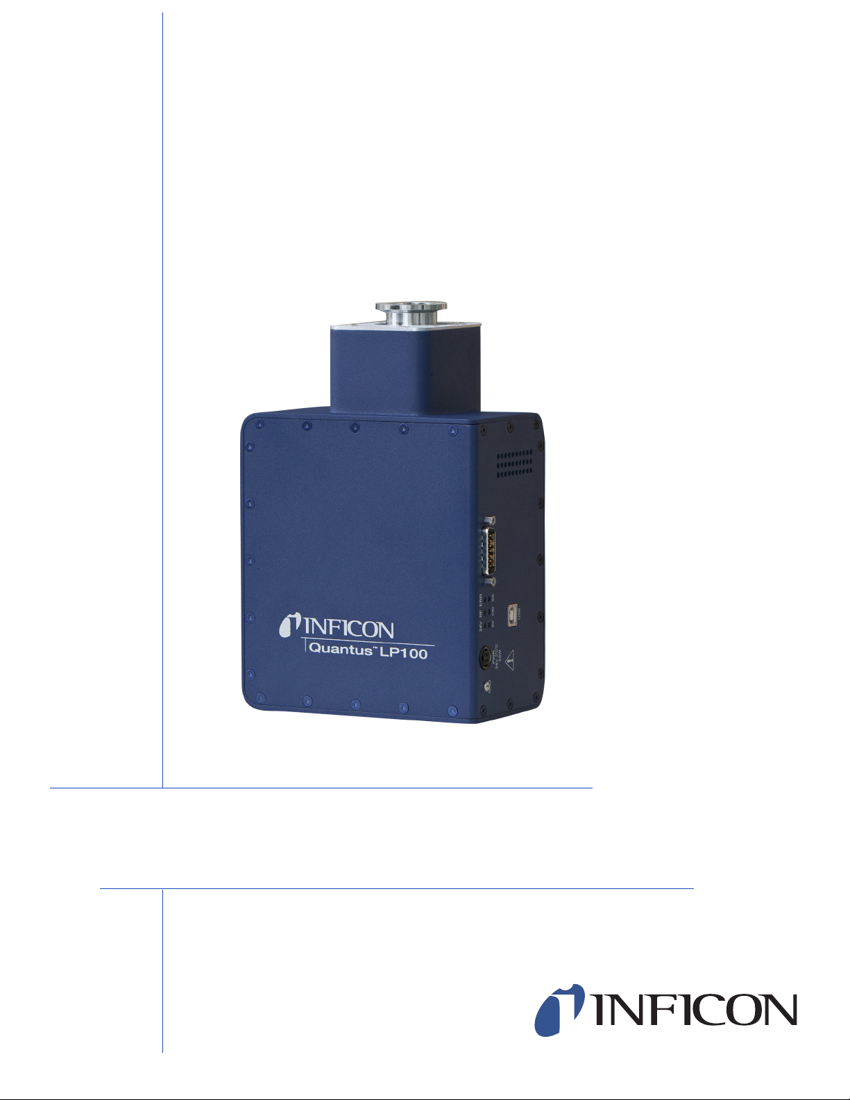
Quantus™LP100
Gas Analysis System
IPN 074-510-P1B


www.inficon.com [email protected]
Due to our continuing program of product improvements, specifications are subject to change without notice.
©2011 INFICON
®
OPERATING MANUAL
Quantus™LP100
Gas Analysis System
IPN 074-510-P1B

Trademarks
The trademarks of the products mentioned in this manual are held by the companies that
produce them.
INFICON®, FabGuard® and Quantus™ are trademarks of INFICON GmbH.
Oracle® and Java™ are registered trademarks of Oracle and/or its affiliates.
Windows®, is a registered trademarks of Microsoft Corporation.
All other brand and product names are trademarks or registered trademarks of their respective companies.
Disclaimer
The information contained in this manual is believed to be accurate and reliable. However, INFICON assumes
no responsibility for its use and shall not be liable for any special, incidental, or consequential damages related
to the use of this product.
Due to our continuing program of product improvements, specifications are subject to change without notice.
Copyright
©2011 All rights reserved.
Reproduction or adaptation of any part of this document without permission is unlawful.

WARRANTY AND LIABILITY - LIMITATION: Seller warrants the products
manufactured by it, or by an affiliated company and sold by it, and described on
the reverse hereof, to be, for the period of warranty coverage specified below, free
from defects of materials or workmanship under normal proper use and service.
The period of warranty coverage is specified for the respective products in the
respective Seller instruction manuals for those products but shall not be less than
one (1) year from the date of shipment thereof by Seller. Seller's liability under this
warranty is limited to such of the above products or parts thereof as are returned,
transportation prepaid, to Seller's plant, not later than thirty (30) days after the
expiration of the period of warranty coverage in respect thereof and are found by
Seller's examination to have failed to function properly because of defective
workmanship or materials and not because of improper installation or misuse and
is limited to, at Seller's election, either (a) repairing and returning the product or
part thereof, or (b) furnishing a replacement product or part thereof, transportation
prepaid by Seller in either case. In the event Buyer discovers or learns that a
product does not conform to warranty, Buyer shall immediately notify Seller in
writing of such non-conformity, specifying in reasonable detail the nature of such
non-conformity. If Seller is not provided with such written notification, Seller shall
not be liable for any further damages which could have been avoided if Seller had
been provided with immediate written notification.
THIS WARRANTY IS MADE AND ACCEPTED IN LIEU OF ALL OTHER
WARRANTIES, EXPRESS OR IMPLIED, WHETHER OF MERCHANTABILITY OR
OF FITNESS FOR A PARTICULAR PURPOSE OR OTHERWISE, AS BUYER'S
EXCLUSIVE REMEDY FOR ANY DEFECTS IN THE PRODUCTS TO BE SOLD
HEREUNDER. All other obligations and liabilities of Seller, whether in contract or
tort (including negligence) or otherwise, are expressly EXCLUDED. In no event
shall Seller be liable for any costs, expenses or damages, whether direct or
indirect, special, incidental, consequential, or other, on any claim of any defective
product, in excess of the price paid by Buyer for the product plus return
transportation charges prepaid.
No warranty is made by Seller of any Seller product which has been installed,
used or operated contrary to Seller's written instruction manual or which has been
subjected to misuse, negligence or accident or has been repaired or altered by
anyone other than Seller or which has been used in a manner or for a purpose for
which the Seller product was not designed nor against any defects due to plans or
instructions supplied to Seller by or for Buyer.
This manual is intended for private use by INFICON® Inc. and its customers.
Contact INFICON before reproducing its contents.
NOTE: These instructions do not provide for every contingency that may arise in
connection with the installation, operation or maintenance of this equipment.
Should you require further assistance, please contact INFICON.
Warranty
www.inficon.com [email protected]


TOC - 1
IPN 074-510-P1B
Quantus LP100 Operating Manual
Table Of Contents
Trademarks
Disclaimer
Copyright
Chapter 1
Introduction
1.1 System Overview . . . . . . . . . . . . . . . . . . . . . . . . . . . . . . . . . . . . . . . . . . . . . 1-1
1.2 Safety . . . . . . . . . . . . . . . . . . . . . . . . . . . . . . . . . . . . . . . . . . . . . . . . . . . . . . 1-1
1.2.1 Definition of Notes, Cautions and Warnings. . . . . . . . . . . . . . . . . . . . . . . . . 1-1
1.2.2 Before You Begin . . . . . . . . . . . . . . . . . . . . . . . . . . . . . . . . . . . . . . . . . . . . . 1-2
1.2.3 General Warnings and Cautions . . . . . . . . . . . . . . . . . . . . . . . . . . . . . . . . . 1-2
1.3 Terminology . . . . . . . . . . . . . . . . . . . . . . . . . . . . . . . . . . . . . . . . . . . . . . . . . 1-3
1.4 How To Contact Customer Support . . . . . . . . . . . . . . . . . . . . . . . . . . . . . . . 1-4
1.4.1 Returning Your Instrument to INFICON . . . . . . . . . . . . . . . . . . . . . . . . . . . . 1-4
1.5 Purpose of the Quantus LP100 Gas Analysis System . . . . . . . . . . . . . . . . . 1-5
1.6 Computer System Requirements . . . . . . . . . . . . . . . . . . . . . . . . . . . . . . . . . 1-5
1.7 Operating System Requirements . . . . . . . . . . . . . . . . . . . . . . . . . . . . . . . . . 1-5
1.8 Description of the Quantus LP100 . . . . . . . . . . . . . . . . . . . . . . . . . . . . . . . . 1-5
1.8.1 Introduction. . . . . . . . . . . . . . . . . . . . . . . . . . . . . . . . . . . . . . . . . . . . . . . . . . 1-5
1.8.2 LP100 Sensor Overview. . . . . . . . . . . . . . . . . . . . . . . . . . . . . . . . . . . . . . . . 1-6
1.8.3 LP100 Microplasma Sensor Cell . . . . . . . . . . . . . . . . . . . . . . . . . . . . . . . . . 1-7
1.8.4 LP100 Electronic Control Module . . . . . . . . . . . . . . . . . . . . . . . . . . . . . . . . . 1-7
1.9 AUX I/O Connector. . . . . . . . . . . . . . . . . . . . . . . . . . . . . . . . . . . . . . . . . . . . 1-8
1.9.1 Auxiliary I/O Specifications. . . . . . . . . . . . . . . . . . . . . . . . . . . . . . . . . . . . . . 1-8
1.9.1.1 Mechanical . . . . . . . . . . . . . . . . . . . . . . . . . . . . . . . . . . . . . . . . . . . . . . . . . . 1-8
1.9.1.2 Electrical. . . . . . . . . . . . . . . . . . . . . . . . . . . . . . . . . . . . . . . . . . . . . . . . . . . . 1-8
1.9.1.2.1 Digital I/O . . . . . . . . . . . . . . . . . . . . . . . . . . . . . . . . . . . . . . . . . . . . . . . . . . . 1-8
1.9.1.2.2 Relay . . . . . . . . . . . . . . . . . . . . . . . . . . . . . . . . . . . . . . . . . . . . . . . . . . . . . . 1-8
1.9.1.2.3 Valve Driver . . . . . . . . . . . . . . . . . . . . . . . . . . . . . . . . . . . . . . . . . . . . . . . . . 1-8
1.9.2 Auxiliary I/O Pin Designations . . . . . . . . . . . . . . . . . . . . . . . . . . . . . . . . . . . 1-8
1.10 Quantus LP100 Specifications . . . . . . . . . . . . . . . . . . . . . . . . . . . . . . . . . . . 1-9

TOC - 2
IPN 074-510-P1B
Quantus LP100 Operating Manual
Chapter 2
Theory
2.1 Introduction to Optical Emission Spectroscopy . . . . . . . . . . . . . . . . . . . . . . 2-1
2.2 Origin of Optical Emission Theory . . . . . . . . . . . . . . . . . . . . . . . . . . . . . . . . 2-1
2.3 Complex Optical Emission Spectra . . . . . . . . . . . . . . . . . . . . . . . . . . . . . . . 2-3
2.3.1 Increasing Numbers of Electrons . . . . . . . . . . . . . . . . . . . . . . . . . . . . . . . . . 2-3
2.3.2 Molecular Combinations of Atoms . . . . . . . . . . . . . . . . . . . . . . . . . . . . . . . . 2-4
2.4 Quantus and Optical Emission Spectroscopy . . . . . . . . . . . . . . . . . . . . . . . 2-4
Chapter 3
Installation
3.1 Installation of the Quantus LP100 . . . . . . . . . . . . . . . . . . . . . . . . . . . . . . . . 3-1
3.1.1 LP100 Installation Requirements . . . . . . . . . . . . . . . . . . . . . . . . . . . . . . . . . 3-1
3.1.1.1 LP100 Dimensions . . . . . . . . . . . . . . . . . . . . . . . . . . . . . . . . . . . . . . . . . . . . 3-1
3.1.2 Installation Comments . . . . . . . . . . . . . . . . . . . . . . . . . . . . . . . . . . . . . . . . . 3-2
3.1.3 Cleaning . . . . . . . . . . . . . . . . . . . . . . . . . . . . . . . . . . . . . . . . . . . . . . . . . . . . 3-3
3.1.4 Connecting the USB Interface . . . . . . . . . . . . . . . . . . . . . . . . . . . . . . . . . . . 3-3
3.2 LP100 Installation. . . . . . . . . . . . . . . . . . . . . . . . . . . . . . . . . . . . . . . . . . . . . 3-4
Chapter 4
Operation
4.1 Introduction. . . . . . . . . . . . . . . . . . . . . . . . . . . . . . . . . . . . . . . . . . . . . . . . . . 4-1
4.2 Sensor Status LEDs . . . . . . . . . . . . . . . . . . . . . . . . . . . . . . . . . . . . . . . . . . . 4-1
4.2.1 Descriptions of Sensor Status LEDs . . . . . . . . . . . . . . . . . . . . . . . . . . . . . . 4-1
4.3 Spread-Spectrum (SS) . . . . . . . . . . . . . . . . . . . . . . . . . . . . . . . . . . . . . . . . . 4-2
Chapter 5
Accessories and Spare Parts
5.1 LP100 Spare Parts. . . . . . . . . . . . . . . . . . . . . . . . . . . . . . . . . . . . . . . . . . . . 5-1
5.2 LP100 Accessories. . . . . . . . . . . . . . . . . . . . . . . . . . . . . . . . . . . . . . . . . . . . 5-1
5.2.1 USB to Ethernet Kit . . . . . . . . . . . . . . . . . . . . . . . . . . . . . . . . . . . . . . . . . . . 5-1
5.2.2 Isolation Valve Kit. . . . . . . . . . . . . . . . . . . . . . . . . . . . . . . . . . . . . . . . . . . . . 5-1
Chapter 6
Maintenance
6.1 Introduction. . . . . . . . . . . . . . . . . . . . . . . . . . . . . . . . . . . . . . . . . . . . . . . . . . 6-1
6.2 Replacing the Microplasma Sensor Cell (MSC) . . . . . . . . . . . . . . . . . . . . . . 6-1

1 - 1
IPN 074-510-P1B
Quantus LP100 Operating Manual
Chapter 1
Introduction
1.1 System Overview
INFICON Quantus™LP100 gas analysis system operates using the principal of
optical emission spectroscopy. A gas sample or gas-flow of interest is presented to
a proprietary Microplasma Sensor Cell inside the sensor that excites the gas,
causing it to produce a plasma. The light emitted by the plasma has a spectrum
that provides information about the atoms and molecules present. The optical
emission is detected by a spectrometer inside the sensor. The resulting spectra are
analyzed by INFICON FabGuard™analysis software on a control computer.
1.2 Safety
The LP100 generates high voltages, radio-frequency signals, and light (ultra-violet,
visible, and infrared light). Aside from a field-replaceable Microplasma Sensor Cell,
the LP100 has no user-serviceable parts.
WARNING
To prevent injury, and to prevent voiding the factory
warranty, repairs to the LP100 should only be performed
by factory-authorized personnel.
1.2.1 Definition of Notes, Cautions and Warnings
When using this manual, please pay attention to the NOTES, CAUTIONS and
WARNINGS found throughout. For the purposes of this manual they are defined as
follows:
NOTE: Pertinent information that is useful in achieving maximum instrument
efficiency when followed.
CAUTION
Failure to heed these messages could result in damage
to the instrument.
WARNING
Failure to heed these messages could result in personal
injury.
1 - 2
IPN 074-510-P1B
Quantus LP100 Operating Manual
1.2.2 Before You Begin
1REVIEW the installation process thoroughly before beginning work.
2CONFIRM that the sensor materials of construction and surfaces are
compatible with the exposed process environment.
3CONFIRM that the sensor is installed in an approved manner.
1.2.3 General Warnings and Cautions
WARNING
NEVER operate the sensor without its protective
enclosures. The sensor should only be powered when
fully mounted using the KF vacuum flange interface to an
appropriate system to be monitored.
WARNING
NEVER install or power the sensor in a position where a
user can physically access, or view directly the
microplasma.
WARNING
NEVER touch the microplasma source or its assembly
within its containment cavity.
WARNING
NEVER view directly the microplasma discharge.
CAUTION
NEVER operate the sensor when the interior of the
microplasma sensor cell is exposed to ambient or other
sources of light such as other processes.

1 - 3
IPN 074-510-P1B
Quantus LP100 Operating Manual
CAUTION
NEVER prevent airflow by blocking the vent holes or the
cooling fan on the sensor. Unpredictable results or
damage to the sensor may result.
CAUTION
NEVER power the sensor with an unapproved power
supply.
1.3 Terminology
In describing the use of the sensor in this guide, the following terms will be used:
Sensor: A complete LP100 sensor that includes an Electronic Control Module
(ECM) and Microplasma Sensor Cell (MSC).
Electronic Control Module (ECM): The ECM contains a spectrometer and
electronics. This unit is powered by a 24 V (dc) 2.5 A supply.
Microplasma Sensor Cell (MSC): The MSC contains the microplasma light
source. The MSC is field-replaceable.
Software: Quantus is operated by INFICON FabGuard analysis software running
on an INFICON FabGuard Controller or Windows®-based PC.
Controller: The computer running INFICON FabGuard analysis software to
operate Quantus is an INFICON FabGuard Controller or Windows-based PC.
Tool or Process Tool: A process tool or other system onto which the sensor is
attached. The sensor should only be used when properly installed onto an
appropriate vacuum system or process tool.

1 - 4
IPN 074-510-P1B
Quantus LP100 Operating Manual
1.4 How To Contact Customer Support
Worldwide support information regarding:
Technical Support, to contact an applications engineer with questions
regarding INFICON products and applications, or
Sales and Customer Service, to contact the INFICON Sales office nearest you,
or
Repair Service, to contact the INFICON Service Center nearest you,
is available at www.inficon.com.
If you are experiencing a problem with your instrument, please have the following
information readily available:
the serial number for your instrument,
a description of your problem,
an explanation of any corrective action that you may have already attempted,
and the exact wording of any error messages that you may have received.
To contact Customer Support, see Support at www.inficon.com.
1.4.1 Returning Your Instrument to INFICON
Do not return any component of your instrument to INFICON without first speaking
with a Customer Support Representative. You must obtain a Return Material
Authorization (RMA) number from the Customer Support Representative.
If you deliver a package to INFICON without an RMA number, your package will be
held and you will be contacted. This will result in delays in servicing your
instrument.
Prior to being given an RMA number, you will be required to complete a Declaration
Of Contamination (DOC) form to identify what process materials your instrument
has been exposed. DOC forms must be approved by INFICON before an RMA
number is issued. INFICON may require that the instrument be sent to a
designated decontamination facility, not to the factory.

1 - 5
IPN 074-510-P1B
Quantus LP100 Operating Manual
1.5 Purpose of the Quantus LP100 Gas Analysis System
The Quantus LP100 detects changes in gas characteristics such as composition,
pressure or concentration. Detecting such changes allows the user to detect leaks,
contaminants and process endpoints in critical process environments.
1.6 Computer System Requirements
The Quantus gas analysis system utilizes INFICON FabGuard analysis software
with the following computer system requirements.
1.7 Operating System Requirements
INFICON FabGuard analysis software requires Windows XP Operating System or
higher.
Quantus requires the Java™Runtime Engine, Version 6. Many computers already
have the Java Runtime Engine installed. If necessary, the Java Runtime Engine
can be downloaded from www.java.com. Note that 32-bit operating systems
require the 32-bit Java Runtime Engine, while 64-bit operating systems require the
64-bit Java Runtime Engine.
1.8 Description of the Quantus LP100
1.8.1 Introduction
The INFICON Quantus LP100 gas analysis system is designed for monitoring
changes in gas composition over the pressure range of 10 mTorr to 1 Torr, including
many corrosive gas environments. In some cases, the LP100 may function beyond
this pressure range. However, the ability to ignite plasma may be affected by the
species of gas present. Therefore, the pressure range for plasma ignition, or for
sustaining the plasma, may be greater or lesser depending on the application. For
application specific support, please contact your nearest INFICON representative.
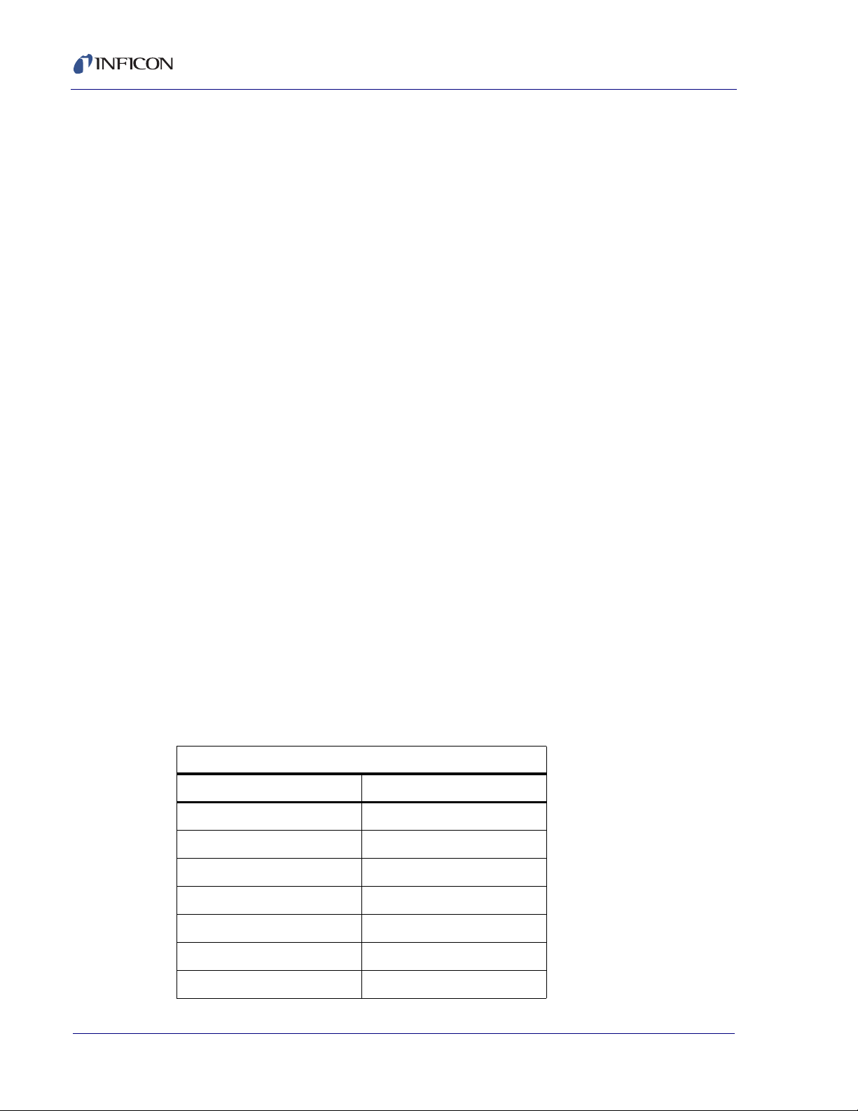
Table 1-1 Computer System Requirements
Minimum Requirement Recommended
Processor Intel Pentium 4, 3 GHz Intel Core 2 or greater
Memory 1 GB 2 GB or greater
Hard Drive 80 GB 160 GB or greater
Resolution 15" (1024 x 768) 17" (1280 x 1024)
1 - 6
IPN 074-510-P1B
Quantus LP100 Operating Manual
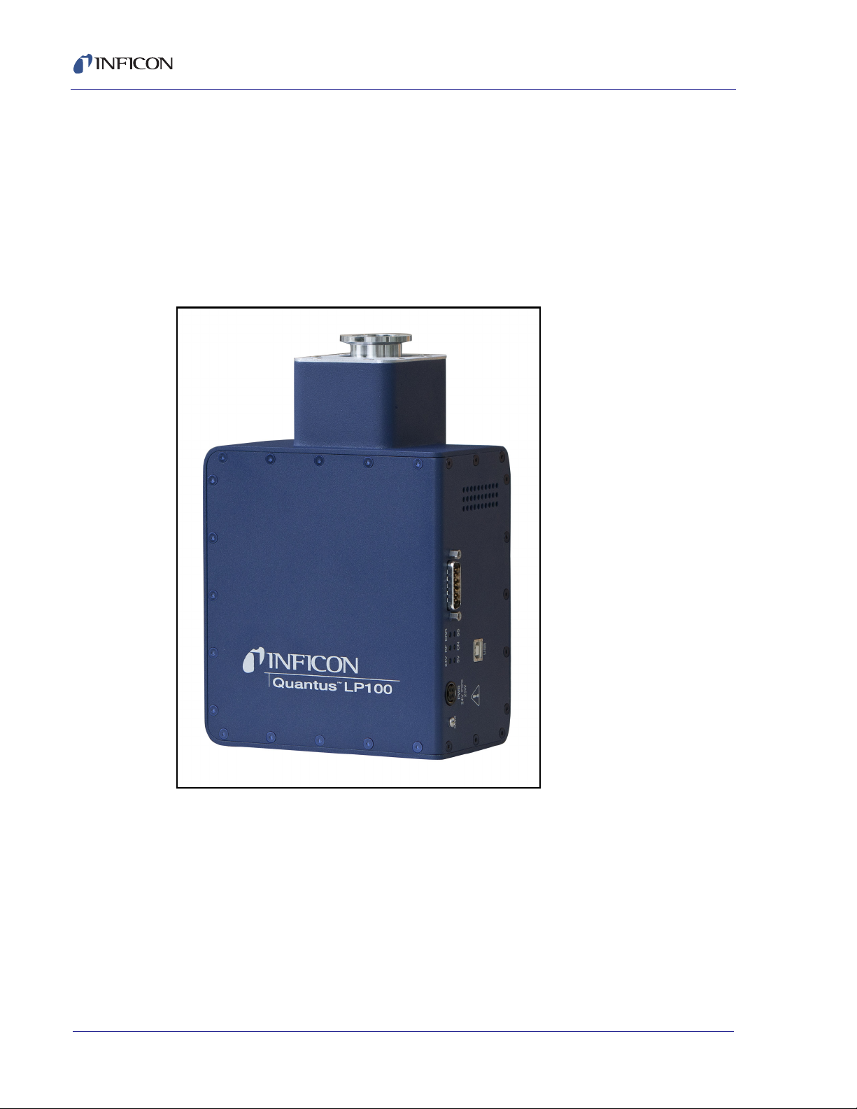
1.8.2 LP100 Sensor Overview
The LP100 (Figure 1-1) is designed for applications that operate between 0.01 and
1 Torr. Exact pressure range is application dependent. Range of 0.01 to 1 Torr is
tested with argon. The LP100 is designed and manufactured to withstand exposure
to corrosive and aggressive gases such as Chlorine, Fluorine and other chemicals.
The LP100 has two main sections, an Electronic Control Module (ECM) and a
Microplasma Sensor Cell (MSC). The ECM occupies the larger portion of the
housing while the MSC occupies the smaller portion of the housing.
Figure 1-1 LP100

1 - 7
IPN 074-510-P1B
Quantus LP100 Operating Manual
1.8.3 LP100 Microplasma Sensor Cell
Figure 1-2 LP100 Microplasma Sensor Cell
The Quantus LP100 creates a plasma by coupling energy into the gas utilizing a
patented planar antenna in the Microplasma Sensor Cell. The antenna is protected
by a sapphire window so it is not exposed to the process chamber or gas sample.
This provides the LP100 its unique operating capabilies that allow the sensor to
operate in corrosive and aggressive environments. The planar antenna is built
using PCB techniques that provide tight tolerances and high performance. The
Microplasma Sensor Cell can be replaced in the field.
1.8.4 LP100 Electronic Control Module
The Electronic Control Module includes an optical spectrometer and control
electronics. It is powered by a 24 V (dc) power supply, has a cooling fan and six
status LEDs. Primary communication is through a USB port. Auxiliary I/O is
available through a 15-pin D-sub connector.
1 - 8
IPN 074-510-P1B
Quantus LP100 Operating Manual
1.9 AUX I/O Connector
1.9.1 Auxiliary I/O Specifications
1.9.1.1 Mechanical
15-pin D-sub male connector used on Electronic Control Module. 15-pin D-sub
female mating connector required.
1.9.1.2 Electrical
1.9.1.2.1 Digital I/O
Signals I/O 0 to I/O 3 can be set or read by the Quantus. These four (input or
output) bi-directional auto-sensing level shifters are TTL-compatible I/O
connections rated for 0 to 5V (dc) with 10 k-ohm pull-up impedance. As digital
output connections, each can source a maximum of 0.5 mA. As digital input
connections, each can sink a maximum of 1.0 mA. The user is responsible for
limiting the input current to the 1.0 mA maximum.
1.9.1.2.2 Relay
A contact closure relay, single-pole double-throw (SPDT) is included in the
Quantus Electronic Control Module. Maximum current is 0.5 A, maximum voltage
is 50 V (ac). The relay is controlled by FabGuard software. The normal (inactive)
state is electrical continuity between pins 1 and 3, pin 2 open. The active state
switches to continuity between pins 2 and 3, pin 1 open.
1.9.1.2.3 Valve Driver
24 V Valve Driver, powered by the Quantus Electronic Control Module and
controlled by FabGuard software. Valve is open when circuit is active, which is
when pin 7 is grounded by the Quantus Electronic Control Module.
1.9.2 Auxiliary I/O Pin Designations
Table 1-2 AUX I/O Pin Designations
AUX I/O 15-pin D-sub Connector
Pin # Signal
1RelayNC
2RelayNO
3 Relay Common
4 I/O 2
5 I/O 1
6 I/O 0
7 Valve Control Return

1 - 9
IPN 074-510-P1B
Quantus LP100 Operating Manual
1.10 Quantus LP100 Specifications
Table 1-3 details the specifications for the Quantus LP100 gas analysis system. As
a result of the continuous product improvement and quality assurance programs in
place at INFICON, these specifications are subject to change without notice or
obligation.
NOTE: All specifications are measured after a 1 hour warm-up period.
8 Valve + 24 VDC
9 I/O 3
10 No Connection
11 No Connection
12 GND
13 GND
14 GND
15 GND
Table 1-2 AUX I/O Pin Designations (continued)
AUX I/O 15-pin D-sub Connector
Pin # Signal
Table 1-3 Quantus LP100 Specifications
Parameters LP100
Performance
Technology Optical Emission Spectroscopy using proprietary
and integrated ICP microplasma, spectrometer
and RF power supply
Spectrometer Performance 200 to 850 nm wavelengths (UV-Vis)
16-bit full-scale resolution, 2048 pixels
Integration Time Minimum of 1ms
Detection Limit To low PPM levels
(Application dependent)
Gas Sampling Interface
Process Environment 10.01 to 1 Torr
(Application dependent)
Vacuum Fitting KF25
Maximum Flange Temp 80°C

1 - 10
IPN 074-510-P1B
Quantus LP100 Operating Manual
Serviceability Sensor Cell is field replaceable
Facilities
Operating Temp Range 0-50°C (non-condensing, Sensor Cell 80°C)
Power Requirements 24 V (dc) @ 2.5 A (AC/DC converter provided)
Power Consumption < 25 Watts (typical, steady-state operation)
Carrier Gases None required
Mounting Options Direct Mount via KF25 Flange
Approximate Dimensions and Weight
Dimensions 3.4" H x 5.9" W x 9.5" L
(87 mm x 15 1mm x 241 mm)
Weight 5.9 lbs. (2.7 kg)
1Pressure range for argon. Pressure range may differ per application.
Table 1-3 Quantus LP100 Specifications (continued)
Parameters LP100
Table of contents
Other Inficon Test Equipment manuals

Inficon
Inficon MPG400 User manual

Inficon
Inficon E-Check Quick guide

Inficon
Inficon 122 20 User manual

Inficon
Inficon 122 20 Quick guide

Inficon
Inficon ULTRATEST UL3000 Fab PLUS User manual

Inficon
Inficon TC1000 User manual

Inficon
Inficon MCT150 User manual

Inficon
Inficon TGF10 User manual

Inficon
Inficon FTC3000 Quick guide

Inficon
Inficon TL3-5 User manual


