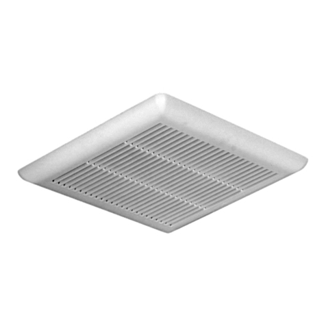
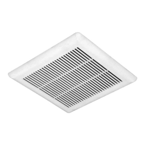
Aria QBV080 User manual

OWNER’S MANUAL
MANUEL DE L’UTILISATEUR
MANUAL DEL USARIO
ULTRA QUIET BATHROOM EXHAUST FAN
VENTILATEUR ULTRA SILENCIEUX POUR SALLE DE BAIN
VENTILADOR ULTRA SILENCIOSO PARA CUARTO DE BAÑO
PLEASE READ AND SAVE THESE INSTRUCTIONS • INSTALLER: PLEASE LEAVE THIS GUIDE WITH THE HOME OWNER.
LISEZ ET CONSERVEZ CES INSTRUCTIONS • INSTALLATEUR: LAISSEZ CE GUIDE AU PROPRIÉTAIRE.
LEA Y GUARDE ESTAS INSTRUCCIONES • INSTALADOR: ENTREGUE ESTA GUÍA AL PROPIETARIO DE LA VIVIENDA.
QBV080
REV.20191223

QBV080 2
ENGLISH
Table of Contents
Safety Information ..................................2
Warranty
One Year Limited Warranty...........................3
Warranty Claim Procedure ...........................3
Pre-Installation
Tools/Materials Required ............................4
Package Contents .................................5
Typical Installation .................................6
Installation ........................................7
Operation. . . . . . . . . . . . . . . . . . . . . . . . . . . . . . . . . . . . . . . . . 12
Care and Cleaning .................................12
Troubleshooting ...................................13
Specications
Wiring Diagram ..................................14
External Diagram of Fan Unit........................14
Service Parts......................................15
MANUEL DE L’UTILISATEUR ..........................16
MANUAL DEL USARIO ...............................30
Safety Information
WARNING:
WARNING – TO REDUCE THE RISK OF FIRE, ELECTRIC SHOCK, OR
INJURY TO PERSONS, OBSERVE THE FOLLOWING:
1. Use this unit only in the manner intended by the manufacturer. If you
have questions, contact the manufacturer.
2. Before servicing or cleaning unit, switch power off at service panel
and lock the service disconnecting means to prevent power from
being switched on accidentally. When the service disconnecting
means cannot be locked, securely fasten a prominent warning device,
such as a tag, to the service panel.
3. Installation work and electrical wiring must be done by a qualied
person(s) in accordance with all applicable codes and standards,
including re-rated construction codes and standards.
4. Sufcient air is needed for proper combustion and exhausting of
gases through the ue (chimney) of fuel burning equipment to prevent
back drafting. Follow the heating equipment manufacturer’s guideline
and safety standards such as those published by the National Fire
Protection Association (NFPA), and the American Society for Heating,
Refrigeration and Air Conditioning Engineers (ASHRAE), and the local
code authorities.
5. When cutting or drilling into wall or ceiling, do not damage electrical
wiring and other hidden utilities.
6. Ducted fans must always be vented to the outdoors.
7. If this unit is to be installed over a tub or shower, it must be marked
as appropriate for the application and be connected to a GFCI (Ground
Fault Circuit Interrupter) – protected branch circuit.
8. This unit must be grounded.
9. Always unplug or disconnect the appliance from the power supply
before servicing.
10. To reduce the risk of re or electric shock, do not use this fan with any
solid-state speed control device.
11. Do not install ventilation fan in a ceiling thermally insulated to a value
greater than R40.
12. Use an ON/OFF switch to operate this ventilation fan. Use of speed
controls may damage the motor.
13. DO NOT INSTALL IN A WALL.
WARNING: The unit has sharp edges. Always wear safety
gloves during installation, cleaning, or servicing.
CAUTION!
For general ventilating use only. Do not use to exhaust hazardous or
explosive materials and vapors.
DO NOT install this unit onto an acoustic ceiling panel.
This product is designed for installation in ceilings up to a 12/12 pitch (45
degree angle). Duct connector must point up.
To avoid motor bearing damage and noisy, unbalanced impellers, keep
drywall spray and construction dust away from power unit.
Please read specication label on product for further information and
requirements.
COOKING AREA
Do not install above or inside this area
Cooking
Equipment
45˚ 45˚
Floor

3 CONGLOMKB.COM
Please contact cs@conglomkb.com or 1-877-333-0098 for further assistance.
ENGLISH
Warranty
ONE YEAR LIMITED WARRANTY
A thorough inspection must be made before installation and any damage must be promptly reported. We will not be liable for failures or
damage that could have been discovered or avoided by proper inspection and testing prior to installation.
Conglom Inc. warrants this product to be free from defects in materials or workmanship for one (1) year from the date of purchase. Proof of
purchase (original sales receipt) from the original consumer purchaser must be made available to Conglom Inc. for all warranty claims.
This warranty is non-transferable and shall be voided if the unit is removed from its initial installation or if it is not installed following
the manufacturer’s instructions. It does not apply in the event of product damage due to the use of other than genuine Conglom Inc.
replacement parts, (Replacement parts may be obtained by e-mail at cs@conglomkb.com or by calling 1-877-333-0098 between
8:30 am - 5:00 pm EST) installation error, abuse, misuse or improper care and maintenance (whether performed by a plumber, contractor,
service provider or member of the purchaser’s household). The warranty excludes damage due to aggressive air or water conditions, harsh
or abrasive cleaners and/or materials.
Under no circumstance shall we be held liable for personal injury or property damage resulting from improper installation or use of this
product. We will not be held liable for inconvenience caused by loss of use of this product, costs incurred for labour or materials, removal
and installation of replacement units, or any other incidental or consequential damages. Costs relating to obtaining access for repair or
replacement are the responsibility of the user.
Our obligation shall be limited to the repair or replacement of a unit (at our discretion) that may prove, by our sole examination, to be defective
under normal use and service during the warranty period.
Any failure of this product that is not traceable to a defect in material or workmanship is not covered by this warranty. These non-warrantable
items include, but are not limited to:
-Improper installation not in accordance with manufacturer’s instructions.
-Dents and/or scratches incurred during shipping, handling, or installation.
- Change in colour or nish due to chemical usage.
-Damage caused by failure to follow care and cleaning guidelines, including damage caused by the use of abrasive cleaners.
-Alterations made to the unit by the purchaser or installer.
- Damage caused by accidental impact, re, ood, freezing, and normal wear.
- Bends and warping caused by forced connections, over-tightened ttings, and inadequate support during installation.
This warranty does not extend to commercial and institutional installation or use.
WARRANTY CLAIM PROCEDURE
If a claimable defect occurs or replacement parts are needed, please contact our customer service team at cs@conglomkb.com or
1-877-333-0098 (Service available in English and French, Monday - Friday from 8:30 am - 5 pm, EST).
Before you make your call, please ensure that you have:
-Model number or description.
-Proof of sale.
-Details regarding the defect and/or part number.
-Name(s) and address(es) of the owner and/or installer.

QBV080 4
ENGLISH
Pre-Installation
TOOLS/MATERIALS REQUIRED (NOT SUPPLIED)
Measuring tape Utility knife Pencil
Aluminum foil tape Phillips screwdriver Needle nose
pliers
Safety gloves Electric drill Safety goggles
Drywall saw Pry bar Wood screws
Respiratory mask Cable clamp Flexible duct
connector*
Duct adapter*
*For best performance use 4" round metal ducting. Other ducting is acceptable but may impact performance. Use of existing metal
ducting will require a short exible duct connector. If your ducting is other than 4” in diameter, a duct adapter is required to make an air
tight connection.

5 CONGLOMKB.COM
Please contact cs@conglomkb.com or 1-877-333-0098 for further assistance.
ENGLISH
Pre-Installation (continued)
PACKAGE CONTENTS
Carefully check this product for damage and/or missing parts prior to installation. If there is any damage or if you are missing parts, do not
proceed with the installation. Report damage and/or missing parts immediately to our customer service team at cs@conglomkb.com or
1-877-333-0098 (Service available in English and French, Monday - Friday from 8:30 am - 5:00 pm EST). Please do not dispose of packaging
until you are satised with your new product.
A CB
DE F
G H I
C
L
Part Description Quantity
A Ventilation Fan 1
B Damper (attached to fan housing) 1
C Grille 1
D Installation Template and Dust Cover 1
EHanger Channels - Long 3
FHanger Channels - Short 1
G Drywall Clips 4
H Long Screws 4
I Short Screws 2

QBV080 6
ENGLISH
Pre-Installation (continued)
TYPICAL INSTALLATION
Roof Cap*
Wall Cap*
Elbows*
Aluminum
Foil Tape*
Power Cable*
Insulation*
Ventilation Fan
Round
or Flexible Duct
Connector*
* Not Included
or
Fig.1

7 CONGLOMKB.COM
Please contact cs@conglomkb.com or 1-877-333-0098 for further assistance.
ENGLISH
Installation
REPLACING AN EXISTING FAN
WARNING: Before removing the existing ventilation fan, switch
power off at service panel and lock the service disconnecting
means to prevent power from being switched on accidentally.
When the service disconnecting means cannot be locked,
securely fasten a prominent warning device, such as a tag, to
the service panel.
WARNING: Always wear safety goggles and gloves during
installation to prevent personal injury.
Center line
Center line
Installation
template (D)
Joist
Joist
Joist
Joist
Fig. 2
Fig. 3
Fig. 5
NOTE:
For new installations, please see “Securing the Fan to The Ceiling Joists
– Unnished Ceilings” section.
-Ensure the existing fan opening is smaller than the supplied
installation template so it can be enlarged to t the new fan if
required. Check to ensure the joist arrow indicated on the template is
oriented correctly. It should be pointing towards the ceiling joist.
- Mark the center line of the existing fan opening as shown in gure 2.
-Align the provided installation template with the joist side and center
line, then draw along the template perimeter. See gure 3.
-Using a utility knife, score the ceiling along the perimeter.
NOTE:
It is recommended that you wear a respiratory mask when cutting the
drywall and removing the old fan.
-Check to make sure the power to your existing fan has been switched
off at the service panel.
-Cut the new opening in the ceiling using a drywall saw. Be careful
not to damage the existing venting or electrical wiring. See gure 4.
-Disconnect existing ductwork and electrical wiring.
-Remove the old fan along with any installation hardware. Use a pry
bar if necessary. Once your old fan has been removed, you are ready
to install your new ventilation fan. See gure 5.
Fig. 4

QBV080 8
ENGLISH
Installation (continued)
PREPARING THE NEW FAN
WARNING: It is recommended that you wear safety gloves
when handling the ventilation fan because it has sharp edges
that could cause injury.
- Unplug the motor from the receptacle. See gure 6.
-Remove the three screws securing the motor mounting
assembly to the fan housing and take the assembly out. See
gure 7.
-Unscrew the screw securing the electrical wiring junction
cover and slide the cover upwards to remove it. See gure 8.
CONNECTING THE ELECTRICAL WIRING
WIRING CONNECTION REQUIREMENTS
OBSERVE ALL GOVERNING CODES AND ORDINANCES
1. Electrical grounding is required for this ventilation fan. Check
with qualied electrician if you are not sure whether the
ventilation fan is properly grounded.
2. Failure to follow electrical requirements may result in a re.
3. A fuse in the neutral or grounding circuit could result in
electrical shock.
4. If the hot/cold water pipe is interrupted by plastic nonmetallic
gaskets or other materials, DO NOT use for grounding.
5. DO NOT GROUND TO A GAS PIPE.
6. Save installation instructions for electrical inspector’s use.
7. If codes permit and a separate ground wire is used, it is
recommended that a qualied electrician determine if the
ground path is adequate.
8. DO NOT use an extension cord or adapter plug with this
appliance.
9. The ventilation fan must be connected with copper wire only.
Electrical Wiring
Junction Cover
Fig. 6
Fig. 7
Fig. 8

9 CONGLOMKB.COM
Please contact cs@conglomkb.com or 1-877-333-0098 for further assistance.
ENGLISH
Installation (continued)
10. The ventilation fan should be connected directly to the switch
through exible, armoured or nonmetallic sheathed copper cable.
Allow some slack in the cable so the appliance can be moved if
servicing is ever necessary.
11. A UL listed or CSA approved conduit connector must be provided
at each end of the power supply cable.
12. Wire size must conform to all local codes and ordinances. The
latest edition requirements of the National Electrical Code ANSI/
NFPA 70, or the latest edition CSA Standards C22.1-94, Canadian
Electrical Code Part 1 and C22.2 No. 0-M91.
WARNING – TO REDUCE THE RISK OF FIRE, ELECTRIC
SHOCK, OR INJURY TO PERSONS, OBSERVE THE
FOLLOWING: Installation work and electrical wiring must be
done by qualified person(s) in accordance with all applicable
codes and standards, including fire-rated construction.
DANGER: Risk of electrical shock. This ventilation fan must be
properly grounded.
DANGER: Turn off the power circuit breaker or the power switch
on the junction box before installing this unit. Touching circuitry
inside the ventilation fan while it is energized will result in
death or serious injury.
DANGER: All electrical wiring must be properly installed,
insulated, and grounded. Improper insulation and grounding
will result in deadly electrical shock.
IMPORTANT:
It is the customer’s responsibility to contact a qualified electrical
installer and ensure that the electrical installation is adequate and complies with
the National Electrical Code, or CSA standards, as well as all local codes and
ordinances.
-Install a cable clamp (not supplied) to the wiring hole of the
fan housing in either of the two available locations as shown in
gure 9.
-Feed the electrical supply cable through the cable clamp. See
gure 9.
-Use UL approved connectors to connect the fan wires to your
electrical supply cable as shown in gure 10.
-Tighten the cable clamp to secure the electrical supply cable.
-Reinstall the electrical wiring junction cover to the fan housing
ensuring all wiring connections are fully enclosed. See gure 11.
Fan Housing
Switch Box
120 VAC Line In
ON/OFF Switch
(Not Supplied)
= Black
= White
= Ground (Bare)
Electrical Wiring
Junction Cover
Fan Housing
Cable Clamp
Cable Clamp
Fig. 10
Fig. 9
Fig. 11

QBV080 10
ENGLISH
Installation (continued)
CONNECTING THE DUCT
NOTE:
For best performance, connect ducting using the shortest and straightest
possible route. Avoid installing with ducts smaller than the fan's damper. Using
flexible duct connector is recommended for the quietest possible installation. If
rigid duct is to be used, having a 1-3 feet section of flexible ducting will allow for a
quiet installation.
-Pull existing ducting through the ceiling opening. If
existing ducting is metal you will require a short exible
duct connector. Rigid duct may need to be cut for proper
installation.
-Position the fan housing assembly properly and secure
existing ducting to the fan's damper.
- If using a exible duct connector or duct adapter, use
aluminum foil tape at each end to secure the connector or
adapter to the existing ducting and to the fan's damper. See
gure 12.
-Ensure that the fan's damper is unobstructed and able to
swivel freely.
If you are replacing an existing fan then proceed to “Securing
the Fan – Finished Ceilings” section.
If this is a new installation and your ceiling is unnished,
proceed to “Securing the Fan to The Ceiling Joists –
Unnished Ceilings” section.
SECURING THE FAN - FINISHED CEILINGS
DANGER: Turn off the power circuit breaker or the power switch
on the junction box before installing this unit. Touching circuitry
inside the ventilation fan while it is energized will result in
death or serious injury.
NOTE:
Ensure your fan is properly connected to the duct work and electrical
supply cable (not powered) before proceeding.
-To make this housing easier to insert into the ceiling opening,
bend the joist mounting tabs towards the housing as shown
in gure 13. The damper and duct can also be detached from
inside the housing as shown in gure 14.
-With the motor mounting assembly removed, gently insert the
fan housing into the fan opening in the ceiling. Position it such
that the housing is ush with the ceiling surface.
-Secure the fan housing to the ceiling joist with screws as
shown in gure 16.
-If the housing cannot be secured to the joists directly, you
may use the supplied drywall clips (G) to secure the fan
housing to the drywall directly as shown in gure 15.
-Ensure the housing is fastened securely, then reinstall the
motor mounting assembly. Plug the motor into the receptacle.
See gure 16.
If your ducting is other than 4” in
diameter, a duct adapter is required (not
supplied) to make an air tight connection.
Existing house
ducting
Duct adapter
Aluminum
foil tape
Duct adapter
(optional)
H
Clip (G)
Drywall
Fan Housing
Ceiling
drywall
Ceiling
opening
Screw holes
Joist
2
1
3
Fan
housing
Motor mounting
assembly
Motor receptacle
Fig. 12
Fig. 13 Fig. 14
Fig. 15
Fig. 16

11 CONGLOMKB.COM
Please contact cs@conglomkb.com or 1-877-333-0098 for further assistance.
ENGLISH
Installation (continued)
SECURING THE FAN TO THE CEILING JOIST -
UNFINISHED CEILINGS
DANGER: Turn off the power circuit breaker or the power switch
on the junction box before installing this unit. Touching circuitry
inside the ventilation fan while it is energized will result in
death or serious injury.
NOTE:
Ensure your fan is properly connected to the duct work and electrical
supply cable (not powered) before proceeding.
-Secure the ventilation fan to the ceiling joist in a
desired location. This fan offers several convenient
ways to secure the housing to your ceiling joists
(both conventional and I-joist). Choose the method
most appropriate to your ceiling construction as
shown in gures 17 through 19.
Joist Proles
-Reinstall motor mounting assembly. Plug the motor into the
receptacle. See gure 20.
-Power the fan to make sure everything is in proper working
order.
- Once you are satised with your installation, protect the fan
motor from construction dust and debris with the supplied
dust cover (D) until construction is completed. See gure 21.
Do not install the dust cover in nished construction. Do not
operate the fan with the dust cover in place as it will damage
the motor.
Joist
Fig. 20
NOTE:
Duct and electrical connections not shown for clarity.
I
I
H
H
H
H
I
H
H
E or F
Joist
C
L
Dust
cover (D)
H
H
H
H
Fig. 18
Fig. 21
Fig. 17
Fig. 19

QBV080 12
ENGLISH
Installation (continued)
INSTALLING THE GRILLE
-Squeeze the springs on the grille together, and insert the
springs into the slots of the housing assembly. Firmly push
the grille up against the ceiling. See gure 22.
Spring slot
Ceiling
Fig. 22
Operation
TURNING ON/OFF THE UNIT
-Use an external ON/OFF switch to operate this ventilation fan.
WARNING: To Reduce The Risk Of Fire Or Electric
Shock, Do Not Use This Fan With Any Solid-State
Speed Control Device.
Care and Cleaning
WARNING: Failure to maintain basic standards of care and cleaning of the ventilation fan increases the risk of fire, electric shock,
or injury to persons. Before servicing or cleaning unit, switch power off at service panel and lock the service disconnecting means
to prevent power from being switched on accidentally. When the service disconnecting means cannot be locked, securely fasten a
prominent warning device, such as a tag, to the service panel.
The ventilation fan should be cleaned regularly (internally and externally) to preserve its appearance and performance.
Do: Do Not:
-Use a dusting brush attachment to gently vacuum
the exterior and interior of the ventilation fan to
remove dust and debris.
-Do not let plaster dust or any other construction
residue enter the fan. During construction or
renovation, cover the fan.
-Combustible products used for cleaning such as
acetone, alcohol, ether, or benzol are highly explosive
and should never be used close to the fan.

13 CONGLOMKB.COM
Please contact cs@conglomkb.com or 1-877-333-0098 for further assistance.
ENGLISH
Troubleshooting
DANGER: Turn off the power circuit breaker or the power switch on the junction box before performing maintenance. Touching circuitry inside
the ventilation fan while it is energized may result in serious injury or death.
WARNING: Failure to maintain basic standards of care and cleaning of the ventilation fan increases the risk of fire, electric shock, or injury to
persons. Before servicing or cleaning unit, switch power off at service panel and lock the service disconnecting means to prevent power from
being switched on accidentally. When the service disconnecting means cannot be locked, securely fasten a prominent warning device, such as
a tag, to the service panel.
Problem Solution
The fan does not operate. -Check that the power supply cable and all electrical wiring are properly
connected.
-Check that the fan blade is not obstructed.
-Check that the power is turned on at the junction box or circuit breaker.
The fan vibrates when the fan is operating. -Check that the fan has been secured properly. Tighten into position, if
necessary.
-Check that the motor is secured in place. If not, then tighten the motor in place.
-Check that the fan is not damaged. If so, replace the fan.
The fan seems weak. -Check that the duct size used is of appropriate size. The fan will not function
efciently with insufcient duct size.
-Check that the duct is not clogged with debris and the tight mesh on the wall
cap, if applicable, is not restricting air ow.
-Check that the damper unit is opening properly.
-Check that no birds or animals have nested in the duct.
The fan is not venting properly. -Reduce the length of duct work and the number of elbows if necessary. Ensure
that all joints are properly connected, sealed, and taped.
-Check that the duct does not open against the wind.
The fan is making excessive noise. -Check to make sure there is nothing blocking the fan blade.
-The fan motor is permanently lubricated and does not need to be oiled or
lubricated. If the motor bearings are making excessive or unusual noises they
should be replaced. The fan blade should also be replaced at that time.
-Check to make sure that the fan's damper can pivot freely and is not
obstructed.
-Check to make sure the damper in the wall or roof cap can pivot freely and is
not obstructed.

QBV080 14
ENGLISH
Specications
Model QBV080
Air Delivery (CFM - Cubic Feet Per Minute) 80 ±10%
Lound Level (Sones) 0.3
Duct Size 4" (10.2 cm)
Motor Power (W) 18
Voltage / Frenquency 120 VAC / 60Hz
Housing Dimensions 9" x 9" x 5 3/4" (22.9 cm x 22.9 cm x 14.6 cm)
Grille Dimensions 11 13/16"×11 7/16" (30 cm x 29.1 cm)
Net Weight (Kg) 2.83
WIRING DIAGRAM
Black
Black
White
Ground
White
Ground
Switch Unit
FAN
EXTERNAL DIAGRAM OF FAN UNIT
9"
(22.9 cm) 9"
(22.9 cm)
5 3/4"
(14.6 cm)
11 13/16"
(30 cm)
11 7/16"
(29.1 cm)

15 CONGLOMKB.COM
Please contact cs@conglomkb.com or 1-877-333-0098 for further assistance.
ENGLISH
Service Parts
If you are missing parts or if you require replacement parts, please contact our customer service team at cs@conglomkb.com or
1-877-333-0098 (8:30 am – 5 pm, EST, Monday–Friday). Identify the required part(s) and have the part number(s) ready.
A B C
D E
F G H
Part Description Code Quantity
A Motor QHB181 1
B Fan Blade QHB190 1
C Damper QHB192 1
D Grille QHB178 1
E Motor Bracket QHB185 1
F Hanger Channel Set QHB194 1
G Drywall Clips QHB196 4
H Hardware Pack QHB197 1

Imported by / Importé par / Importado por :
St-Laurent, Québec, H4S 2C3
(service available in English and French, Monday - Friday from 8:30 am - 5 pm EST)
(service disponible en anglais et français, du lundi au vendredi, 8h30 à 17h, H.N.E.)
(servicio disponible en inglés y francés, de lunes a viernes, de 8:30 am a 5:00 pm, hora del Este )
www.conglomkb.com
Table of contents
Other Aria Fan manuals
