Aria QR841 User manual

# QR841
OWNER’S MANUAL
MANUEL DE L’UTILISATEUR
MANUAL DEL USARIO
CEILING-MOUNTED ISLAND RANGE HOOD
HOTTE POUR ÎLOT À FIXATION AU PLAFOND
CAMPANA EXTRACTORA DE ISLA MONTADA EN EL TECHO
QR841 2
ENGLISH
Table of Contents
Safety Information ..................................2
Warranty ...........................................
One Year Limited Warranty...........................4
Warranty Claim Procedure...........................4
Pre-Installation......................................
Tools Required ....................................5
Package Contents .................................6
Hardware Included.................................6
Planning Installation ...............................7
Installation ........................................9
Operation. . . . . . . . . . . . . . . . . . . . . . . . . . . . . . . . . . . . . . . . . 14
Maintenance ........................................
Filters..........................................15
Light Bulbs......................................15
Care and Cleaning ...................................
Range Hood .....................................16
Filters..........................................16
Troubleshooting ...................................17
Specications.......................................
Wiring Diagram ..................................18
Service Parts......................................19
MANUEL DE L’UTILISATEUR ..........................20
MANUAL DEL USARIO ...............................38
Safety Information
READ AND SAVE THESE INSTRUCTNIONS
Warning - To reduce the risk of re, electric shock, or injury to
persons, observe the following:
1. Use this unit only in the manner intended by the manufacturer. If
you have any questions, contact the manufacturer.
2. Before servicing or cleaning unit, switch power off at service
panel and lock service disconnecting means to prevent
power from being switched on accidentally. When the service
disconnecting means cannot be locked, securely fasten a
prominent warning device, such as a tag, to the service panel.
3. Installation work and electrical wiring must be done by qualied
person(s) in accordance with all applicable codes and standards,
including re-rated construction.
4. Sufcient air is needed for proper combustion and exhausting
of gases through the ue (chimney) of fuel burning equipment
to prevent back drafting. Follow the heating equipment
manufacturer’s guideline and safety standards such as those
published by the National Fire Protection Association (NFPA)
and the American Society for Heating, Refrigeration and Air
Conditioning Engineers (ASHRAE), and the local code authorities.
5. When cutting or drilling into wall or ceiling, do not damage
electrical wiring and other hidden utilities.
6. Ducted fans must always be vented to the outdoors.
WARNING: FUEL (GAS) BURNING RANGES MUST BE VENTED
OUTDOORS USING, AT MINIMUM, METAL DUCTWORK AND RANGE
HOODS OF SUFFICIENT CAPACITY. Follow your fuel burning
equipment manufacturer’s guidelines, as well as, all applicable
safety standards published by the National Fire Protection
Association (NFPA), and the American Society for Heating,
Refrigeration and Air Conditioning Engineers (ASHRAE), and your
local code authorities.
DANGER: Turn off the power circuit breaker or the power
switch on the junction box before installing or servicing
this unit. Touching circuitry inside the range hood while it is
energized will result in death or serious injury.
DANGER: All electrical wiring must be properly installed,
insulated, and grounded. Improper insulation and grounding
will result in deadly electrical shock.
DANGER: If installing this unit over a gas range, turn off the
gas at the source before installing or servicing this unit.
WARNING: Attempting to install or service this unit when
you do not have the necessary technical or electrical
background could result in personal injury.
WARNING: This unit has sharp edges. Always wear safety
gloves during installation, cleaning, or servicing.
WARNING: Always leave safety grills and lters in place.
Without these components, operating fans could catch on to
hair, ngers, or loose clothing.
WARNING: Stay clear of the rotating fan when the motor is
running.
WARNING: Keep this appliance clean and free of grease
and residue build-up at all times to prevent res.
CAUTION: This device is for general ventilating use only.
Do not use to exhaust hazardous or explosive materials and
vapors.
3 CONGLOMKB.COM
Please contact cs@conglomkb.com or 1-877-333-0098 for further assistance.
ENGLISH
Safety Information
COOKING SAFETY INFORMATION
1. Never leave the range hood unattended when in use.
2. Never cook over open ames under the range hood.
3. Always turn the range hood on when cooking at high heat
or when cooking aming foods.
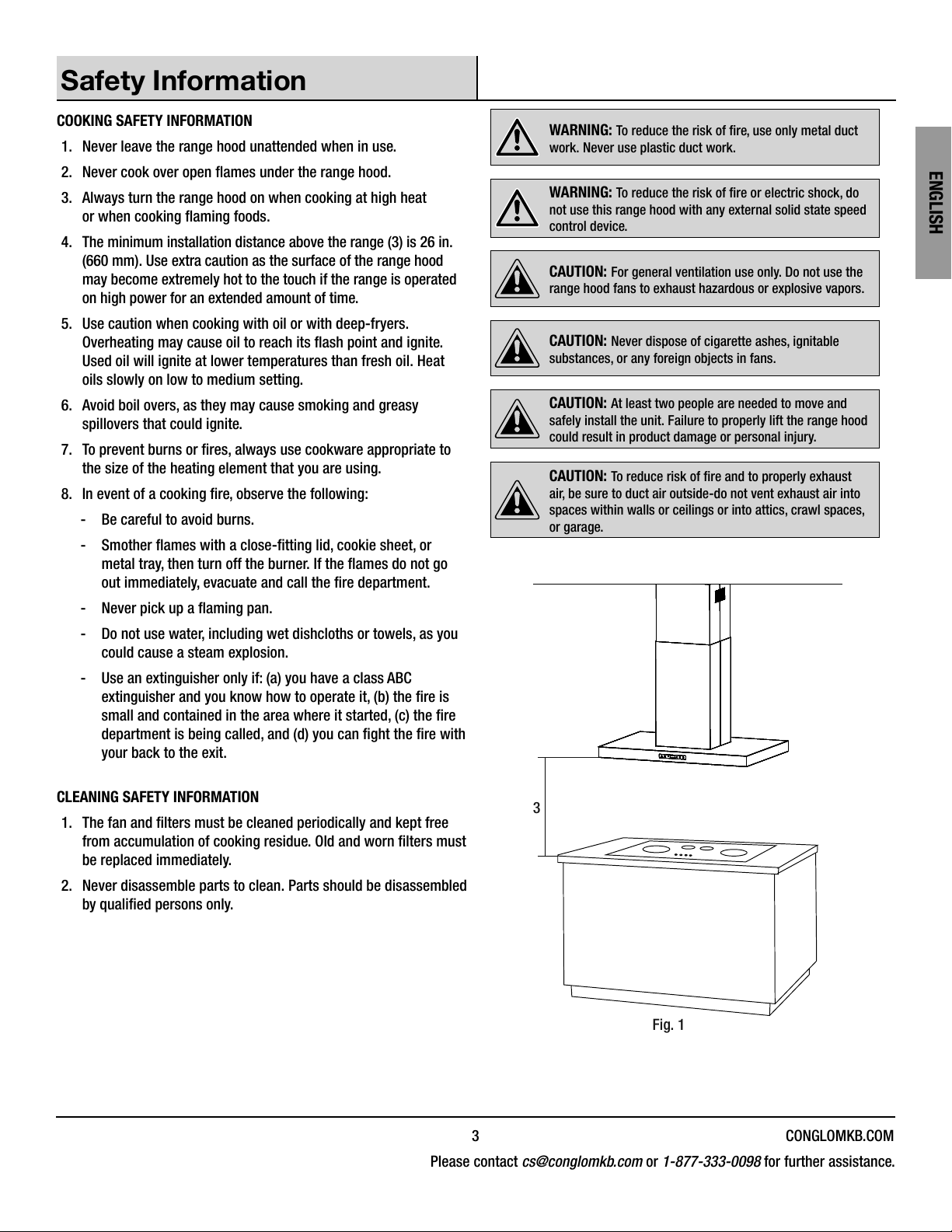
4. The minimum installation distance above the range (3) is 26 in.
(660 mm). Use extra caution as the surface of the range hood
may become extremely hot to the touch if the range is operated
on high power for an extended amount of time.
5. Use caution when cooking with oil or with deep-fryers.
Overheating may cause oil to reach its ash point and ignite.
Used oil will ignite at lower temperatures than fresh oil. Heat
oils slowly on low to medium setting.
6. Avoid boil overs, as they may cause smoking and greasy
spillovers that could ignite.
7. To prevent burns or res, always use cookware appropriate to
the size of the heating element that you are using.
8. In event of a cooking re, observe the following:
-Be careful to avoid burns.
- Smother ames with a close-tting lid, cookie sheet, or
metal tray, then turn off the burner. If the ames do not go
out immediately, evacuate and call the re department.
- Never pick up a aming pan.
-Do not use water, including wet dishcloths or towels, as you
could cause a steam explosion.
- Use an extinguisher only if: (a) you have a class ABC
extinguisher and you know how to operate it, (b) the re is
small and contained in the area where it started, (c) the re
department is being called, and (d) you can ght the re with
your back to the exit.
CLEANING SAFETY INFORMATION
1. The fan and lters must be cleaned periodically and kept free
from accumulation of cooking residue. Old and worn lters must
be replaced immediately.
2. Never disassemble parts to clean. Parts should be disassembled
by qualied persons only.
WARNING: To reduce the risk of re, use only metal duct
work. Never use plastic duct work.
WARNING: To reduce the risk of re or electric shock, do
not use this range hood with any external solid state speed
control device.
CAUTION: For general ventilation use only. Do not use the
range hood fans to exhaust hazardous or explosive vapors.
CAUTION: Never dispose of cigarette ashes, ignitable
substances, or any foreign objects in fans.
CAUTION: At least two people are needed to move and
safely install the unit. Failure to properly lift the range hood
could result in product damage or personal injury.
CAUTION: To reduce risk of re and to properly exhaust
air, be sure to duct air outside-do not vent exhaust air into
spaces within walls or ceilings or into attics, crawl spaces,
or garage.
3
Fig. 1
QR841 4
ENGLISH
Warranty
ONE YEAR LIMITED WARRANTY
A thorough inspection must be made before installation and any damage must be promptly reported. We will not be liable for failures or
damage that could have been discovered or avoided by proper inspection and testing prior to installation.
Conglom Inc. warrants this product to be free from defects in materials or workmanship for one (1) year from the date of purchase. Proof of
purchase (original sales receipt) from the original consumer purchaser must be made available to Conglom Inc. for all warranty claims.
This warranty is non-transferable and shall be voided if the unit is removed from its initial installation or if it is not installed following
the manufacturer’s instructions. It does not apply in the event of product damage due to the use of other than genuine Conglom Inc.
replacement parts, (Replacement parts may be obtained by e-mail at cs@conglomkb.com or by calling 1-877-333-0098 between
8:30 am - 5:00 pm EST) installation error, abuse, misuse or improper care and maintenance (whether performed by a plumber, contractor,
service provider or member of the purchaser’s household). The warranty excludes damage due to aggressive air or water conditions, harsh
or abrasive cleaners and/or materials.
Under no circumstance shall we be held liable for personal injury or property damage resulting from improper installation or use of this
product. We will not be held liable for inconvenience caused by loss of use of this product, costs incurred for labour or materials, removal
and installation of replacement units, or any other incidental or consequential damages. Costs relating to obtaining access for repair or
replacement are the responsibility of the user.
Our obligation shall be limited to the repair or replacement of a unit (at our discretion) that may prove, by our sole examination, to be defective
under normal use and service during the warranty period.
Any failure of this product that is not traceable to a defect in material or workmanship is not covered by this warranty. These non-warrantable
items include, but are not limited to:
-Improper installation not in accordance with manufacturer’s instructions.
-Dents and/or scratches incurred during shipping, handling, or installation.
- Change in colour or nish due to chemical usage.
-Damage caused by failure to follow care and cleaning guidelines, including damage caused by the use of abrasive cleaners.
-Alterations made to the unit by the purchaser or installer.
- Damage caused by accidental impact, re, ood, freezing, and normal wear.
- Bends and warping caused by forced connections, over-tightened ttings, and inadequate support during installation.
-Any defects or damage to light bulbs.
This warranty does not extend to commercial and institutional installation or use.
WARRANTY CLAIM PROCEDURE
If a claimable defect occurs or replacement parts are needed, please contact our customer service team at cs@conglomkb.com or
1-877-333-0098 (Service available in English and French, Monday - Friday from 8:30 am - 5 pm, EST).
Before you make your call, please ensure that you have:
-Model number or description.
-Proof of sale.
-Details regarding the defect and/or part number.
-Name(s) and address(es) of the owner and/or installer.
5 CONGLOMKB.COM
Please contact cs@conglomkb.com or 1-877-333-0098 for further assistance.
ENGLISH
Pre-Installation
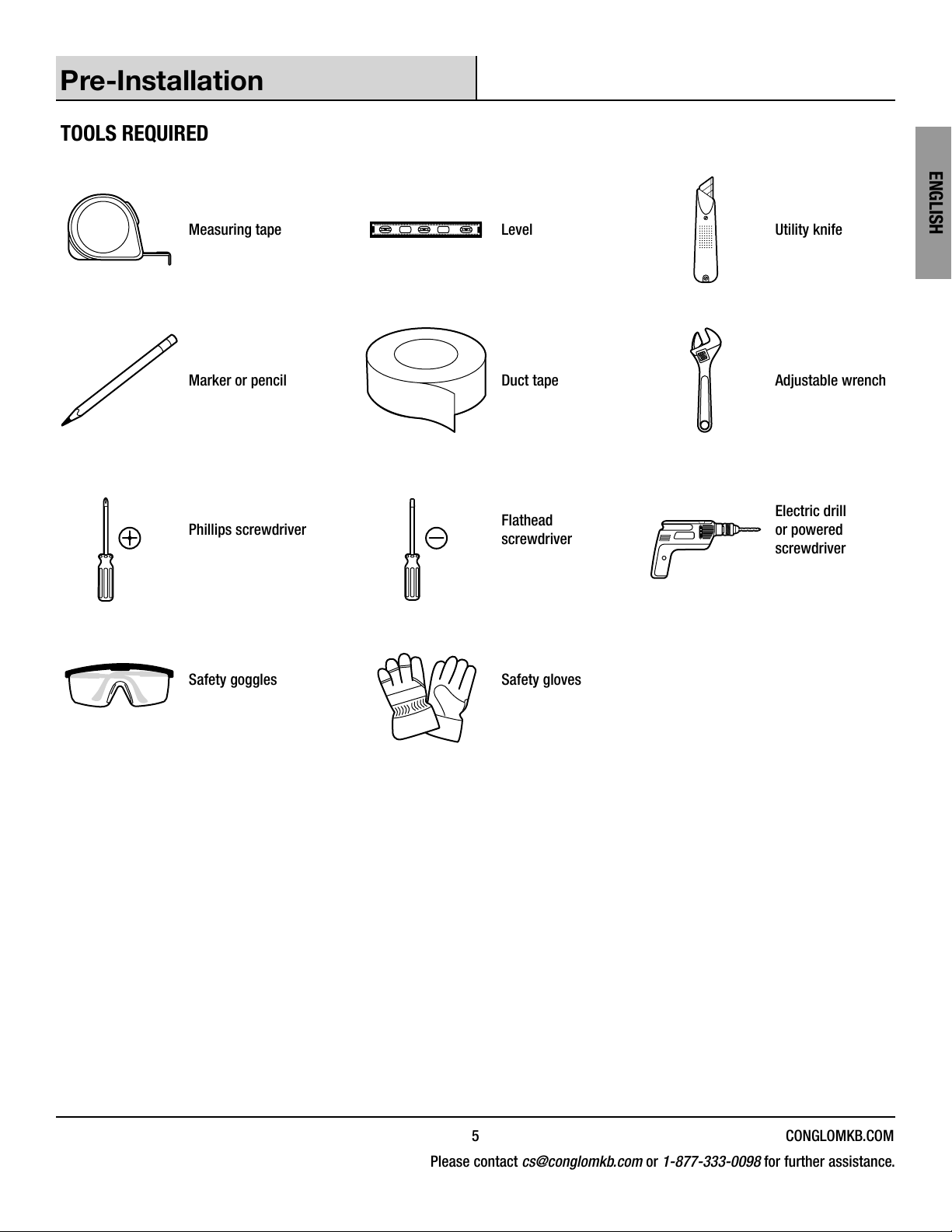
TOOLS REQUIRED
Measuring tape Level Utility knife
Marker or pencil Duct tape Adjustable wrench
Phillips screwdriver Flathead
screwdriver
Electric drill
or powered
screwdriver
Safety goggles Safety gloves
QR841 6
ENGLISH
Pre-Installation (continued)
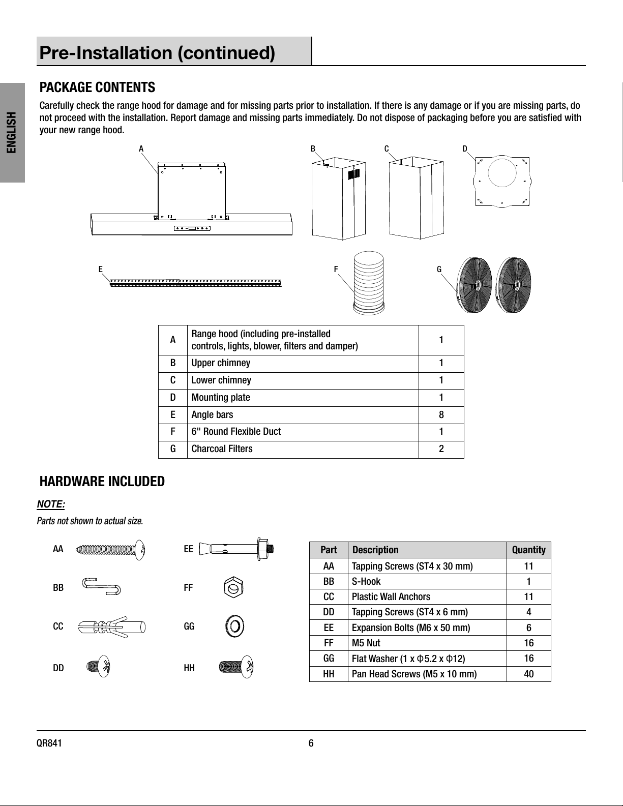
PACKAGE CONTENTS
Carefully check the range hood for damage and for missing parts prior to installation. If there is any damage or if you are missing parts, do
not proceed with the installation. Report damage and missing parts immediately. Do not dispose of packaging before you are satised with
your new range hood.
A B C D
EG
F
ARange hood (including pre-installed
controls, lights, blower, lters and damper) 1
B Upper chimney 1
C Lower chimney 1
D Mounting plate 1
E Angle bars 8
F6" Round Flexible Duct 1
G Charcoal Filters 2
HARDWARE INCLUDED
NOTE:
Parts not shown to actual size.
AA
BB
CC
DD
EE
FF
GG
HH
Part Description Quantity
AA Tapping Screws (ST4 x 30 mm) 11
BB S-Hook 1
CC Plastic Wall Anchors 11
DD Tapping Screws (ST4 x 6 mm) 4
EE Expansion Bolts (M6 x 50 mm) 6
FF M5 Nut 16
GG Flat Washer (1 x Φ5.2 x Φ12) 16
HH Pan Head Screws (M5 x 10 mm) 40
7 CONGLOMKB.COM
Please contact cs@conglomkb.com or 1-877-333-0098 for further assistance.
ENGLISH
Pre-Installation (continued)
PLANNING INSTALLATION
Number of people required: 2 strongly recommended.
1. Choose a location for your range hood. The range hood location
should be away from strong draft areas, such as windows,
doors, and strong heating vents.
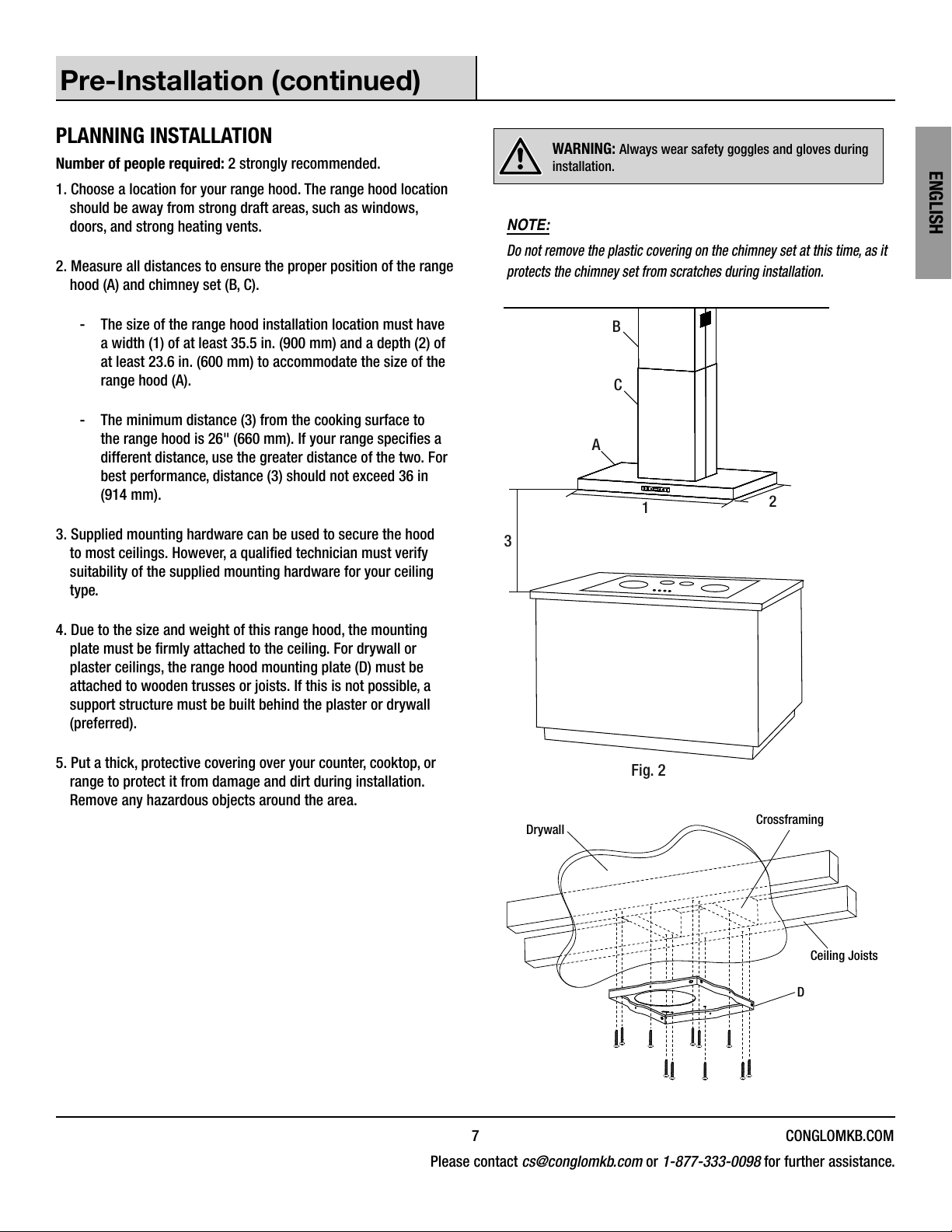
2. Measure all distances to ensure the proper position of the range
hood (A) and chimney set (B, C).
-The size of the range hood installation location must have
a width (1) of at least 35.5 in. (900 mm) and a depth (2) of
at least 23.6 in. (600 mm) to accommodate the size of the
range hood (A).
-The minimum distance (3) from the cooking surface to
the range hood is 26" (660 mm). If your range species a
different distance, use the greater distance of the two. For
best performance, distance (3) should not exceed 36 in
(914 mm).
3. Supplied mounting hardware can be used to secure the hood
to most ceilings. However, a qualied technician must verify
suitability of the supplied mounting hardware for your ceiling
type.
4. Due to the size and weight of this range hood, the mounting
plate must be rmly attached to the ceiling. For drywall or
plaster ceilings, the range hood mounting plate (D) must be
attached to wooden trusses or joists. If this is not possible, a
support structure must be built behind the plaster or drywall
(preferred).
5. Put a thick, protective covering over your counter, cooktop, or
range to protect it from damage and dirt during installation.
Remove any hazardous objects around the area.
WARNING: Always wear safety goggles and gloves during
installation.
NOTE:
Do not remove the plastic covering on the chimney set at this time, as it
protects the chimney set from scratches during installation.
3
B
C
A
12
Fig. 2
D
Drywall Crossframing
Ceiling Joists
QR841 8
ENGLISH
Pre-Installation (continued)
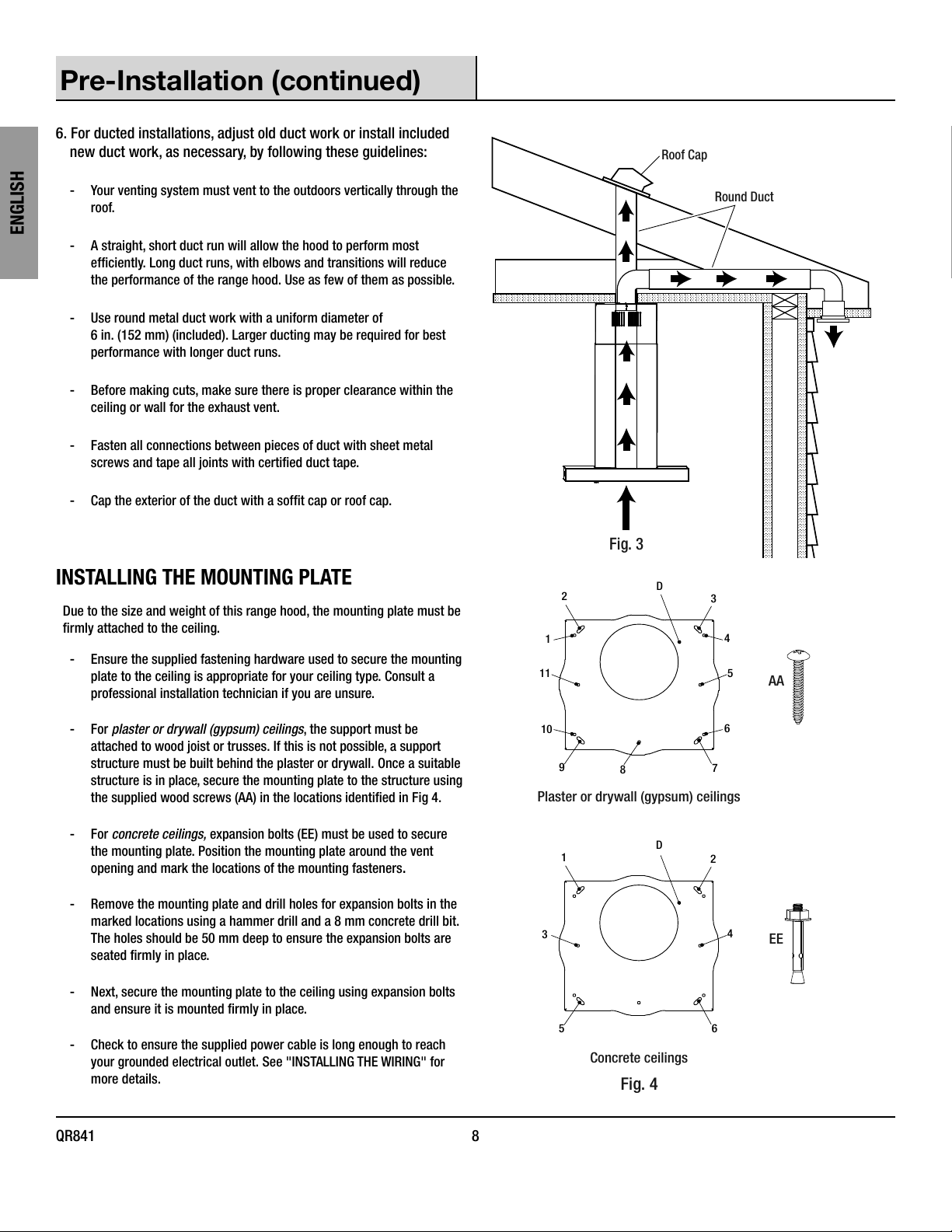
6. For ducted installations, adjust old duct work or install included
new duct work, as necessary, by following these guidelines:
-Your venting system must vent to the outdoors vertically through the
roof.
-A straight, short duct run will allow the hood to perform most
efciently. Long duct runs, with elbows and transitions will reduce
the performance of the range hood. Use as few of them as possible.
-Use round metal duct work with a uniform diameter of
6 in. (152 mm) (included). Larger ducting may be required for best
performance with longer duct runs.
-Before making cuts, make sure there is proper clearance within the
ceiling or wall for the exhaust vent.
-Fasten all connections between pieces of duct with sheet metal
screws and tape all joints with certied duct tape.
- Cap the exterior of the duct with a soft cap or roof cap.
Fig. 3
Roof Cap
Round Duct
INSTALLING THE MOUNTING PLATE
Due to the size and weight of this range hood, the mounting plate must be
rmly attached to the ceiling.
-Ensure the supplied fastening hardware used to secure the mounting
plate to the ceiling is appropriate for your ceiling type. Consult a
professional installation technician if you are unsure.
-For plaster or drywall (gypsum) ceilings, the support must be
attached to wood joist or trusses. If this is not possible, a support
structure must be built behind the plaster or drywall. Once a suitable
structure is in place, secure the mounting plate to the structure using
the supplied wood screws (AA) in the locations identied in Fig 4.
-For concrete ceilings, expansion bolts (EE) must be used to secure
the mounting plate. Position the mounting plate around the vent
opening and mark the locations of the mounting fasteners.
- Remove the mounting plate and drill holes for expansion bolts in the
marked locations using a hammer drill and a 8 mm concrete drill bit.
The holes should be 50 mm deep to ensure the expansion bolts are
seated rmly in place.
- Next, secure the mounting plate to the ceiling using expansion bolts
and ensure it is mounted rmly in place.
-Check to ensure the supplied power cable is long enough to reach
your grounded electrical outlet. See "INSTALLING THE WIRING" for
more details.
Fig. 4
Plaster or drywall (gypsum) ceilings
D
Concrete ceilings
AA
EE
1
23
4
5
6
7
8
9
10
11
D
12
4
6
5
3
9 CONGLOMKB.COM
Please contact cs@conglomkb.com or 1-877-333-0098 for further assistance.
ENGLISH
Installation
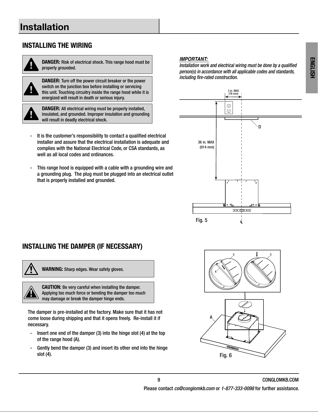
INSTALLING THE WIRING
DANGER: Risk of electrical shock. This range hood must be
properly grounded.
DANGER: Turn off the power circuit breaker or the power
switch on the junction box before installing or servicing
this unit. Touching circuitry inside the range hood while it is
energized will result in death or serious injury.
DANGER: All electrical wiring must be properly installed,
insulated, and grounded. Improper insulation and grounding
will result in deadly electrical shock.
- It is the customer’s responsibility to contact a qualied electrical
installer and assure that the electrical installation is adequate and
complies with the National Electrical Code, or CSA standards, as
well as all local codes and ordinances.
-This range hood is equipped with a cable with a grounding wire and
a grounding plug. The plug must be plugged into an electrical outlet
that is properly installed and grounded.
IMPORTANT:
Installation work and electrical wiring must be done by a qualied
person(s) in accordance with all applicable codes and standards,
including re-rated construction.
3 in. MAX
(76 mm)
36 in. MAX
(914 mm)
Fig. 5
D
C
L
INSTALLING THE DAMPER (IF NECESSARY)
WARNING: Sharp edges. Wear safety gloves.
CAUTION: Be very careful when installing the damper.
Applying too much force or bending the damper too much
may damage or break the damper hinge ends.
The damper is pre-installed at the factory. Make sure that it has not
come loose during shipping and that it opens freely. Re-install it if
necessary.
-Insert one end of the damper (3) into the hinge slot (4) at the top
of the range hood (A).
-Gently bend the damper (3) and insert its other end into the hinge
slot (4).
A
3
4
3
Fig. 6
QR841 10
ENGLISH
Installation (continued)
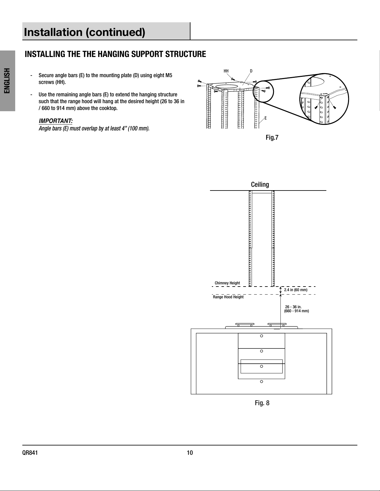
INSTALLING THE THE HANGING SUPPORT STRUCTURE
-Secure angle bars (E) to the mounting plate (D) using eight M5
screws (HH).
- Use the remaining angle bars (E) to extend the hanging structure
such that the range hood will hang at the desired height (26 to 36 in
/ 660 to 914 mm) above the cooktop.
IMPORTANT:
Angle bars (E) must overlap by at least 4” (100 mm).
HH D
E
Fig.7
Ceiling
26 - 36 in.
(660 - 914 mm)
2.4 in (60 mm)
Chimney Height
Range Hood Height
Fig. 8
11 CONGLOMKB.COM
Please contact cs@conglomkb.com or 1-877-333-0098 for further assistance.
ENGLISH
Installation (continued)
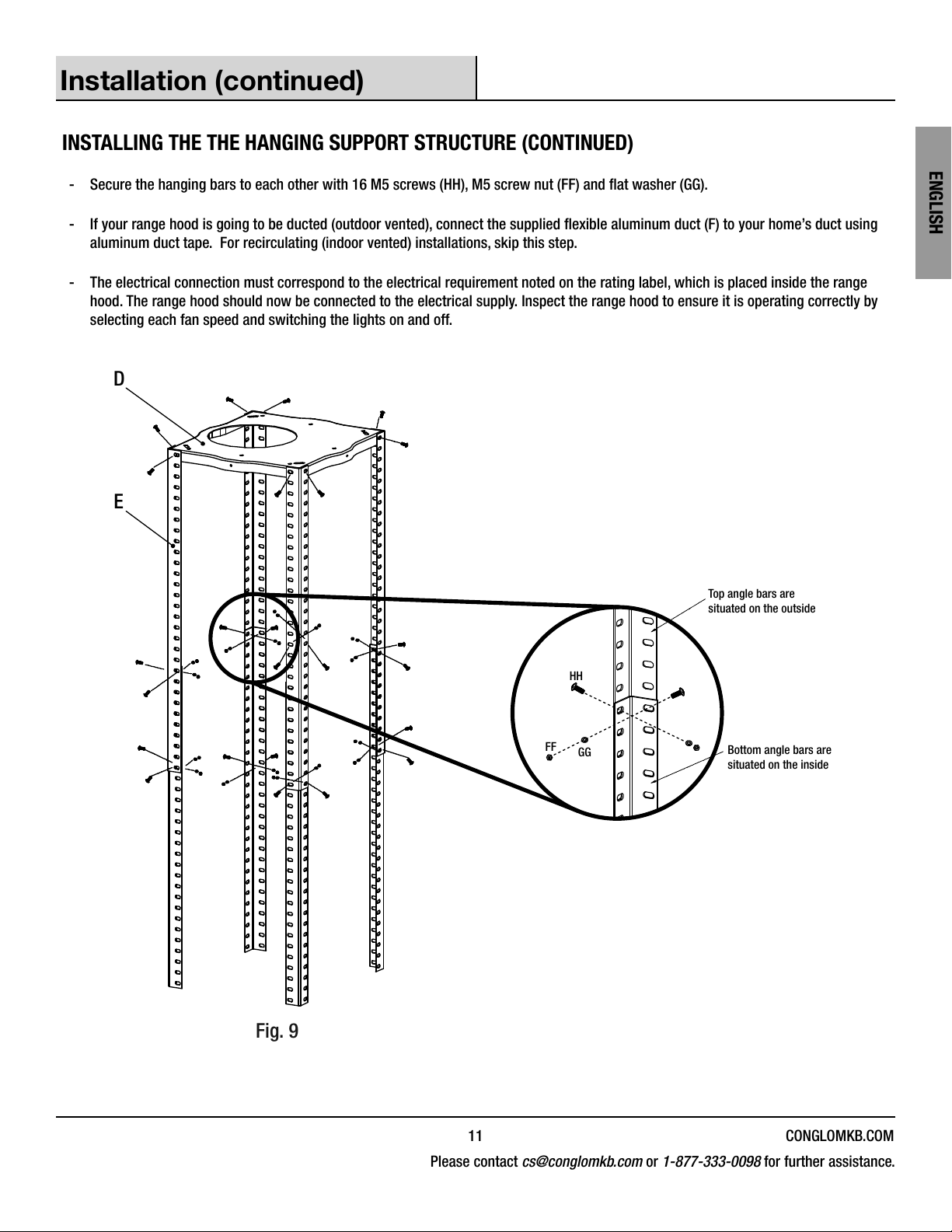
INSTALLING THE THE HANGING SUPPORT STRUCTURE (CONTINUED)
- Secure the hanging bars to each other with 16 M5 screws (HH), M5 screw nut (FF) and at washer (GG).
- If your range hood is going to be ducted (outdoor vented), connect the supplied exible aluminum duct (F) to your home’s duct using
aluminum duct tape. For recirculating (indoor vented) installations, skip this step.
-The electrical connection must correspond to the electrical requirement noted on the rating label, which is placed inside the range
hood. The range hood should now be connected to the electrical supply. Inspect the range hood to ensure it is operating correctly by
selecting each fan speed and switching the lights on and off.
D
E
Fig. 9
HH
Bottom angle bars are
situated on the inside
Top angle bars are
situated on the outside
FF GG
QR841 12
ENGLISH
Installation (continued)
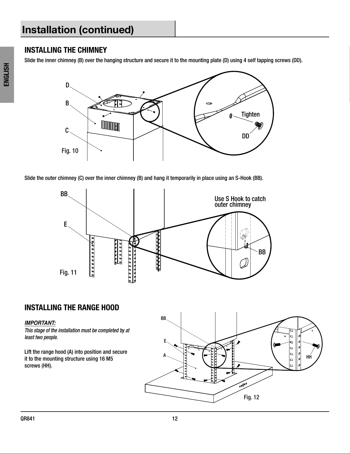
INSTALLING THE CHIMNEY
Slide the inner chimney (B) over the hanging structure and secure it to the mounting plate (D) using 4 self tapping screws (DD).
D
B
C
Tighten
DD
Fig. 10
Slide the outer chimney (C) over the inner chimney (B) and hang it temporarily in place using an S-Hook (BB).
BB
E
Use S Hook to catch
outer chimney
Fig. 11
BB
INSTALLING THE RANGE HOOD
IMPORTANT:
This stage of the installation must be completed by at
least two people.
Lift the range hood (A) into position and secure
it to the mounting structure using 16 M5
screws (HH).
E
BB
AHH
Fig. 12
13 CONGLOMKB.COM
Please contact cs@conglomkb.com or 1-877-333-0098 for further assistance.
ENGLISH
Installation (continued)
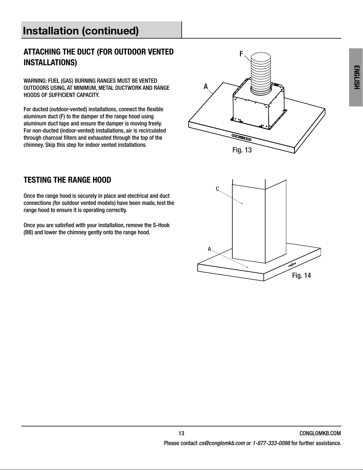
ATTACHING THE DUCT (FOR OUTDOOR VENTED
INSTALLATIONS)
WARNING: FUEL (GAS) BURNING RANGES MUST BE VENTED
OUTDOORS USING, AT MINIMUM, METAL DUCTWORK AND RANGE
HOODS OF SUFFICIENT CAPACITY.
For ducted (outdoor-vented) installations, connect the exible
aluminum duct (F) to the damper of the range hood using
aluminum duct tape and ensure the damper is moving freely.
For non-ducted (indoor-vented) installations, air is recirculated
through charcoal lters and exhausted through the top of the
chimney. Skip this step for indoor vented installations. Fig. 13
A
F
TESTING THE RANGE HOOD
Once the range hood is securely in place and electrical and duct
connections (for outdoor vented models) have been made, test the
range hood to ensure it is operating correctly.
Once you are satised with your installation, remove the S-Hook
(BB) and lower the chimney gently onto the range hood.
C
A
Fig. 14
QR841 14
ENGLISH
Operation
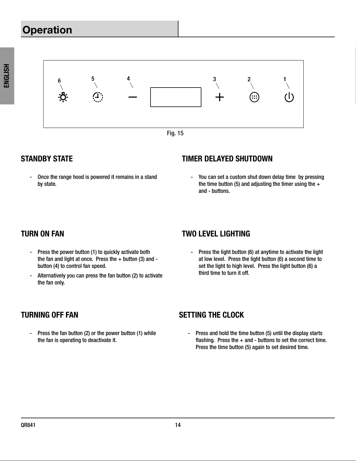
Fig. 15
STANDBY STATE
-Once the range hood is powered it remains in a stand
by state.
TIMER DELAYED SHUTDOWN
-You can set a custom shut down delay time by pressing
the time button (5) and adjusting the timer using the +
and - buttons.
TURN ON FAN
-Press the power button (1) to quickly activate both
the fan and light at once. Press the + button (3) and -
button (4) to control fan speed.
-Alternatively you can press the fan button (2) to activate
the fan only.
TWO LEVEL LIGHTING
-Press the light button (6) at anytime to activate the light
at low level. Press the light button (6) a second time to
set the light to high level. Press the light button (6) a
third time to turn it off.
TURNING OFF FAN
-Press the fan button (2) or the power button (1) while
the fan is operating to deactivate it.
SETTING THE CLOCK
-Press and hold the time button (5) until the display starts
ashing. Press the + and - buttons to set the correct time.
Press the time button (5) again to set desired time.
15 CONGLOMKB.COM
Please contact cs@conglomkb.com or 1-877-333-0098 for further assistance.
ENGLISH
Maintenance
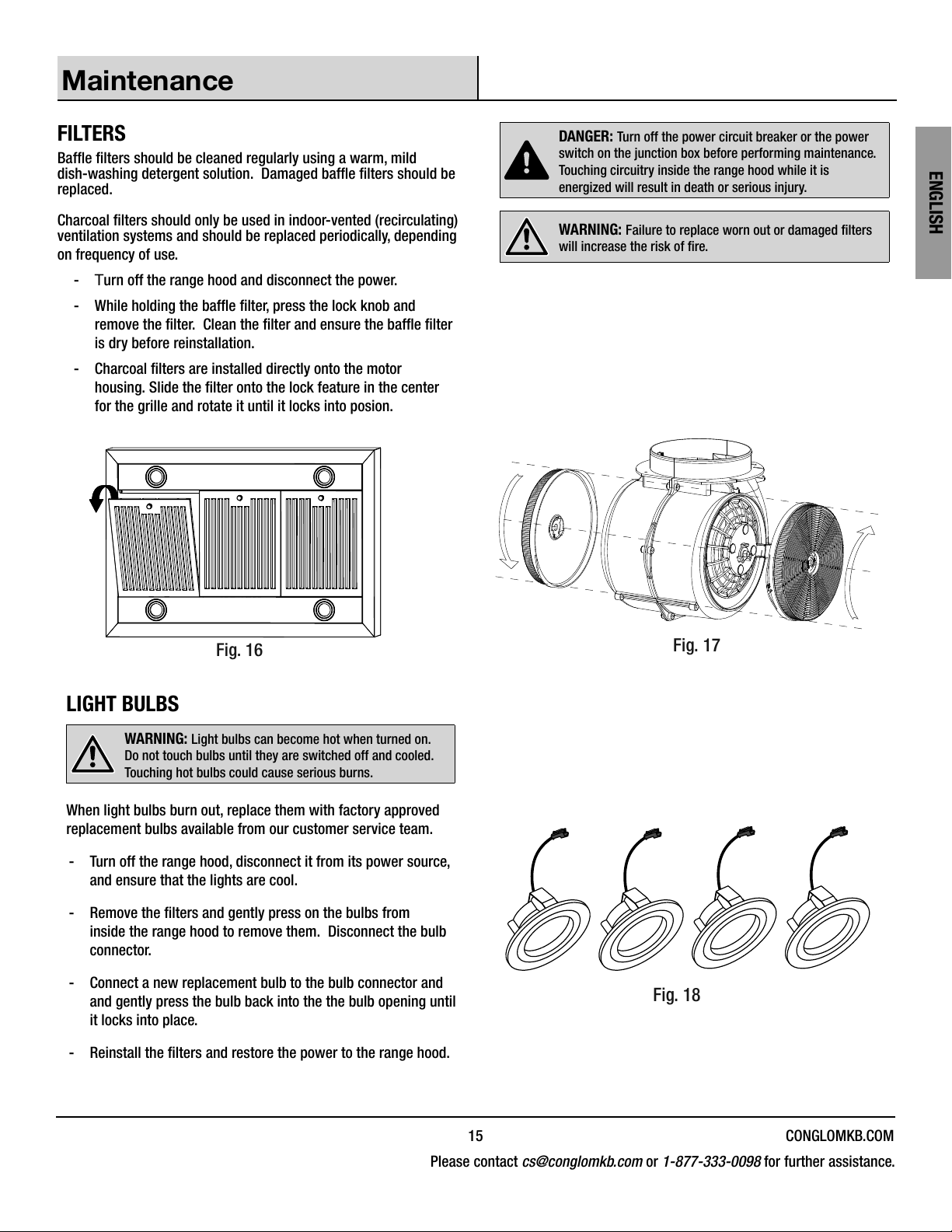
FILTERS
Bafe lters should be cleaned regularly using a warm, mild
dish-washing detergent solution. Damaged bafe lters should be
replaced.
Charcoal lters should only be used in indoor-vented (recirculating)
ventilation systems and should be replaced periodically, depending
on frequency of use.
-Turn off the range hood and disconnect the power.
- While holding the bafe lter, press the lock knob and
remove the lter. Clean the lter and ensure the bafe lter
is dry before reinstallation.
- Charcoal lters are installed directly onto the motor
housing. Slide the lter onto the lock feature in the center
for the grille and rotate it until it locks into posion.
Fig. 16
DANGER: Turn off the power circuit breaker or the power
switch on the junction box before performing maintenance.
Touching circuitry inside the range hood while it is
energized will result in death or serious injury.
WARNING: Failure to replace worn out or damaged lters
will increase the risk of re.
Fig. 17
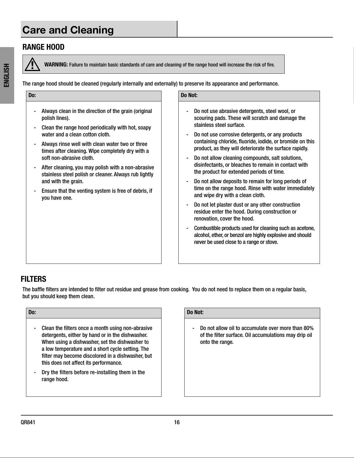
LIGHT BULBS
WARNING: Light bulbs can become hot when turned on.
Do not touch bulbs until they are switched off and cooled.
Touching hot bulbs could cause serious burns.
When light bulbs burn out, replace them with factory approved
replacement bulbs available from our customer service team.
-Turn off the range hood, disconnect it from its power source,
and ensure that the lights are cool.
- Remove the lters and gently press on the bulbs from
inside the range hood to remove them. Disconnect the bulb
connector.
-Connect a new replacement bulb to the bulb connector and
and gently press the bulb back into the the bulb opening until
it locks into place.
- Reinstall the lters and restore the power to the range hood.
Fig. 18
QR841 16
ENGLISH
Care and Cleaning
RANGE HOOD
WARNING: Failure to maintain basic standards of care and cleaning of the range hood will increase the risk of re.
The range hood should be cleaned (regularly internally and externally) to preserve its appearance and performance.
Do: Do Not:
-Always clean in the direction of the grain (original
polish lines).
-Clean the range hood periodically with hot, soapy
water and a clean cotton cloth.
-Always rinse well with clean water two or three
times after cleaning. Wipe completely dry with a
soft non-abrasive cloth.
- After cleaning, you may polish with a non-abrasive
stainless steel polish or cleaner. Always rub lightly
and with the grain.
-Ensure that the venting system is free of debris, if
you have one.
-Do not use abrasive detergents, steel wool, or
scouring pads. These will scratch and damage the
stainless steel surface.
-Do not use corrosive detergents, or any products
containing chloride, uoride, iodide, or bromide on this
product, as they will deteriorate the surface rapidly.
-Do not allow cleaning compounds, salt solutions,
disinfectants, or bleaches to remain in contact with
the product for extended periods of time.
-Do not allow deposits to remain for long periods of
time on the range hood. Rinse with water immediately
and wipe dry with a clean cloth.
-Do not let plaster dust or any other construction
residue enter the hood. During construction or
renovation, cover the hood.
-Combustible products used for cleaning such as acetone,
alcohol, ether, or benzol are highly explosive and should
never be used close to a range or stove.
FILTERS
The bafe lters are intended to lter out residue and grease from cooking. You do not need to replace them on a regular basis,
but you should keep them clean.
Do: Do Not:
- Clean the lters once a month using non-abrasive
detergents, either by hand or in the dishwasher.
When using a dishwasher, set the dishwasher to
a low temperature and a short cycle setting. The
lter may become discolored in a dishwasher, but
this does not affect its performance.
-Dry the lters before re-installing them in the
range hood.
-Do not allow oil to accumulate over more than 80%
of the lter surface. Oil accumulations may drip oil
onto the range.
17 CONGLOMKB.COM
Please contact cs@conglomkb.com or 1-877-333-0098 for further assistance.
ENGLISH
Troubleshooting
DANGER: Turn off the power circuit breaker or the power switch on the junction box before performing maintenance. Touching circuitry inside
the range hood while it is energized will result in death or serious injury.
Problem Solution
The range hood will not operate. -Check that the power supply cable and all electrical wiring are properly
connected.
- Check that the power is turned on at the junction box or circuit breaker.
-Check that the wiring between the switch control and the control board are
connected properly.
The range hood vibrates when the fan is operating. -Check that the range hood has been secured properly to the wall. Tighten into
position, if necessary.
-Check that the motor is secured in place. If not, then tighten the motor in place.
-Check that the fan is not damaged. If so, replace the fan.
The fans seem weak. -Check that the duct size used is at least 6 in. (152 mm) round. The range hood
will not function efciently with insufcient duct size.
-Check that the duct is not clogged with debris and the tight mesh on the wall
cap, if applicable, isn’t restricting air ow.
-Check that the damper unit is opening properly.
-Check that no birds or animals have nested in the duct.
The lights work, but the fan is not spinning, is stuck,
or is rattling. -The thermal protection system detects if the motor is too hot to operate and
shuts the motor down. In this case, the motor will function properly after the
thermal protection system cools down (after approximately 10 min.).
-Check that the fan isn’t jammed.
-If nothing else works, the motor may be defective or seized. If so, replace the
motor.
The range hood is not venting properly. -Check that no birds or animals have nested in the duct.
-Check that the distance between the cooktop and the bottom of the range hood
is within the previously recommended distance.
-Check that duct work follows all requirements. Use round metal duct work with
a uniform diameter of 6 in. (152 mm). The length of duct work must not exceed
35 ft (10.7 m). Reduce the length of duct work and the number of elbows if
necessary. Ensure that all joints are properly connected, sealed, and taped.
-Check that the duct does not open against the wind.
-Ensure that the power is on high speed for heavy cooking.
-Wind from opened windows or doors may affect the performance of the range
hood. Close all windows and doors to eliminate outside air ow.
-To enhance the performance of the range hood, open slightly a window on the
opposite side of the house where the range hood vents outdoors.
The light does not work. -Check to see if light bulb is burnt. If so, replace.
-Check to ensure the light bulb is connected properly.
QR841 18
ENGLISH
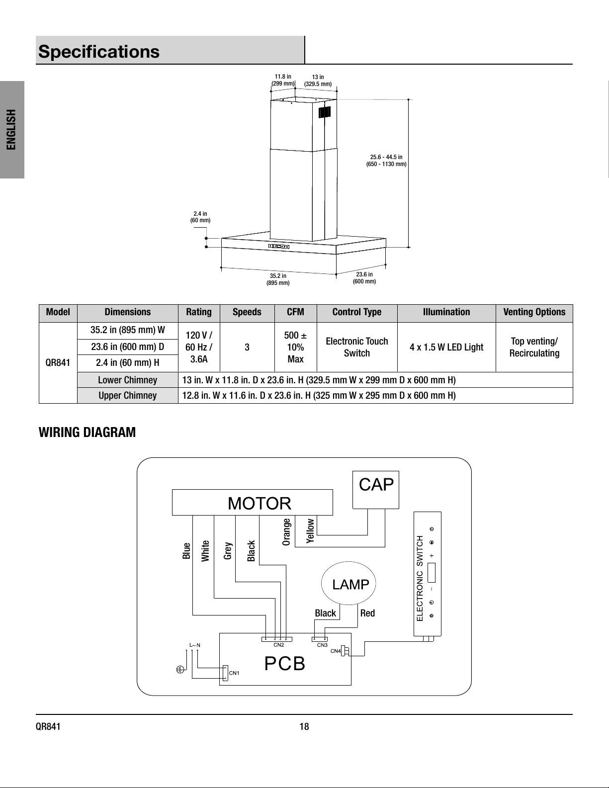
Specications
11.8 in
(299 mm)
13 in
(329.5 mm)
2.4 in
(60 mm)
35.2 in
(895 mm)
23.6 in
(600 mm)
25.6 - 44.5 in
(650 - 1130 mm)
Model Dimensions Rating Speeds CFM Control Type Illumination Venting Options
QR841
35.2 in (895 mm) W 120 V /
60 Hz /
3.6A
3
500 ±
10%
Max
Electronic Touch
Switch 4 x 1.5 W LED Light Top venting/
Recirculating
23.6 in (600 mm) D
2.4 in (60 mm) H
Lower Chimney 13 in. W x 11.8 in. D x 23.6 in. H (329.5 mm W x 299 mm D x 600 mm H)
Upper Chimney 12.8 in. W x 11.6 in. D x 23.6 in. H (325 mm W x 295 mm D x 600 mm H)
WIRING DIAGRAM
PCB
Yellow
Orange
Black
Grey
White
Blue
Black Red
19 CONGLOMKB.COM
Please contact cs@conglomkb.com or 1-877-333-0098 for further assistance.
ENGLISH
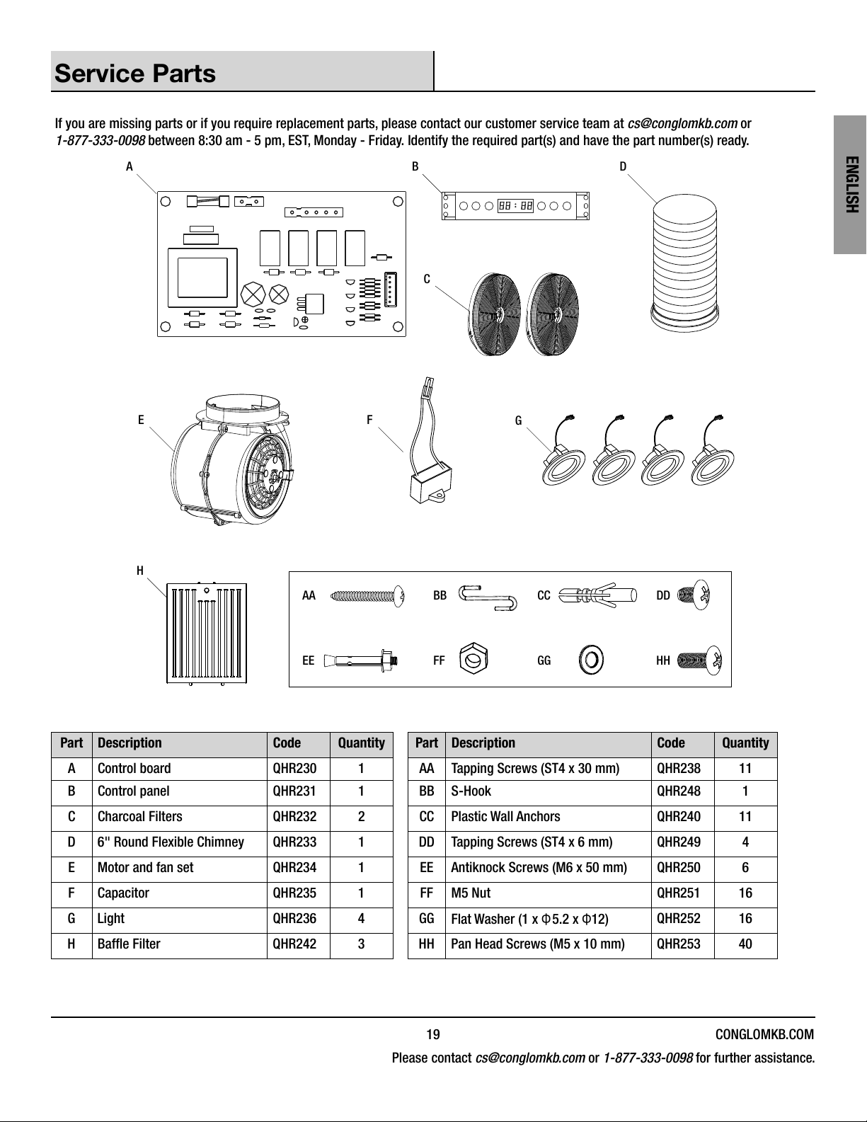
Service Parts
If you are missing parts or if you require replacement parts, please contact our customer service team at cs@conglomkb.com or
1-877-333-0098 between 8:30 am - 5 pm, EST, Monday - Friday. Identify the required part(s) and have the part number(s) ready.
EFG
A B
H
C
D
AA BB CC DD
EE FF GG HH
Part Description Code Quantity Part Description Code Quantity
A Control board QHR230 1 AA Tapping Screws (ST4 x 30 mm) QHR238 11
B Control panel QHR231 1 BB S-Hook QHR248 1
C Charcoal Filters QHR232 2 CC Plastic Wall Anchors QHR240 11
D6" Round Flexible Chimney QHR233 1 DD Tapping Screws (ST4 x 6 mm) QHR249 4
E Motor and fan set QHR234 1 EE Antiknock Screws (M6 x 50 mm) QHR250 6
F Capacitor QHR235 1 FF M5 Nut QHR251 16
G Light QHR236 4 GG Flat Washer (1 x Φ5.2 x Φ12) QHR252 16
HBafe Filter QHR242 3 HH Pan Head Screws (M5 x 10 mm) QHR253 40
FRANÇAIS
QR841 20
Table des matières
OWNER’S MANUAL ..................................2
Consignes de sécurité ..............................20
Garantie............................................
Garantie limitée d’un an............................22
Procédure de réclamation pour la garantie .............22
Préinstallation.......................................
Outils requis.....................................23
Contenu de l’emballage............................24
Quincaillerie incluse ..............................24
Planication de l’installation ........................25
Installation .......................................27
Fonctionnement ...................................32
Entretien ...........................................
Remplacement des ltres ..........................33
Remplacement des ampoules .......................33
Soin et nettoyage ....................................
Hotte de cuisinière................................34
Filtres..........................................34
Dépannage .......................................35
Caractéristiques .....................................
Schéma électrique................................36
Pièces de rechange ................................37
MANUAL DEL USARIO ...............................38
Consignes de sécurité
LIRE ET CONSERVER CES DIRECTIVES
Avertissement – An de réduire les risques d’incendie, de choc
électrique ou de blessures, veuillez prendre connaissance des
directives suivantes:
1. Cet appareil ne peut être utilisé autrement que pour l’usage
prévu par le fabricant. Consulter le fabricant pour toutes
questions concernant l’appareil.
2. Avant de réparer ou de nettoyer l’appareil, couper l’alimentation
électrique au panneau de service et le verrouiller pour éviter
toute remise en marche accidentelle. Si vous ne pouvez
verrouiller le panneau, y apposer un avertissement bien en vue.
3. L’installation et le raccordement électrique doivent être faits par
une(des) personne(s) qualiée(s), conformément aux codes et
normes de construction, incluant ceux concernant les incendies.
4. Un apport d’air sufsant est requis pour assurer une
combustion efcace et l’évacuation des gaz pour tous les
appareils de cuisson alimentés par un combustible an d’éviter
tout refoulement d’air. Suivre les directives et les normes de
sécurité du fabricant des appareils et se conformer aux normes
recommandées par The National Fire Protection Association
(NFPA), par l’American Society for Heating, Refrigeration and Air
Conditioning Engineers (ASHRAE), et par les autorités locales.
5. Lorsque vous faites une ouverture dans un mur ou un plafond,
veillez à ne pas endommager les ls électriques ou les
conduites qui y sont dissimulées.
6. Les ventilateurs à conduit doivent toujours être ventilés à
l’extérieur.
AVERTISSEMENT : L’ÉVACUATION DES GAZ D’UN APPAREIL DE
CUISSON ALIMENTÉ PAR UN COMBUSTIBLE (GAZ) DOIT ÊTRE
FAITE VERS L’EXTÉRIEUR EN UTILISANT AU MOINS UN CONDUIT
MÉTALLIQUE ET UNE HOTTE D’UNE CAPACITÉ SUFFISANTE. Respectez
les directives du fabricant de votre appareil de cuisson, de même
que toutes les normes de sécurité applicables publiées par la
National Fire Protection Association (NFPA) et l’American Society for
Heating, Refrigeration and Air Conditioning Engineers (ASHRAE), ainsi
que les codes du bâtiment locaux.
DANGER : Éteignez le disjoncteur électrique ou
l’interrupteur d’alimentation sur la boîte de jonction avant
d’installer ou de réparer cet appareil. Toucher un circuit
intérieur de la hotte alors qu’il est sous tension peut
entraîner des blessures graves, voire mortelles.
DANGER : Tout raccordement électrique doit être fait
conformément aux normes, isolé et mis à la terre. L’isolation
et la mise à la terre incorrectes entraîneront une décharge
électrique mortelle.
DANGER : Pour l’installation au-dessus d’une cuisinière
à gaz, le gaz doit être coupé à la source avant l’installation
ou l’entretien.
AVERTISSEMENT : Tenter d’installer ou de réparer
cet appareil lorsque vous n’avez pas les connaissances
techniques ou électriques nécessaires pourrait entraîner
des blessures.
AVERTISSEMENT : Les bordures de métal de l’appareil
peuvent être tranchantes. Veuillez porter des gants
protecteurs pendant l’installation, la nettoyage, ou la
réparation.
AVERTISSEMENT : Ne faites pas fonctionner l’appareil
sans les grilles de sécurité et les ltres, car sans ces
éléments, les ventilateurs pourraient aspirer la chevelure,
les doigts ou les vêtements amples.
AVERTISSEMENT : Restez à l’écart du ventilateur lorsque
le moteur est en marche.
AVERTISSEMENT : Gardez cet appareil propre et exempt
de graisse et d’accumulation de résidus en tout temps pour
prévenir les incendies.
PRUDENCE : Cet appareil est destiné à un usage de
ventilation de type générale seulement. Ne pas utiliser
pour évacuer des matières ou vapeurs dangereuses et
explosives.
Table of contents
Languages:
Other Aria Ventilation Hood manuals


Popular Ventilation Hood manuals by other brands

Caple
Caple CC400WH instruction manual

ROBLIN
ROBLIN Actis 3 Electro 5741 Instructions for use and installation

Franke
Franke FGL 9015 XS Instructions for use and installation

ROBLIN
ROBLIN INSPIRATION SLIM INOX Notice

Broan
Broan Best AEWPD29 installation instructions

Hotpoint
Hotpoint BH11 User handbook for installation and operation

Amica
Amica HCK624B instruction manual

Kernau
Kernau KBH 07601 X Manual instruction

NuTone
NuTone AVDN1 SERIES Installation use and care manual

Hanseatic
Hanseatic SY-6002C-P3-C84-L32-600 user manual

KitchenAid
KitchenAid KVWB400DSS0 Installation Instructions and Use & Care Guide

AEG
AEG DBE6980HM installation manual


