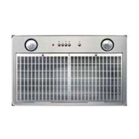
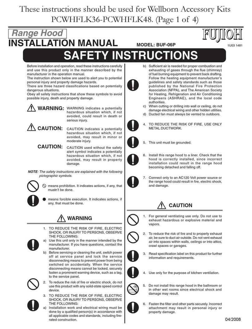
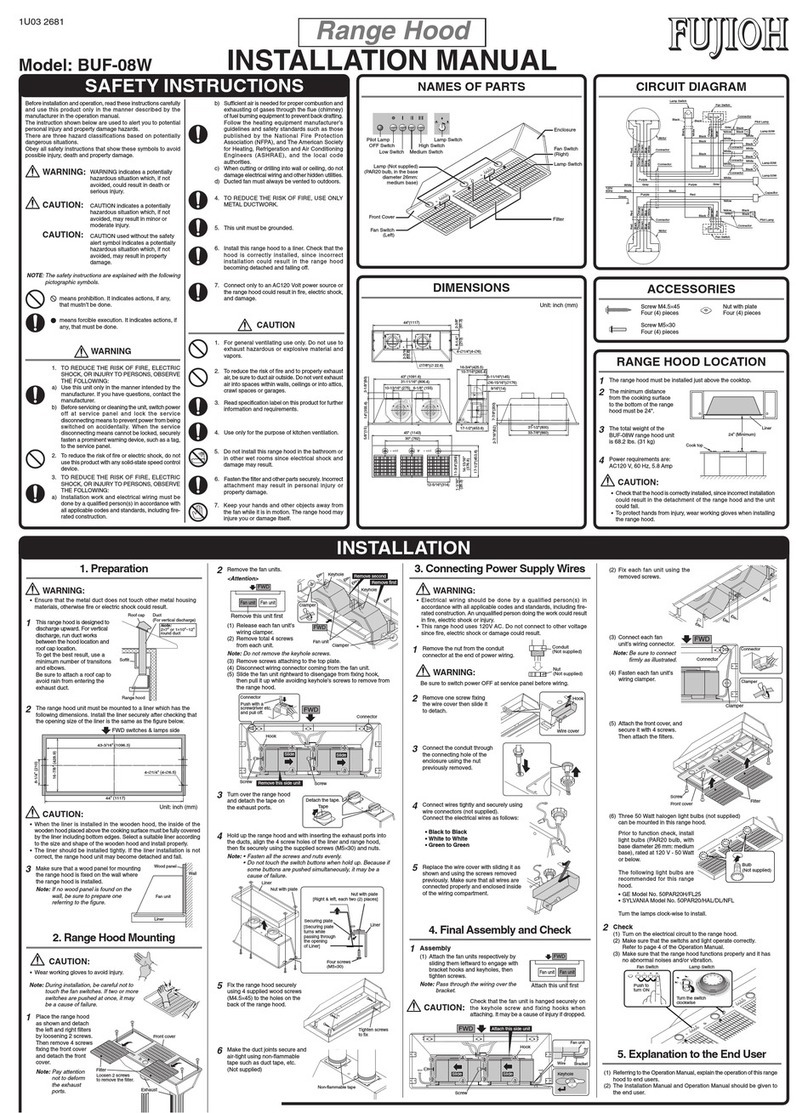
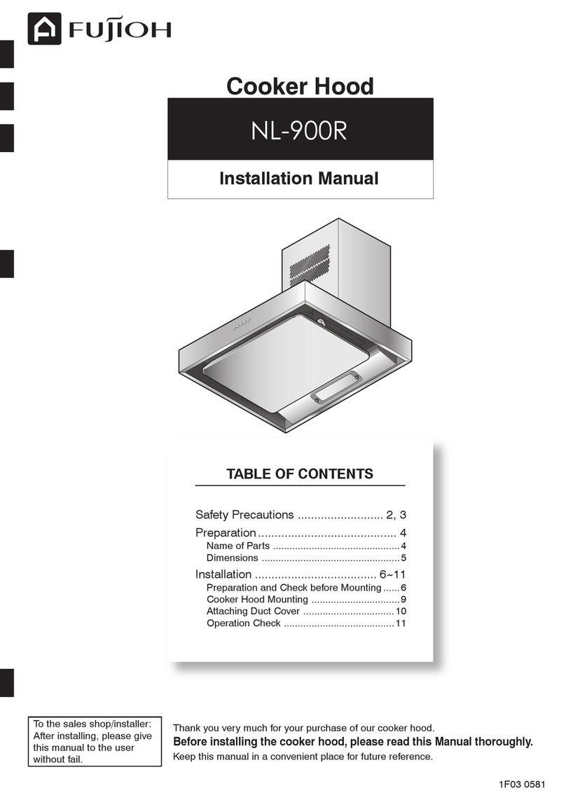
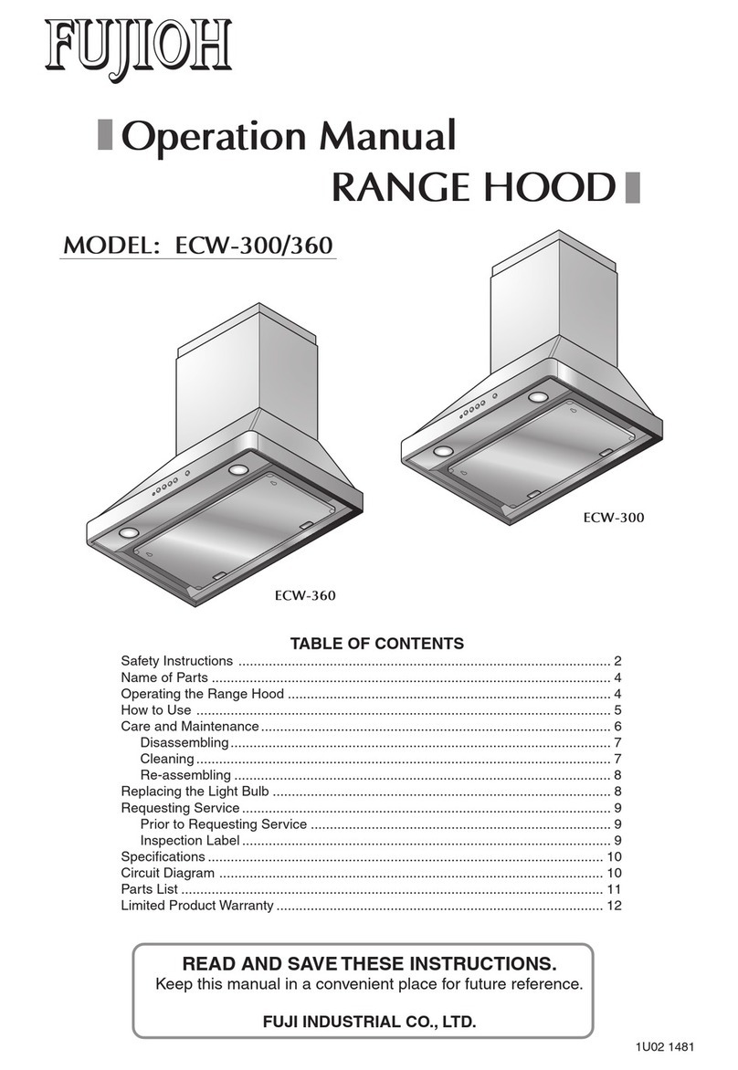
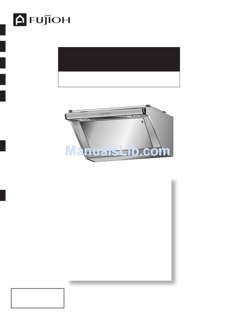
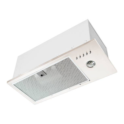
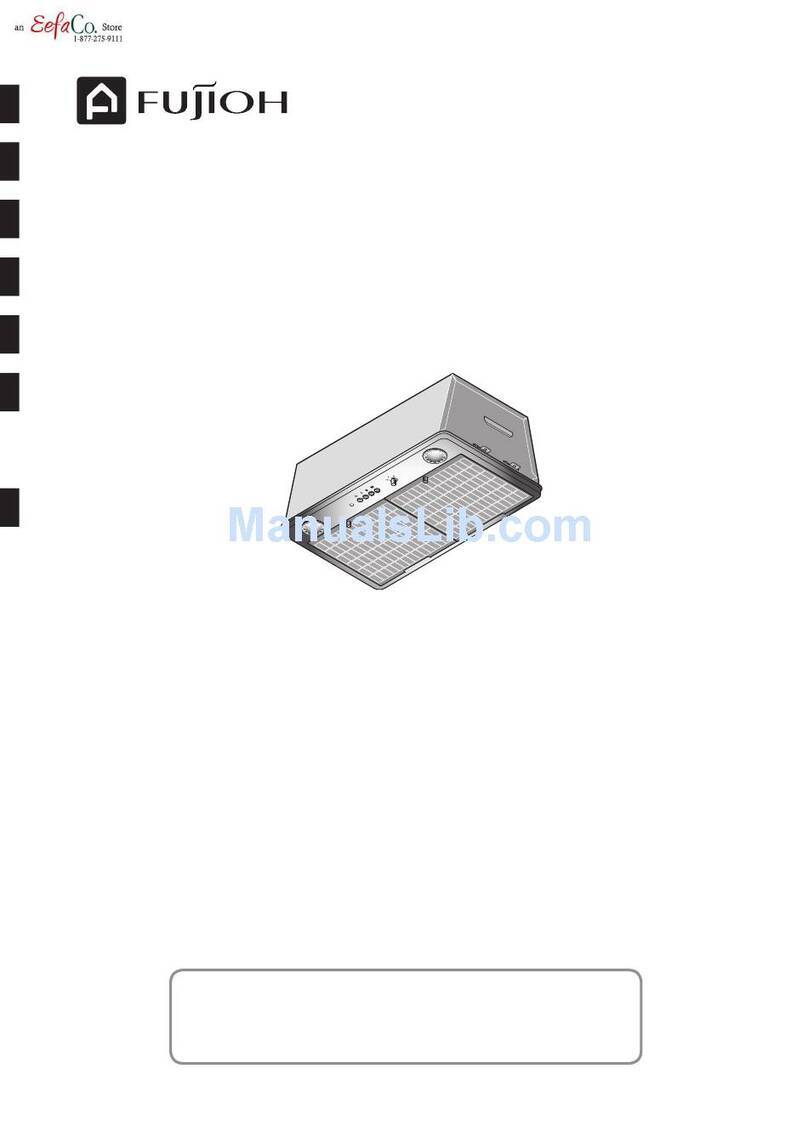
Fujioh MF-1100V User manual

MF-1100V
TABLE OF CONTENTS
1F03 1481
Thank you very much for your purchase of our cooker hood.
Before installing the cooker hood, please read this Manual thoroughly.
Keep this manual in a convenient place for future reference.
To the sales shop/installer:
After installing, please give
this manual to the user
without fail.
Safety Precautions ...........................2, 3
Preparation .......................................4, 5
Name of Parts ...............................................4
Dimensions....................................................5
Installation ......................................6~12
Preparation and Check before Mounting.......6
Cooker Hood Mounting .................................8
Attaching Duct Cover...................................10
Assembly.....................................................11
Operation Check..........................................12
Installation Manual
Cooker Hood
*1F031481*

2
Safety Precautions
Be sure to disconnect the power plug from the
wall outlet, or switch off the breaker when care
and maintenance. Also, don’t handle the power
plug or breaker with wet hand.
Electric shock or injury may result in.
Disconnect
the plug
Breaker
Never attempt to disassemble, repair, or modify.
Entrust them to the qualified technician, otherwise fire,
electric shock, or abnormal performance may occur.
When passing a metal duct through the wall composed of metal lath,
wire lath, or metal board, be careful not to touch these parts electrically.
Fire or electric shock may result in if leakage current flows.
Disassembly,
repair, or
modification
prohibited
Mounting work should be done by 2 persons minimum.
The weight of the cooker hood is about 34.5 kg.
Assembly
cautioned
Mounting
cautioned
Using
prohibited
Read the following safety instructions before mounting, and install the cooker hood properly and securely.
These instructions are for correct installation of the product to prevent any risk of hazards or damages inflicting on
you or others. The instructions are classified into 2 categories as "WARNING" and "CAUTION" depending on their
emergency and severity. Pay attention and strictly observe the instructions as they are critical for safety.
WARNING Alerts possible risk of death or serious injury, if not observed.
CAUTION Alerts possible risk of injury or physical damage, if not observed.
WARNING
means prohibition. It indicates actions, if any, that mustn't be done.
(Left symbol: Disassembly prohibited)
means forcible execution. It indicates actions, if any, that must be done.
(Left symbol: Disconnect the plug from the wall outlet)
Example
Electric wiring must be made properly by the professional installer or personnel.
Incorrect wiring may be cause of electric leakage or fire.
When dust accumulated on the blades of the power
plug or on their roots, wipe off well.
Fire may result in.
Don’t pour water on the electric parts.
Fire or electric shock may result in.
When there may be a gas leak in your gas hob,
don’t switch on or off the cooker hood.
Gas explosion may result in.
Choose a mounting location where sufficient air flow is
maintained.
CO poisoning may result if not ventilated adequately
while using a natural vent type stove, etc.
Wipe off
dust
Pouring
water
prohibited
Operation
prohibited
Air supply
cautioned
Assembly
cautioned
wet hand
Regulations concerning the discharge of air have to be fulfilled.
The air must not be discharged into a flue that is used for exhausting fumes
from appliances burning gas or other fuels.
(Not applicable to appliances that only discharge the air back into the room.)
Improper
discharge
prohibited
Observe
regulations
Don’t connect to the power voltage other than 220V/230V/240V AC.
Fire or electric shock may result in.
3
Safety Precautions
Be sure to disconnect the power plug from the wall outlet,
or switch off the breaker when not using for a long time.
Insulation may be deteriorated, and fire or electric shock may
result in.
Disconnect
the plug
Disconnect
by holding
the plug
Don’t touch the filter or parts around it while cooking.
The filter or parts may drop, and burn or injury may result in.
Mounting
cautioned
Using
prohibited
Assemble the fan or component parts securely.
Injury by dropping may result in.
Assembly
cautioned
Contact
prohibited
If the power cord is damaged, it must be replaced by the manufacturer,
its service agent or similarly qualified persons in order to avoid a hazard.
Switch off the cooker hood at once when oil caught fire
while cooking.
It’s dangerous if not stop as fire is built up.
Mount the product securely after selecting a solid place.
Dropping may result in injury.
Operation
prohibited
Wear gloves
Replace the
cord if it’s
damaged
CAUTION
When disconnecting the power plug, hold the plug itself.
Don’t pull the cord anyway.
The cord may be damaged, and fire or electric shock may
result in.
Assembly
cautioned
Contact
prohibited
Contact
prohibited
Be sure to wear gloves when care and maintenance.
Injury by the sharp edges or corners may result in.
Ensure that electric wiring is made safely according
to the standard or regulations related.
Incorrect wiring may result in fire or electrical shock.
Don’t touch the lamp cover or around it.
As it becomes high temperature, burning
may result in.
During operation, never insert fingers
or other objects.
Failure or injury may result in.
Never use the product in a wet place such as bath room, etc.
(Use a ventilation fan for bath room.)
It may be cause of fire or failure if used.
Mounting
cautioned
Improper
discharge
prohibited
The minimum distance between the supporting surface for the cooking vessels
on the hob and the lowest part of the cooker hood. When the cooker hood
is located above a gas appliance, this distance shall be at least 80cm. If the
instructions for installation for the gas hob specify a greater distance, this has
to be taken into account.
The air must not be discharged into a flue that is used for
exhausting fumes from appliances burning gas or other fuels
(not applicable to appliances that only discharge the air back into the room).

4
Preparation
Name of Parts
Preparation
Push-button switch
Rectifier panel
Body
Oil tray
Spice rack
Duct cover
Pilot lamp
Fan
Oil receving coverSlot filter
Power plug
Exhaust port (1)
Washer-head wood screw
(∅5.1×45) (4)
Duct cover (1)
Spice rack (1)
Screw (4)
Wood screw and washer (2)
Hanger (2)
Soft tape (1)
Vent cap (1)
Accessories

5
Preparation
40
20
30
30
300
267
150 30
110
160
270
380
(240) 25550
200
600
(35)
Roller
Catch
Duct cover fixing bracket
Connection hole
(For cooker hood)
Connection hole
(For duct cover fixing bracket)
Mounting hole
125
322
43
90
500 600
500
460
70
75
1008
1066 600 400
500
85
380 305
150
R3
R9
12
460
Power plug
Length : 1m or more
Dimensions (Unit: mm)
Standard Mounting Height
Mount the cooker hood at a place where more than 800mm between the surface of the gas range
and the bottom of the cooker hood is cleared. (800mm for optimum performance.)
90 30
90 30
(optimum performance)
800 or more than 800
500
(Unit: mm)

6
Installation
Preparation and Check before Mounting
1
Checking mounting surface strength
The mounting surface should have sufficient strength enough to support the cooker hood.
Mount the cooker hood on a place durable to support the weight of the cooker hood.
[Weight: 34.5 kg]
In the case of boarded wall
If the thickness is more than 20mm, mount the cooker hood directly to the wall.
If the thickness is less than 20mm, embed a reinforcing board and mount the cooker
hood to this board.
In the case of a concrete/tile faced wall
Embed a reinforcing board in the wall in advance, or use a curl plug or the like.
Installation
2
Power supply plug
The power plug of this cooker hood is 5A 3-pin plug (Type-BF: BS1363).
Be sure to use the wall outlet only for the cooker hood.
1. Mount the cooker hood carefully and avoid contact with any metal parts (the lath in
the wall or the like) of the building.
2. Never embed the body of the cooker hood in the wall. Otherwise, leakage current in
the wall, if any, flows to the body of the cooker hood.
3. The air must not be discharged into a flue that is used for exhausting fumes from
appliances burning gas or other fuels (not applicable to appliances that only discharge
the air back into the room).
4. The minimum distance between the supporting surface for the cooking vessels on the
hob and the lowest part of the cooker hood. When the cooker hood is located above
a gas appliance, this distance shall be at least 80cm.
If the instructions for installation for the gas hob specify a greater distance, this has to
be taken into account.
5. Use a gas range having a narrower width than that of the cooker hood.
6.
Avoid using the cooker hood with changes in the specification, for instance, with modifying
the switch.
7. Do not install the cooker hood in a wet area or in other wet rooms since it may result in
electric shock or damage.
8. Do not install the cooker hood at a place where its ambient temperature exceeds 40°C,
otherwise it may result in failure.
9. To protect your hands from injury, wear working gloves when installing the cooker hood.
10. If the power cord is damaged, it must be replaced by the manufacturer or its service
agent or a similarly qualified person in order to avoid a hazard.
11. If it's possible to touch the fan when inserting hand from the outer port of the exhaust
duct because its length is rather short, take some measures for preventing from
inserting hand.
CAUTION

7
Installation
Note
Place the range hood on the sheet etc.
in order not to scratch the floor.
3
Checking accessory parts
Take out the main unit and accessory parts (screws, exhaust port, etc.)
from the packing box, and check whether there is any shortage.
Note
When attaching the exhaust port, pay attention to its shutter opening direction.
If it's installed incorrectly, it may cause bad discharge, abnormal noise, etc.
6
Fixing the exhauset port
The fixing screws are supplied with attaching to
the top plate.
Insert the exhaust port to the insertion slot on
the top of the enclosure, and fix using 2 screws.
Then attach the supplied soft tape around the
exhaust port.
5
Fixing the hangers
The fixing screws are supplied with attaching
to the top plate.
Firmly fix the hangers by fastening truss head
machine screws (M5×10).
Hanger
Soft tape
Insertion slot
Correct Wrong
4
Preparing exhaust duct
1) Referring to "Dimensions" on page 5, make a hole on the wall for exhaust duct.
2) Set ∅150 stainless or spiral duct to the top of the cooker hood as shown, and perform finish
work around it. (In case of the concrete, tile, and mud wall.)
30~50
(Unit: mm)
125
Center line

8
Installation
2
Mount the body
Hook the keyholes of the hanger on the
washer-head wood screws, and tighten
the screws.
Cooker Hood Mounting
1
Screw in washer-head wood screws on the wall
Referring to "Dimensions" on page 5, insert the washer-head
wood screws (∅5.1×45) into the mounting wall for the left and
right keyholes of the hanger. Allow about 5mm space between
the wall and screwheads for hanging the cooker hood.
Washer-head
wood screw
Keyhole
5mm
Washer-head
Wood screw
3
Removing oil receiving cover
Grasp the oil receiving cover with one hand
at each end. Pull the top of the cover out
and down, and then lift the bottom of the
cover to detach it from the body.
Oil receiving cover
Catch
Note
Please use suitable accessories during installation
(refer to page 4).
May add or opt for other accessories as reinforcement
when necessary.

9
Installation
Washer-head
Wood screw
5
Fix the body
Put 2 washer-head wood screws
(∅5.1×45) to the rear of the body and
tighten them securely.
6
Connection of duct and exhaust port
Connect ∅150 flexible tube duct or the like
with the exhaust port.
Make the exhaust port secure and air-tight
using non-flammable tape such as aluminium
tape, etc. (not supplied)
Note
The longer the exhaust duct, the lower the ventilation.
Frexible tube duct
Ta ping with non-flammable
materials (Alminum tape etc.)
Note
In order not to drop the rectifier panel,
hold it by both hands securely. If
dropped, it may be a cause of injury,
flaw or warp of parts, etc.
4
Removing rectifier panel
Loosen the mounting screws attaching
the rectifier panel, move the rectifier
panel upward slightly to free the
mounting screws from the mounting
guide holes and the body catches.
Rectifier panel
Mounting guide hole
Mounting screw
Catch

10
Installation
2mm
Fixing screw
Attaching Duct Cover
1
Disassembling duct cover
Remove the front panel and duct cover
fixing bracket from the duct cover supplied.
Note
In case of upper discharge, remove the
top plate also.
2
Fastening duct cover fixing bracket
Using the height of the duct cover for
alignment, fasten the duct cover fixing
bracket to the wall using the 2 wood
screws and washers supplied (Do not
fasten the screws tightly).
Note
When attaching the duct cover fixing
bracket to the wall, there are three holes
in the bracket. Use the two holes at the
outer edge of the bracket, do not use the
center hole.
Fixing screw
Fixing screw
Duct cover
Front panel
To p plate
Duct cover
fixing bracket
Roller catch
Duct cover height
(Standard: 530)
30
Wood
screw
Washer
Exhaust duct
Duct cover
fixing bracket
3
Fixing duct cover
1) Insert supplied 4 screws on the top of the
enclosure as shown. Be sure to keep about
2mm space between the top and screw-
head.
2) Put the duct cover with aligning its 4 bottom
cutouts with the screws, slide it backward,
then tighten 4 screws securely.
3) Fix the upper left and right sides of the
duct cover to the duct cover fixing bracket
with 2 screws.
4) Tighten 2 wood screws for the duct cover
fixing bracket firmly.
Fixing screw
Wood screw

11
Installation
Assembly
2
Attaching rectifier panel
Holding the rectifier panel with both hands,
place the rear of the panel in front of the
catches and in line with the mounting
guide holes. Then slide the panel back to
engage the mounting guides and attach
the catches.
Tighten the mounting screw to attach the
panel firmly.
Note
Make sure that the rectifier panel is fixed
securely. It may be a cause of dropping
if not fixed firmly.
Note
In case of backward discharge,
re-assemble the top plate.
Catch
Mounting guide hole
Mounting screw
Rectifier panel
1
Stripping off the fixing tape
Strip off the oil tray fixing tape.
Fixing tape
Oil tray
4
Attaching front panel
Replace the front panel with engaging its
top notches first, then pushing its bottom to
set into the roller catch.
Front panel
3
Attaching oil receiving cover
Holding the oil receiving cover with one
hand at each end, align the slits on the
bottom panel of the body with the slits on
the cover. Swivel the top part of the cover
up and to the body in the direction shown
by the arrow. Make sure that the catches
at both ends of the oil receiving cover are
firmly latched.
Catch
Oil receiving cover

12
Installation
1
Power supply
Connect the power plug to the wall outlet (220V/230V/240V AC).
2
Operation check
1) While operating the cooker hood by pushing the applicable control switches,
check the air flow or presence of abnormal vibration or the like.
2) The lamp is turned ON and OFF when the LIGHT control switch is pushed,
refer to the operation manual for details.
Operation Check
4
Attaching Vent cap
Put a vent cap on the duct end outside
as a rain cover.
Vent cap
Duct

MF-1100V
內容目錄
1F03 1481
非常感謝購買我們的抽油煙機。
在安裝抽油煙機之前,請先通讀本手冊。
請將本手冊保存在方便的地方以備隨時參考。
代銷店 / 安裝人員請注意:
安裝後,請務必把本手冊
交給用戶。
安全措施 ...........................................2, 3
準備 ..................................................4, 5
零件的名稱 ....................................................4
尺寸 ...............................................................5
安裝 ................................................6~12
安裝前的準備和檢查 ......................................6
安裝抽油煙機 ................................................8
安裝導管罩 ..................................................10
組 裝 ...........................................................11
運行檢查 ......................................................12
安裝手冊
抽油煙機
*1F031481*

2
安全措施
表示禁止。所述的行為(如果有)是絕對不能做的。
(左圖:禁止拆卸)
表示強制執行。所述的行為(如果有)是必須做的。
(左圖:把插頭從牆上的插座中拔出)
維修保養時必須把插頭從牆上的插座中拔出,或切斷
電源開關。同時,請不要用濕手摸插頭或電源開關。
會有導致觸電或受傷的危險。
拔出插頭
抽油煙機
專用
電源開關
不要嘗試拆卸、修理、或改裝。
必須請技術人員操作,否則會有起火,觸電,或異常事故發生。
在把金屬導管穿過有鋼筋、金屬線、或金屬板的牆壁時,
請注意不能讓電流碰到這些金屬部分。
如果有漏電流流過將有發生起火,觸電的危險。
禁止拆卸
修理或改裝
安裝作業必須有至少 2 人以上進行。
抽油煙機的重量約 34.5kg。
裝配時注意
安裝時注意
禁止使用
請在安裝前仔細閱讀下述安全事項,正確安全地安裝抽油煙機。
下述安全事項是為了正確地安裝本產品,以免使您和其他人遭受危險或負傷。
安全事項根據緊急性和重要性的程度分為“警告”和“注意”2 類。
請予以重視並嚴格按照說明指示操作。
警告
知會如果不遵守將有機會發生死亡或受重傷的危險。
注意
知會如果不遵守將有機會發生受傷或人體損害的危險。
警告
例
電線必須由專業安裝公司或人員正確地佈線。
不正確的佈線可能會導致漏電或起火等事故。
插頭的插件或插頭坐上有灰塵時,請清潔乾淨。
會有導致起火的危險。
不要注水到通電部分。
會有導致起火,觸電的危險。
在爐具有漏氣的可能性時,不要打開或關上抽油煙機。
會有引起氣體爆炸的危險。
務必安裝在空氣流通順暢的地方。
在使用自然通風型爐灶等時,如果通風不暢會引起煤氣中毒。
清潔灰塵
禁止注水
禁止運行
注意
空氣流通
裝配時注意
必須遵守有關排氣的規定。
空氣不得排入用於排放燃氣或其他燃料設備廢氣的煙道。
(只將空氣排放到室內的家電除外)
禁止
不當排氣
遵守規定
不要連接到高於 220V/230V/240V 電壓的電源上。
會有導致起火、觸電的危險。

3
安全措施
抽油煙機
專用
長期不使用時務必把插頭從牆上的插座中拔出,或切斷電源開關。
可能因絕緣體的劣化而導致起火或觸電的危險。
拔出插頭
拿住插頭
拔出
做飯時不要觸動過濾器或其周圍的部分。
過濾器或其周圍的部分可能會滴油,從而造成燒傷或傷害。
安裝時注意
禁止使用
安全地安裝排風扇或其他配件。
會有導致起火或觸電的危險。
裝配時注意
禁止觸摸
如果電源線有破損,必須由製造商、製造商的代理
或具備相同資格的人來更換,以免出現危險。
在做飯時發生油著火的情況,請立即關掉抽油煙機。
如果不立即關掉會有助長火勢的危險。
選擇牢固的地方安全地安裝本產品。
落下會造成傷害。
禁止運行
戴手套
更換
破損電線
注意
在拔出插頭時,請拿著插頭拔,不要拉電線部分。
電線容易破損,會有導致起火或觸電的危險。
裝配時注意
禁止觸摸
禁止觸摸
在維修保養時務必戴上手套。
銳利的邊緣或拐角可能引起受傷。
必須保證電線是按照相關的標準或規定佈線的。
不正確的佈線會導致起火或觸電的危險。
不要觸摸燈罩或其周圍的部分。
可能因高溫導致燙傷。
運行時,絕對不要把手指或其他物體插進去。
會有導致破損或受傷的危險。
絕對不要在浴室等潮濕的地方使用本產品。(浴室請使用排氣扇。)
會有導致起火或觸電的危險。
安裝時注意
禁止
不當排氣
爐具上支架的表面與抽油煙機最低部分的最小距離限度。
如果抽油煙機安裝在燃氣爐具上方時,這個距離應至少在 80 厘米以上。
如果燃氣爐具的安裝說明指定一個更高的距離時,請酌情考慮。
空氣不得排入用於排放燃氣或其他燃料設備廢氣的煙道。
(只將空氣排放到室內的家電除外)

4
準備
零件的名稱
準備
按鍵開關
整流板
機體
儲油盤
調味品架
導管罩
指示燈
排風扇
集油蓋
過濾網
電源插頭
排氣口 (1)
華司頭木螺絲
(∅5.1×45)(4)
導管罩(1)
調味品架(1)
螺絲(4)
木螺絲和墊圈(2)
掛具(2)
軟帶 (1)
排風罩 (1)
附件

5
準備
40
20
30
30
300
267
150 30
110
160
270
380
(240) 25550
200
600
(35)
導管罩固定架
連接孔
(抽油煙機用)
滾珠扣
連接孔
(導管罩固定架用)
裝配孔
125
322
43
90
500 600
500
460
70
75
1008
1066 600 400
500
85
380 305
150
R3
R9
12
460
電源插頭
線長:1米以
尺寸
(單位 : mm)
標準安裝高度
抽油煙機的安裝必須保持爐具的表面與抽油煙機的底部相距 800mm 以上。(800mm 性能最佳。)
90 30
90 30
(性能最佳)
800或800以上
500
(單位 : mm)

6
安裝
安裝前的準備和檢查
1
檢查安裝面的強度
安裝面必須保持足夠的強度可以支撐抽油煙機。
把抽油煙機安裝在可承受抽油煙機重量的地方。
[ 重量:34.5kg〕
牆面是石膏板的情況
如果石膏板厚超過 20mm,可以直接安裝到牆壁上。
如果石膏板厚不到 20mm,請嵌入一張加強輔助板,然後把抽油煙機安裝到輔助板上。
牆面是混凝土 / 瓷磚的情況
預先嵌入一張加強輔助板,或者使用嵌牆器具等。
安裝
2
電源插頭
抽油煙機的電源插頭為 5A 型 3 腳插頭(Type-BF:BS1363)。
只能使用牆壁電源插座。
1. 仔細安裝抽油煙機,避免與建築裡的任何金屬部分(牆壁裡的鋼筋等)接觸。
2. 絕對不要把抽油煙機的機體嵌入牆裡。否則如果牆裡有電流會傳到抽油煙機主機上。
3. 空氣不得排入用於排放燃氣或其他燃料設備廢氣的煙道。
(只將空氣排放到室內的家電除外)
4. 爐具上支架的表面與抽油煙機最低部分的最小距離限度。
如果抽油煙機安裝在燃氣爐具上方時,這個距離應至少在 80 厘米以上。
如果燃氣爐具的安裝說明指定一個更高的距離,請酌情考慮。
5. 使用小於抽油煙機寬度的燃氣爐具。
6. 避免使用改變規格的抽油煙機,例如開關被改裝等。
7. 不要把抽油煙機安裝在潮濕的地方或其他潮濕的室內,以免引起觸電或破損。
8. 不要把抽油煙機安裝在環境溫度超過 40 度的地方,以免引起產品功能異常。
9. 為了保護雙手不受傷,安裝時請戴上手套。
10. 如果電源線破損,須由製造商或其服務代理商或具有相同資格的人員更換,以避免
造成傷害。
11. 如果因為排氣導管太短,可以從出口處伸進手觸摸到排風扇時,請採取有效的措施
防止手伸進去。
注意

7
安裝
注
按照圖示把抽油煙機放在墊布等保護物
上以避免刮傷地板。
3
檢查附件配件
把主機和附件配件(螺絲,排氣口等)從包裝箱中取出,檢查有無短缺。
注
在安裝排氣口時,請注意排氣口擋板的開口方向。如果排氣口安裝不正確可能
導致排氣功能降低,產生異常噪音等不良現象。
6
固定排氣口
把提供的固定螺絲安裝到頂板上。
把排氣口插在外殼的頂部上,用 2 個螺絲固定好。
之後,把提供的軟帶裝貼到排氣口周圍。
5
固定掛具
把提供的固定螺絲安裝到頂板上。
擰緊構架頭機械螺絲 (M5×10),把掛具固定牢。
掛具
軟帶
插槽
正確 錯誤
4
準備排氣管
1) 參照 5 頁的“尺寸”,在牆上開一個安裝排氣管的孔。
2) 參照下圖把 φ150 不鏽鋼或螺旋導管安裝到抽油煙機的頂端,並完成相關作業。
(如果牆面是混凝土,瓷磚,和泥牆的情況。)
30~50
125
中心線
(單位: mm)

8
安裝
2
裝配機體
把抽油煙機的掛鉤鍵孔掛到華司頭木螺絲
上,並擰緊螺絲。
安裝抽油煙機
1
把華司頭木螺絲釘到牆裡
請參照第 5 頁“尺寸”,把華司頭木螺絲 (Φ5.1×45) 插入安裝
牆面上的掛具的左右兩個鍵孔中。請在牆面和螺絲頭之間預留
5mm 的空間用來掛抽油煙機。
鍵孔 華司頭木螺絲
5mm
華司頭木螺絲
3
取下集油蓋
兩手分別抓住集油蓋的兩邊。把集油蓋的頂
部朝下拉出來,然後把後部從機體中脫離出
來。
集油蓋
扣拴
注
安裝工序需要因應不同環境配合適當
零配件安裝(請參照第 4 頁),需要時
可另行加裝其他零配件。
Other manuals for MF-1100V
1
Table of contents
Other Fujioh Ventilation Hood manuals

Fujioh
Fujioh FSR-3000 User manual

Fujioh
Fujioh GFP-600 User manual

Fujioh
Fujioh FR-MT1990V User manual

Fujioh
Fujioh BUF-01 User manual

Fujioh
Fujioh FX-900 User manual

Fujioh
Fujioh BUF-06W User manual

Fujioh
Fujioh FX-900 User manual

Fujioh
Fujioh BUF-01M User manual

Fujioh
Fujioh BUF-021 User manual

Fujioh
Fujioh BUF-03R User manual

Fujioh
Fujioh FR-HT2190V Manual

Fujioh
Fujioh FR-SC2090/11 User manual

Fujioh
Fujioh FDR-4200 User manual

Fujioh
Fujioh EBW-600 User manual

Fujioh
Fujioh FDK-04A User manual

Fujioh
Fujioh BUF-03A User manual

Fujioh
Fujioh FR-ST2190VP User manual

Fujioh
Fujioh FR-FS1870V User manual

Fujioh
Fujioh BUF-04J User manual

Fujioh
Fujioh BUF-06P User manual