manuals.online logo
Brands
  1. Home
  2. •
  3. Brands
  4. •
  5. Aritech
  6. •
  7. Fire Alarm
  8. •
  9. Aritech 2X Series User manual

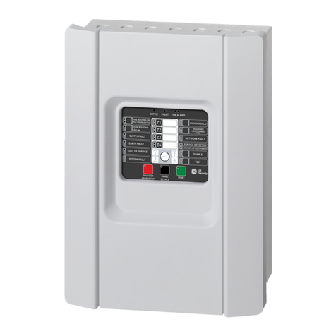
Aritech 2X Series User manual

© 2019 UTC Fire & Security. All rights reserved. 1 / 2 P/N 00-3250-507-0003-05 • ISS 03DEC19
2X Series Quick Installation Guide
Overview
This document includes quick installation information for your
control panel. For detailed installation information (including
EN 54-13 requirements) and for configuration options, see the
product installation manual.
WARNING: Electrocution hazard. To avoid personal injury or
death from electrocution, remove all sources of power and
allow stored energy to discharge before installing or removing
equipment.
Caution: Equipment damage hazard. This product is sensitive
to electrostatic discharge (ESD). To avoid damage, follow
accepted ESD handling procedures.
Adding the menu inserts
Add the control panel interface menus as shown below.
The inserts are numbered 1, 2, 3, and 4, and are inserted at
the location indicated (with the printed area facing the front of
the control panel).
For evacuation panels, remember to add descriptions for any
output groups assigned to the programmable buttons to
insert 3.
Note: Different versions of insert 3 are provided for fire panels
and for evacuation panels, and each is marked with the
corresponding control panel product code. Be sure to use the
correct version of the insert for your product.
Installing the cabinet
Where to install the control panel
Install the control panel in a location that is free from
construction dust and debris, and immune to extreme
temperature ranges and humidity.
Provide enough floor and wall space to allow the control panel
to be installed and serviced without any obstructions. The
cabinet should be mounted so that the user interface is at eye
level.
Fixing the cabinet to the wall
Fix the cabinet to the wall using five M4 × 30 screws and five
Ø 6 mm wall plugs, as shown below.
1. Hold the cabinet to the wall at the required installation
height.
2. Ensure that the cabinet is level using the built-in spirit level
and mark drill points on the wall.
3. Drill all required holes and insert a 6 mm wall plug into
each.
4. Insert a screw in position (1) and hang the cabinet onto
this screw.
5. Insert screws in positions (2) and tighten.
6. Insert screws in position (3) and tighten.
7. Tighten screw in position (1).
2 / 2 P/N 00-3250-507-0003-05 • ISS 03DEC19
Overview of typical fire system connections using a single Class A loop
Connecting loops and loop devices
For optimal system performance, we recommend a shielded
loop cable, 12 to 26 AWG (0.13 to 3.31 mm²), with 52 Ω (26 Ω
per wire) and 500 nF/km maximum.
Class A loops are supervised for open and short circuits.
Terminate unused Class A loops A (+) to B (+) and A (−) to
B (−). Each Class A loop can support up to 128 devices.
See the product installation manual for Class B loop
connection information.
Connecting inputs and outputs
Caution: The following connection information does not apply
to installations requiring EN 54-13 compliance. If EN 54-13
compliance is required, see the product installation manual.
All inputs and outputs (except 24V AUX) require a 15 kΩ end-
of-line resistor for termination to detect open or short circuits. If
an input or output is not used, install a 15 kΩ end-of-line
resistor across the unused terminals to avoid an open circuit
fault.
Connect input switches to INPUT1 and INPUT2 (62 Ω ≤active
value ≤8 kΩ).
When connecting outputs, observe polarity or install a 1N4007
diode or equivalent to avoid inverted activation issues.
See the product installation manual for input and output
configuration options.
Mains fuse and batteries
Use a T4A-250V mains fuse for both 110 VAC and 240 VAC
operation. Check the product installation manual for 110 VAC
operation requirements.
The control panel requires two 12 V, 7.2, 12, or 18 Ah
rechargeable sealed lead-acid batteries.
For detailed battery requirements, see the product installation
manual.
Configuration
See your product installation manual for detailed configuration
information. The default installer password is 4444.
Contact information and product
documentation
For contact information or to download the latest product
documentation, visit firesecurityproducts.com.
Product warnings and disclaimers
THESE PRODUCTS ARE INTENDED FOR SALE TO AND INSTALLATION BY
QUALIFIED PROFESSIONALS. UTC FIRE & SECURITY CANNOT PROVIDE
ANY ASSURANCE THAT ANY PERSON OR ENTITY BUYING ITS
PRODUCTS, INCLUDING ANY “AUTHORIZED DEALER” OR “AUTHORIZED
RESELLER”, IS PROPERLY TRAINED OR EXPERIENCED TO CORRECTLY
INSTALL FIRE AND SECURITY RELATED PRODUCTS.
For more information on warranty disclaimers and
product safety information, please check
https://firesecurityproducts.com/policy/product
-
warning/
or scan the QR code:

Other manuals for 2X Series

2

This manual suits for next models

2

Other Aritech Fire Alarm manuals

Aritech 2X-F1 User manual

Aritech

Aritech 2X-F1 User manual

Aritech 1200C User manual

Aritech

Aritech 1200C User manual

Aritech 1X-F Series User guide

Aritech

Aritech 1X-F Series User guide

Aritech 2X-F1 User guide

Aritech

Aritech 2X-F1 User guide

Aritech 2X-A Series User guide

Aritech

Aritech 2X-A Series User guide

Aritech 900 Series User manual

Aritech

Aritech 900 Series User manual

Aritech 2X Series User manual

Aritech

Aritech 2X Series User manual

Aritech 2X-F2-FB2-S-32 User guide

Aritech

Aritech 2X-F2-FB2-S-32 User guide

Aritech 2X-AF2-FB-PRT-P User manual

Aritech

Aritech 2X-AF2-FB-PRT-P User manual

Aritech DM2010 Assembly instructions

Aritech

Aritech DM2010 Assembly instructions

Aritech 2X Series User manual

Aritech

Aritech 2X Series User manual

Aritech FP2000 User manual

Aritech

Aritech FP2000 User manual

Popular Fire Alarm manuals by other brands

HST HS201 Installation and maintenance  instruction

HST

HST HS201 Installation and maintenance instruction

Isimet FLA Series Installation, Operations, Start-up and Maintenance Instructions

Isimet

Isimet FLA Series Installation, Operations, Start-up and Maintenance Instructions

Teletek electronics SensoIRIS MCP150PR installation instructions

Teletek electronics

Teletek electronics SensoIRIS MCP150PR installation instructions

Ampac FireFinder NZS 4512 installation guide

Ampac

Ampac FireFinder NZS 4512 installation guide

United Technologies Kidde VS1 quick start guide

United Technologies

United Technologies Kidde VS1 quick start guide

Notifier NFS-640 Operation manual

Notifier

Notifier NFS-640 Operation manual

Eurofyre ProFyre C8 User & Maintenance Guide + Log Book

Eurofyre

Eurofyre ProFyre C8 User & Maintenance Guide + Log Book

Firesense IFS-888 OPERATORS & PROGRAMMING MANUAL

Firesense

Firesense IFS-888 OPERATORS & PROGRAMMING MANUAL

Kidde FX-64 Technical reference manual

Kidde

Kidde FX-64 Technical reference manual

Mircom FleX-Net FX-2003-12NDS Installation and operation manual

Mircom

Mircom FleX-Net FX-2003-12NDS Installation and operation manual

Simplex 4100ES-S1 Installation & maintenance

Simplex

Simplex 4100ES-S1 Installation & maintenance

Mircom MPS-800MPU Series Guide

Mircom

Mircom MPS-800MPU Series Guide

technoswitch AP-DIS-MCP2 manual

technoswitch

technoswitch AP-DIS-MCP2 manual

Comelit 48CME100 Technical manual

Comelit

Comelit 48CME100 Technical manual

Task Force Tips CROSSFIRE Instructions for installation, operation, maintenance

Task Force Tips

Task Force Tips CROSSFIRE Instructions for installation, operation, maintenance

Zeta ZIOU user manual

Zeta

Zeta ZIOU user manual

Honeywell ESSER 804902 Installation instruction

Honeywell

Honeywell ESSER 804902 Installation instruction

Pittway Notifier AM2020 troubleshooting guide

Pittway

Pittway Notifier AM2020 troubleshooting guide

manuals.online logo
manuals.online logoBrands
  • About & Mission
  • Contact us
  • Privacy Policy
  • Terms and Conditions

Copyright 2025 Manuals.Online. All Rights Reserved.