manuals.online logo
Brands
  1. Home
  2. •
  3. Brands
  4. •
  5. Aritech
  6. •
  7. Fire Alarm
  8. •
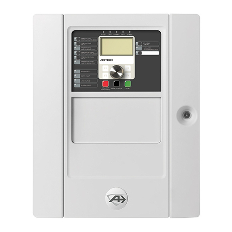
  9. Aritech 2X Series User manual

Aritech 2X Series User manual

© 2013 UTC Fire & Security. All rights reserved. 1 / 2 P/N 501-405003-4-30 • REV 03 • ISS 23FEB13
2X Series Quick Installation Guide
Overview
This document includes quick installation information for your
control panel. For detailed installation information (including
EN 54-13 requirements) and for configuration options, see the
product installation manual.
WARNING: Electrocution hazard. To avoid personal injury or
death from electrocution, remove all sources of power and
allow stored energy to discharge before installing or removing
equipment.
Caution: Equipment damage hazard. This product is sensitive
to electrostatic discharge (ESD). To avoid damage, follow
accepted ESD handling procedures.
Adding the menu inserts
Add the control panel interface menus as shown below.
The inserts are numbered 1, 2, 3, and 4, and are inserted at
the location indicated (with the printed area facing the front of
the control panel).
For evacuation panels, remember to add descriptions for any
output groups assigned to the programmable buttons to
insert 3.
Note: Different versions of insert 3 are provided for fire panels
and for evacuation panels, and each is marked with the
corresponding control panel product code. Be sure to use the
correct version of the insert for your product.
Installing the cabinet
Where to install the control panel
Install the control panel in a location that is free from
construction dust and debris, and immune to extreme
temperature ranges and humidity.
Provide enough floor and wall space to allow the control panel
to be installed and serviced without any obstructions. The
cabinet should be mounted so that the user interface is at eye
level.
Fixing the cabinet to the wall
Fix the cabinet to the wall using five M4 × 30 screws and five
Ø 6 mm wall plugs, as shown below.
1. Hold the cabinet to the wall at the required installation
height.
2. Ensure that the cabinet is level using the built-in spirit level
and mark drill points on the wall.
3. Drill all required holes and insert a 6 mm wall plug into
each.
4. Insert a screw in position (1) and hang the cabinet onto
this screw.
5. Insert screws in positions (2) and tighten.
6. Insert screws in position (3) and tighten.
7. Tighten screw in position (1).
2 / 2 P/N 501-405003-4-30 • REV 03 • ISS 23FEB13
Connecting loops and loop devices
For optimal system performance, we recommend a twisted-pair
loop cable, 12 to 26 AWG (0.13 to 3.31 mm²), with 52 Ω (26 Ω
per wire) and 500 nF/km maximum.
Class A loops are supervised for open and short circuits.
Terminate unused Class A loops A (+) to B (+) and A (−) to
B (−). Each Class A loop can support up to 128 devices.
See the product installation manual for Class B loop
connection information.
Connecting inputs and outputs
Caution: The following connection information does not apply
to installations requiring EN 54-13 compliance. If EN 54-13
compliance is required, see the product installation manual.
All inputs and outputs (except 24V AUX) require a 15 kΩ end-
of-line resistor for termination to detect open or short circuits. If
an input or output is not used, install a 15 kΩ end-of-line
resistor across the unused terminals to avoid an open circuit
fault.
Connect input switches to INPUT1 and INPUT2 (62 Ω ≤active
value ≤8 kΩ).
When connecting outputs, observe polarity or install a 1N4007
diode or equivalent to avoid inverted activation issues.
See the product installation manual for input and output
configuration options.
Mains fuse and batteries
Use a T4A-250V mains fuse for both 110 VAC and 240 VAC
operation. Check the product installation manual for 110 VAC
operation requirements.
The control panel requires two 12 V, 7.2, 12, or 18 Ah
rechargeable sealed lead-acid batteries. For detailed battery
requirements, see the product installation manual.
Configuration
See your product installation manual for detailed configuration
information. The default installer password is 4444.
Contact information
For contact information, see www.utcfssecurityproducts.eu.
Overview of typical fire system connections using a single Class A loop

Other manuals for 2X Series

2

This manual suits for next models

2

Other Aritech Fire Alarm manuals

Aritech 1200C User manual

Aritech

Aritech 1200C User manual

Aritech 2X-F1 User manual

Aritech

Aritech 2X-F1 User manual

Aritech 1X-F Series User guide

Aritech

Aritech 1X-F Series User guide

Aritech 2X Series User manual

Aritech

Aritech 2X Series User manual

Aritech 2X-F1 User guide

Aritech

Aritech 2X-F1 User guide

Aritech 2X-A Series User guide

Aritech

Aritech 2X-A Series User guide

Aritech 2X-F2-FB2-S-32 User guide

Aritech

Aritech 2X-F2-FB2-S-32 User guide

Aritech 900 Series User manual

Aritech

Aritech 900 Series User manual

Aritech FP2000 User manual

Aritech

Aritech FP2000 User manual

Aritech 2X-AF2-FB-PRT-P User manual

Aritech

Aritech 2X-AF2-FB-PRT-P User manual

Aritech 2X Series User manual

Aritech

Aritech 2X Series User manual

Aritech DM2010 Assembly instructions

Aritech

Aritech DM2010 Assembly instructions
Popular Fire Alarm manuals by other brands

Honeywell Fire-Lite Alarms BG-12S manual

Honeywell

Honeywell Fire-Lite Alarms BG-12S manual

Panasonic EBL128 Planning Instructions

Panasonic

Panasonic EBL128 Planning Instructions

Johnson Controls SWIFT instruction manual

Johnson Controls

Johnson Controls SWIFT instruction manual

Ampac ACP-02 installation guide

Ampac

Ampac ACP-02 installation guide

Zeta ZIOU user manual

Zeta

Zeta ZIOU user manual

Consilium CFD5000 FDS user manual

Consilium

Consilium CFD5000 FDS user manual

Siemens FC2005 Programming manual

Siemens

Siemens FC2005 Programming manual

Notifier ONYX Series manual

Notifier

Notifier ONYX Series manual

Honeywell SILENT KNIGHT 5860 Product installation document

Honeywell

Honeywell SILENT KNIGHT 5860 Product installation document

Bosch FMC-420RW-GSRRD installation guide

Bosch

Bosch FMC-420RW-GSRRD installation guide

Apollo SA5900-908 installation guide

Apollo

Apollo SA5900-908 installation guide

Honeywell Apex Step-by-Step

Honeywell

Honeywell Apex Step-by-Step

Notifier UniNet 2000 AFP-300 NION instruction manual

Notifier

Notifier UniNet 2000 AFP-300 NION instruction manual

Evacuator Defender Wireless Alarm instructions

Evacuator

Evacuator Defender Wireless Alarm instructions

Vighnaharta Master Control Unit user manual

Vighnaharta

Vighnaharta Master Control Unit user manual

Gent Xenex 13270-02LB Operating instructions and Log Book

Gent

Gent Xenex 13270-02LB Operating instructions and Log Book

Pittway System Sensor V4R24ADA Series Installation and maintenance instructions

Pittway

Pittway System Sensor V4R24ADA Series Installation and maintenance instructions

Channel Safety Systems Rapidfire instruction manual

Channel Safety Systems

Channel Safety Systems Rapidfire instruction manual

manuals.online logo
manuals.online logoBrands
  • About & Mission
  • Contact us
  • Privacy Policy
  • Terms and Conditions

Copyright 2025 Manuals.Online. All Rights Reserved.