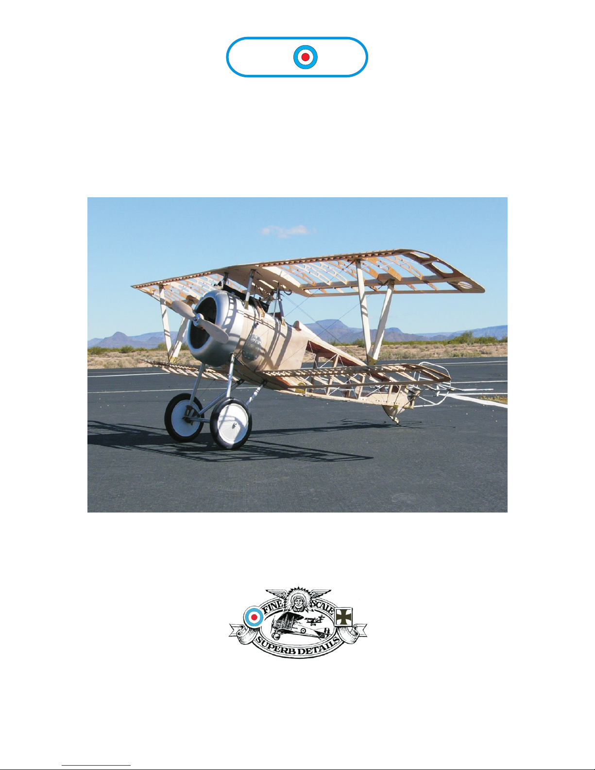
Arizona DIEUPORT 17 Quick start guide

N
A
RIZ
A
Model Aircrafters
www.arizonamodels.com
Assembly Notes
A registered tradename of Digital Design LLC.
13814 N. 56th Place, Scottsdale Arizona 85254.
Nieuport 17 & 23


Crankcase Assembly Detail
(Skip for fiberglass crankcase)
Stack parts a-d as shown in the drawing. Use the pins
included in the kit for cosmetics after the wood parts are sealed.
Parts D and E are spaced apart using the wire
make sure that all the formers are centered to each other.
Attach rear former F centering on the three holes provided.
Use additional pieces of the wire to secure E to F.
Finish the crank case by attaching parts G
as shown. Sand the joints between parts F
to a rounded edge fill as necessary. Attach
the cylinders as per the version engine you
are building. Early LeRhones had the pushrod
mounted into the front of the crankcase
(part B) later LeRhones had the cylinders
rotated placing the pushrods to the rear
(photo) to protect the mechanism from flack
and gunfire.
Pushrods are scratch
from 1/16 aluminum tubing
with 1/8 tube section for the
bottom slide. The pushrods mount
to the top lever by slotting the
end of the tube and cross drilling
to make a clevis. File the plastic
levers to accommodate and secure
with a nut and bolt. Use the laser
cut rocker arms Large for Gnome
small for the LeRhone and Clerget
Cylinder Head Modifications
(all cylinder types)
Gnome Engines:
Omit the manifold pipe.
LeRhone engines had copper
manifolds.
Use plastic tubing reenforced
with an internal wire to make
the manifold. We used tubing
from a drip irrigation system
we found at our local hardware
store.
exhaust pipe gasket
Exhaust pipe gasket
Front Side
Top cooling fins omitted for clarity.
Step 1
Wire wrapped around tube
to simulate pipe seam.
LeRhone Aircraft Engine
ALL SCALES CONSTRUCTION DIAGRAM
With Clerget and Gnome variations
COMPONENTS OF THIS DESIGN GRAPHIC AND REPRESENTATION ARE REPRODUCED
WITH THE PERMISSION OF WWI AERO AND AIR AGE PUBLICATIONS
ARIZONA MODEL AIRCRAFTERS
A registered tradename of Digital Design LLC.
13814 N. 56th Place, Scottsdale Arizona 85254
Step 2
Use epoxy for assembly
AB1- B4 C D E F1
Stack as necessary
SHEET 1 of 3
Copywrite 2006 by Arizona Model Aircrafters
a registered tradename of Digital design LLC
N
A
RIZ
A
Model Aircrafters
www.arizonamodels.com
9 Cylinder Rotary
Assembly All Scales
LeRhone & Gnome

Final Engine Assembly
Make sure that the cylinders are secure to the crankcase.
Shown above in the illustration is a LeRhone configuration of
the kit. note that the cylinder as shown has the
pushrods to the back and has an additional piece of tubing
installed to simulate the exhaust pipe. Pushrods on Gnomes and early
LeRhones were installed to the front. Check your scale
documentation for the correct method of assembly.
Assemble the Williams Brothers engine cylinders as per directions. Engine Cylinders
can be modified to build as a Gnome or Clerget refer to photos of the engine or call
for assistance and additional technical support.
Brass Hardware
Step 3
Side
View
C/L
Some designs require an additional
part “B”. Additional parts available.
Fill if not used
9 Cylinder Gnome
LeRhone Aircraft Engine
ALL SCALES CONSTRUCTION DIAGRAM
With Clerget and Gnome variations
COMPONENTS OF THIS DESIGN GRAPHIC AND REPRESENTATION ARE REPRODUCED
WITH THE PERMISSION OF WWI AERO AND AIR AGE PUBLICATIONS
ARIZONA MODEL AIRCRAFTERS
A registered tradename of Digital Design LLC.
13814 N. 56th Place, Scottsdale Arizona 85254
SHEET 2 of 3
Copywrite 2006 by Arizona Model Aircrafters
a registered tradename of Digital design LLC
N
A
RIZ
A
Model Aircrafters
www.arizonamodels.com

LeRhone Aircraft Engine
ALL SCALES CONSTRUCTION DIAGRAM
With Clerget and Gnome variations
COMPONENTS OF THIS DESIGN GRAPHIC AND REPRESENTATION ARE REPRODUCED
WITH THE PERMISSION OF WWI AERO AND AIR AGE PUBLICATIONS
ARIZONA MODEL AIRCRAFTERS
A registered tradename of Digital Design LLC.
13814 N. 56th Place, Scottsdale Arizona 85254
SHEET 3 of 3
Copywrite 2006 by Arizona Model Aircrafters
a registered tradename of Digital design LLC
N
A
RIZ
A
Model Aircrafters
www.arizonamodels.com
Suggestions for Finishing
Shown on the left is a ¼ scale kit with the fiberglass crankcase. The back side if the case
was trimmed for fit a G26 mounter on a false firewall to allow the proper scale positioning
of the propeller. The top down photos shows mounting brackets made from strap material.
Be sure to epoxy and bolt all fittings and parts together There is a lot of vibration and parts
can shake loose into the propeller if not secured properly.
Photo courtesy of WWI Aero
The photo above is a 1/12 scale built up
kit mounted on a Guillows Stearman kit.
Small sized hardware suitable for any scale
kit is available from Micro Fasteners.
( www.Microfasteners.com )Exhaust
manifolds it the ¼ scale kit shown above
are scratched built from plastic tubing
painted black and held in place against
vibration with a brass wire mounted inside.

Lewis Gun Arrangements use for option variations
and measurement calculations.
N
A
RIZ
A
Model Aircrafters
Reprinted with the permission of Air Age Publications Inc.
Lewis .30 cal
MACHINE GUN KIT
Assembly Directions- All Scales

Detail Photographs
Nieuport 27
left view
Foster Mount Detail
left view Foster Mount Detail
right view
Nieuport 27
right view
AE
Mounting components
for Nieuports
Custom cut gun mounts are available from Arizona Model Aircrafters.
For price quotation mail an exact outline drawing of the parts required
for you project. Specify materials and quantities, we can laser cut wood,
brass, aluminum, and stainless steel in any scale or size.
Cover all mounting hardware parts in
aluminum metal finish and paint black.
N
A
RIZ
A
Model Aircrafters pp2

Brass Sheet
A B C D E F
G H I J K L M
N
O P Q R O
T U
VW
X
Y
Z
AA1 AA2 AA3 AB3 AB2 AB1
BB
PARTS IDENTIFICATION
ALL SCALES pp3
Red lines designate fold lines. Attach parts to wire
reinforcement as necessary for additional strength on
flying models.
Note:
Parts layouts will vary with scale of kit.
N
A
RIZ
A
Model Aircrafters

D1
AA3
AB2
AB1
F
O
M
D
Z
J
BB
Z
Lightly sand corners rounded
refer to the full size diagrams.
Stack top parts in the order as shown.
Fold tabs on parts D and J up at a right
angle at the red line. Soak wood parts
with CA to increase strength.
End View
Side View
Taper ends
N2
Use a pin drill
to make pilot holes.
Cocking knob
not included in all scales.
Make from pop rivet head or
circuit board test terminal.
The shaft is made froms
crap wire or a pin shaft.
Z BB J
AB3 AB2 AA2 AA3
AB1 AA1
Wire or Pin
Tigger cut from scrap brass.
STEP 1
Lock Assembly
Laminate parts together as shown in the graphic.
Additional details such as the trigger and cocking
handle will vary depending on the scale kit you
are building.
Parts M & O are not necessary if
mounting the spring covers.
D
Assembly Directions
ALL SCALES pp4
N
A
RIZ
A
Model Aircrafters

Refer to page 1 for the proper scale thickness of
single magazine or later double magazines.
Aluminum tube
Cut to length, the tube is used to
center the top and internal disks.
The tube needs to protrude below
the bottom most disc for mounting
into the body of the gun.
Discard this section
Step one
Attach the disks and tubing together. Sand the
parts smooth and seal and paint as per the detail notes.
Step two
Step Three
Remove the outer ring from the foil and
glue the star to the top and sides of the
magazine assembly. Wrap the outer tips
around inside the magazine assembly.
Stack the foil and wood parts as shown.
Secure the handle parts to the top of the magazine
with three brass brads for the handle and 4 screws
for the plate (you will need to drill the holes through).
Attach the leather through the two eyelet's for the handle.
Make sure that everything is secure.
Remove
Trim line (RED)
Leather
STEP 2
Magazine Assembly
Assembly Directions
ALL SCALES pp5
N
A
RIZ
A
Model Aircrafters
X
W
V

L
Reinforce with wire on flying models
I
Bead and wire or
Pin with large head
Tubing sleeve
Tubing sleeve
Tubing sleeve
Wire
Tube section Small aluminum tube section
Dowel Rod
Thickness increased by wrapping the dowel
with strips of tape to build thickness as shown.
Drill holes into the rear of the
wood and mount tubing securely.
Drill a hole into the top for mounting.
Flash suppresser is optional,
if installing use sections of
concentric tubing.
Optional Barrel style; (Rear Gunner Position)
Extend the cooling barrel to the total barrel length as shown
on the scale side view with a hollowed and tapered
piece of doweling. Install the barrel minus the flash superior inside
the tapered portion of the extension.
Relocate site to
the rear position.
Y
K
Optional second bracing ring.
Aluminum Tube
Part U
Wrap around the barrel
and gas chamber. Pinch the
strip in the center making
a figure "8" shape.
Shape the Barrel using several pieces of concentric aluminum tubing sections
(not included) or a wooden dowel rod. The taper can easily be formed by placing
the rod into the chuck of a drill and spinning against a sanding block. Support the
end of the rod opposite the chuck for the best results.
1/5 scale shown
STEP 3
Barrel Assembly
Assembly Directions
ALL SCALES pp6
N
A
RIZ
A
Model Aircrafters

PAINT SCHEME:
The entire gun except the magazines wood grip
and handle and cocking knob were flat black.
The magazines were stamped copper with a brown
leather handle, the grips and back handle are varnished.
BE SURE to use a good wood sealer before painting to
obtain the best results.
Assembly Notes: (All Scales)
Included in the kit are the basic parts necessary to build
the Lewis Gun with a cooling barrel as used in our DH1A
airplane kit. As you build the gun refer to the detail drawings
for additional notes this will help depending on the version
and style of model you are making. Additional tubing and
dowel rod for modifications can be obtained from your local
hobby shop.
STEP 4
Final Assembly
B
C
Pivot Mount:
Fold B and C at the red lines to 90 deg.
Mount C to the bottom of the cooling
barrel and pin securely in place. Part
B fits outside C to make a pivot bracket
for mounting to a gun post or ring.
Barrel Mounting:
Drill the front end of the lock assembly
to accept the rifle barrel and gas tube
secure firmly in place.
Assembly Directions
ALL SCALES pp7
N
A
RIZ
A
Model Aircrafters
This manual suits for next models
1
Other Arizona Toy manuals

Arizona
Arizona DeHavilland Tiger Moth Quick start guide

Arizona
Arizona Curtiss Model F User manual

Arizona
Arizona Lozenge Camouflage User manual

Arizona
Arizona Fokker Dr.I User manual

Arizona
Arizona Siemens Schukert D.111 User manual

Arizona
Arizona SOMMER MONOPLANE User manual

Arizona
Arizona Hansa Brandenberg W.29 Owner's manual

Arizona
Arizona Albatros C.III Owner's manual
Popular Toy manuals by other brands

Mega Construx
Mega Construx Call of Duty GFW77 instructions

Heli-Max
Heli-Max Comanche CX instruction manual

Bole Laser Craft
Bole Laser Craft Foreman's Office Assembly instructions

REVELL
REVELL KIT 0313 Assembly manual

THE WORLD MODELS
THE WORLD MODELS La-Flyer-40 instruction manual

GRAUPNER
GRAUPNER Krabbe TON 12 manual