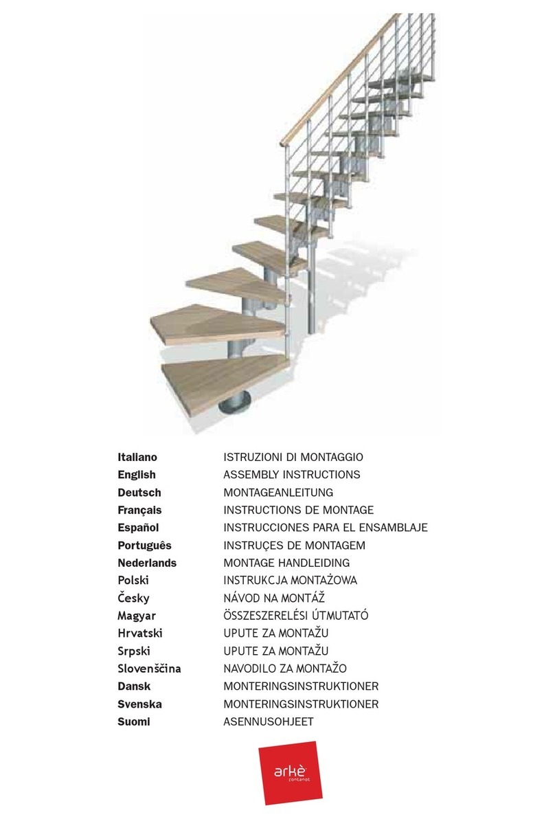
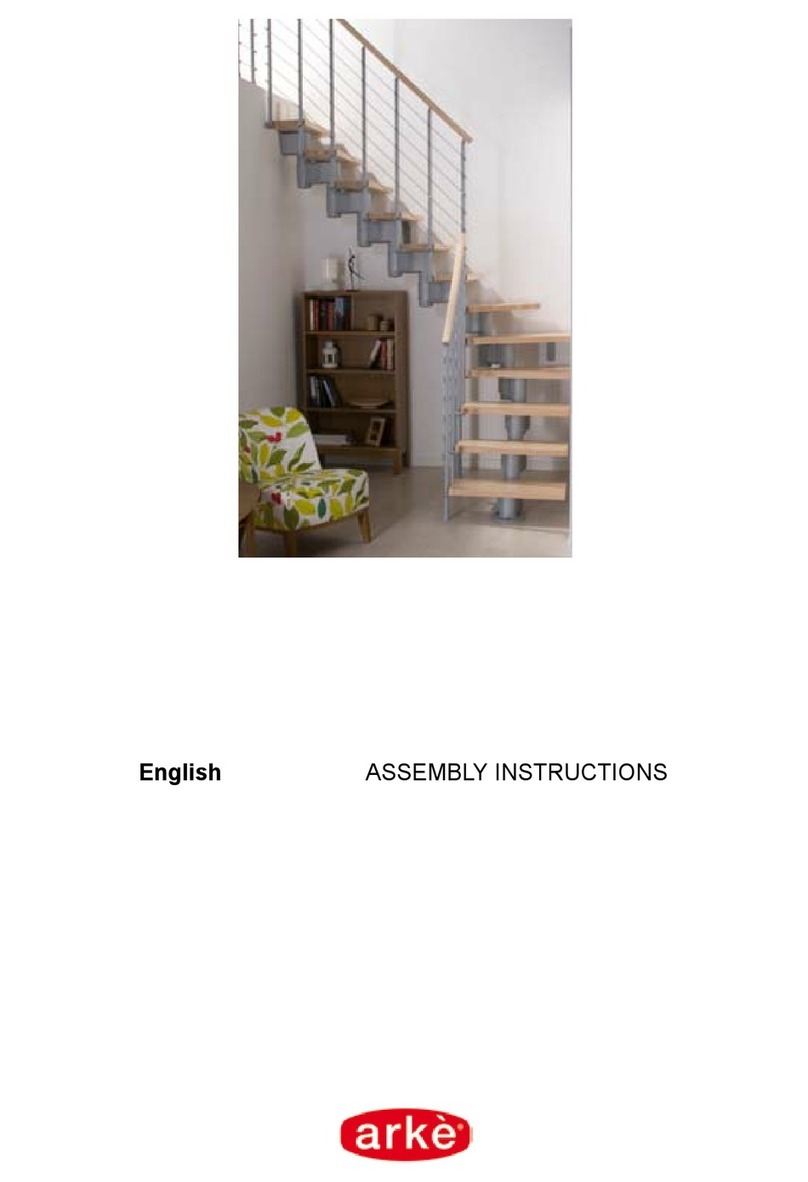
Arke 5199 User manual

English ASSEMBLY INSTRUCTIONS


3 - ko

4 - ko
English
Before starting the assembly, unpack all the pieces of the staircase. Spread them out on a spacious surface and
check the number of pieces (TAB. 1; (A = Code, B = Quantity).
Included in the kit, you will nd a DVD, which you are advised to watch before beginning.
For customers in the USA there is a customer assistance number 1-888 STAIRKT which you can telephone in case
of problems.
Preliminary assembly
1. Assemble the D48 components on the steps (L03) (g. 2).
2. Carefully measure the height from oor to oor so as to work out the number of spacing discs
(D08) and position them above the spacers (D15) (TAB. 2).
3. Assemble components C69, C77, D43,C79,C65 and C74 to the balusters C67, components C69, C77 to
column C73, and nally components C69, C77, D43, C79, C65 to the balusters C68 (g. 3) (g. 1).
4. Assemble the base G03, B17 and B46 (g. 1).
Assembly
5. Determine the centre of the hole to be made in the oor and position the base (G03+B17+B46) (g. 4).
6. Drill the hole with a Ø 14 bit and x the base (G03+B17+B46) to the oor using components B13 (g. 1).
7. Screw the tube (G02) to the base (G03+B17+B46) (g. 1).
8. Insert the base cover (D12) into the tube (G02) (g. 5).
9. Insert, in order, the spacing discs (D08), the shortest spacer (D14), the spacing discs (D08), the rst step (L03),
the spacing discs (D08), the spacer (D15), the spacing discs (D08) and once again the step (L03), and so on.
Position the steps alternately to the left and to the right, so as to distribute the weight uniformly (g. 5).
10. One the end of the tube (G02) is reached, screw on component B47, screw on the next tube (G02) and
continue to assemble the staircase (g. 5).
11. Once the end of the tube (G02) is reached, screw on components B46 and G01 (screw on component G01,
keeping in mind that it must exceed the height of the staircase by about 15 cm (6”) (g. 6). Continue to add the
steps using component D01 inserted into the step (L03).
12. Lastly, insert the landing (E02). After having chosen the direction of rotation (g. 7), line up the landing
(E02) with the small hole (which is needed for the passage of the baluster (C67)) on the arrival side of the steps
(L03) (g.8). Consider the dimensions of the aperture in the upper oor and, if necessary, cut the landing (E02)
accordingly.
13. Insert components B05 and B04 and lock component C70 reasonably tightly, keeping in mind that the steps
must still be turned (g. 1).
Fixing the landing
14. Position component F12 at the aperture in the upper oor. Determine the position and, keeping a distance of
about 15 cm (6”) from the outside edge of the landing (E02), drill a hole using a Ø 14 bit and use B13
components to x it permanently (g. 1).
15. Fix the F12 components to the landing (E02) using the C58 components (drill the landing (E02) with a Ø 5 bit).
16. Position the B95 components.
Assembling the banister
17. Fan out the steps (L03). It is now possible to climb on the staircase.
18. Starting from the landing (E02), insert the longest baluster (C67) to connect the steps (L03).
Orientate the balusters (C67) with the D43 component, which should have the holed part facing
upwards (g. 8). Only tighten the D48 component of the lower step (g. 2).
19. Check that the two columns (C67) which you have positioned are vertical. Pay attention when doing this
because it is very important to the successful assembly of the staircase.
20. Tighten up component C70 (g. 8).
21. Permanently tighten component D48 of the upper step (g. 2).
22. Check again that the balusters (C67) are vertical, and if necessary correct them by repeating the previous
stage.
23. Position the rst baluster (C67). Adjust the height of a long baluster (C67), by cutting off its end, to the height of
those you have just assembled (g. 1).
24. Fix the F34 component to the oor, drilling the hole with an Ø 8 bit, so that it lines up with the rst baluster

5 - ko
(C67). Use components C58, B12, B83 and B02 (g. 1).
25. Identify the handrail sections not marked with the colour red (A13), and those marked with the colour red (A14),
which will be used for the landing (E02) (g. 9).
26. Start to shape the handrails (A13) which are not marked with the colour red, trying to give them a curvature
which follows as closely as possible that of the staircase (g. 1).
27. Starting from the baluster (C67) from the landing (E02), begin to x the handrail (A13) which you have just
shaped. Use the C64 components, with the screwdriver. Warning: position the handrail so that the joining line of
the surface covering is facing downwards.
28. Unite the other handrail segments (A13), screwing them, gluing them (glue X01) and shaping them in
succession. Use components B33 and D35. Orientate the thicker part of item D35 so that it faces outwards.
29. Cut the excess handrail with a hack-saw so that it corresponds with the rst baluster (C67) on the staircase.
30. Complete the handrail (A13), xing component A12 using components C64 and the glue (X01) (g. 1).
31. Insert the steel cables F30 into the items C69 present on the balusters. Lock the cables onto one of the two
ends with items D37 and C76, leaving 5mm of the cable protruding from item D37.Tighten the cables by
hand and lock them with items D37 and C76. Cut off the cable at a distance of 5 mm from item D37. Screw on
components D36, which protect users from the cables. Warning: to cut the cables, we suggest that you use
suitable shears, and that you wrap adhesive tape around the part of the cable to be cut so that it will not
unravel.
32. Check the line of the handrail (A13) and, if necessary, correct it by using a rubber hammer.
33. Complete the assembly of the handrail, inserting components C78 into the side part of the steps (g. 1).
Assembling the balustrade
34. Assemble column (C73) onto component G01, which protrudes from the landing (E02) , orientating items C69
outwards, using components D49 (g. 8) (g. 1).
35. Position components F34, using items C58, B83, B02, on the landing (E02). Drill a hole in the landing (E02)
using a Ø 5 bit and maintaining a distance between the holes which is similar to that between the balusters
(C67) of the banister which you previously assembled.
36. Position the shortest balusters (C68) and tighten items B02 onto components F34 (g. 1).
37. Fix component A15 onto the column (C73) using component B02 (g. 1).
38. Fix the handrail (A14) marked with the colour red, using components C64 (g. 1).
39. Insert the steel cables F30 into the items C69 present on the balusters. Lock the cables onto one of the two
ends with items D37 and C76, leaving 5mm of the cable protruding from item D37. Tighten the cables by
hand and lock them with items D37 and C76. Cut off the cable at a distance of 5 mm from item D37. Screw on
components D36, which protect users from the cables. Warning: to cut the cables, we suggest that you use
suitable shears, and that you wrap adhesive tape around the part of the cable to be cut so that it will not
unravel.
40. According to the position and the existence of walls around the stair-well, it may be necessary to position one or
two extra balusters (C68) (g. 10).
41. In this case it is necessary to consider a space which would be equidistant from the other balusters or from the
walls. To x them, we recommend drilling a hole in the (E02) landing with a Ø 5 bit and using components F34,
C58, B83 and B02, while the oor will need holes drilled with a Ø 14 bit and uses components F34, B02 and
B13 (g. 11). If it is necessary to join the landing banister to the oor banister ( Fig. 10), shape the handrails
carefully, forming curves which match up. If wrinkles should form on the inside of the handrails, it is not a defect.
Rub them energetically (generating heat) with a paper tissue until they go away.
Final Assembly
42. To further strengthen the staircase at intermediate points, x the components F09 to the wall, and join them to
the balusters (C68) using components F33. Drill the holes with an Ø 8 bit and use components C50, C49, C58,
and B12 (g. 12).
We would be grateful, if you could send us any possible suggestion by visiting our Internet Site:
www.arke.ws

6 - ko
A B
Ø120 Ø140 Ø160
A12 3 3 3
A13 5 5 5
A14 1 1 1
A15 2 2 2
B02 15 15 15
B04 1 1 1
B05 1 1 1
B12 710 10
B13 6 6 6
B17 1 1 1
B33 6 6 6
B46 2 2 2
B47 1 1 1
B83 7 7 7
B95 3 3 3
C49 23 3
C50 2 3 3
C54 19 19 19
C58 19 22 22
C64 42 42 42
C67 13 13 13
C68 6 6 6
C69 140 140 140
C70 1 1 1
C73 1 1 1
C74 12 12 12
C76 42 42 42
C77 140 140 140
C78 25 25 25
C79 19 19 19
D01 4 4 4
D08 119 119 119
D12 1 1 1
D14 1 1 1
D15 12 12 12
D35 6 6 6
D36 42 42 42
D37 42 42 42
D43 19 19 19
D48 25 25 25
D49 2 2 2
E02 1 1 1
F09 2 3 3
F12 3 3 3
F30 1 1 1
F33 4 6 6
F34 7 7 7
G01 1 1 1
G02 2 2 2
L03 12 12 12
X01 1 1 1
TAB 1

7 - ko

8 - ko
Italiano
Per determinare la quantità necessaria dei dischi distanziatori (D08) utilizzare la TAB. 2 (H = altezza, A = alzate, X = numero dei dischi distanziatori
(D08) da posizionare sul distanziatore (D15), Y = numero dei dischi distanziatori (D08) da posizionare sul distanziatore (D14)).
Esempio; per un’altezza misurata da pavimento a pavimento di 298 cm (9’ 9 3/8”) e una scala con 13 gradini occorre:
1. In corrispondenza dell’altezza (298 cm (9’ 9 3/8”), nella colonna H), leggere la quantità dei dischi distanziatori necessari (X = 6, Y = 12, nella
colonna A/13).
2. Distribuire i dischi distanziatori (D08), nel modo seguente: 6 dischi distanziatori (D08) su ogni distanziatore (D15) posizionandone 3 sopra e 3
sotto, 12 dischi distanziatori (D08) sull’unico distanziatore (D14), il più corto, posizionandone 3 sopra e 9 sotto.
English
To determine the necessary number of spacers (D08), you must look-up the table TAB.2 (H = Height, A = Rises, X = quantity of spacers (D08) to
position onto the spacer (D15), Y = quantity of the spacers (D08) to position onto the spacer (D14).
Example: given a oor-to-oor height of 298cm (9’ 9 3/8”) and a staircase with 13 treads, you must proceed as follows;
1. At height (298cm (9’ 9 3/8”) in the row H) look-up the number of necessary spacers (X=6, Y=12, in the row A/13).
2. Distribute the spacers (D08), as follows: 6 spacers (D08) onto every spacer (D15) positioning three spacers on the top and three spacers on the
bottom, twelve spacers (D08) onto the only spacer (D14), the shortest one, positioning three on the top and nine on the bottom.
Deutsch
Zur Bestimmung der Anzahl der Distanzringe (D08) die TAB. 2 benützen(H = Höhe, A = Stufenhöhen, X = Anzahl Distanzringe (D08), die in den
Distanzring (D15) gelegt werden müssen, Y = Anzahl Distanzringe (D08), die in den Distanzring (D14) gelegt werden).
Beispiel: für eine abgemessene Fussboden zu Fussbodenhöhe von 298 cm (9’ 9 3/8”) und eine Treppe mit 13 Stufen, wird folgendes benötigt;
1. Bei der Höhenangabe von (298 cm (9’ 9 3/8”), in der Tabelle H), die Anzahl der nötigen Distanzringe ablesen (X = 6, Y = 12, in der Tabelle A/13).
2. Die Distanzringe (D08) so verteilen: 6 Distanzringe (D08) auf jeden Distanzring (D15), in dem 3 oben und 3 unten eingelegt werden, 12
Distanzringe (D08) auf dem einzigen, dem kürzesten, Distanzring (D14), in dem 3 oben und 9 unten eingelegt werden.
Français
An de déterminer la quantité nécessaire des entretoises (D08) employer le TAB. 2 (H = hauteur totale, A = hauteurs, X = numéro des entretoises
(D08) à positionner sur l’entretoise (D15), Y = numéro des entretoises (D08) à positionner sur l’entretoise (D14)).
Exemple; pour une hauteur sol à sol mesurée de 298 cm (9’ 9 3/8”) et un escalier avec 13 marches il faut:
1.Par rapport à la hauteur (298 cm (9’ 9 3/8”), dans la colonne H), lire la quantité des entretoises nécessaires (X = 6, Y = 12, dans la colonne A/13).
2.Distribuer les entretoises (D08), à la manière suivante: 6 entretoises (D08) sur chaque entretoise (D15) en positionnant 3 au-desus et 3 au-
dessous, 12 entretoises (D08) sur l’unique entretoise (D14), la plus courtes, en y positionnant 3 au-dessus et 9 au-dessous.
Español
Para determinar la cantidad necesaria de discos distanciadores (D08) utilizar la TABLA 2 (H =altura, A = tabicas, X = numero de discos
distanciadores (D08) a colocar sobre los distanciadores (D15), Y = numero de discos distanciadores (D08) a colocar sobre el distanciador (D14).
Ejemplo: para una altura de pavimento a pavimento de 298 cm (9’9 3/8”) y una escalera con 13 peldaños es necesario;
1. En la línea de la altura (298 cm (9’ 9 3/8”), en la columna H), leer la cantidad de discos distanciadores necesarios (X = 6, Y = 12, en la columna A/13).
2. Distribuir los discos distanciadores (D08), de la siguiente manera: 6 discos distanciadores (D08) sobre cada distanciador (D15) colocando 3
arriba y 3 abajo, 12 discos distanciadores (D08) sobre el único distanciador (D14), él mas corto, colocar 3 discos arriba y 9 abajo.
Português
Para determinar a quantidade necessária dos discos distanciadores (D08) utilizar a TAB. 2 (H = altura, A = altura do degrau X = número
dos discos distanciadores (D08) a posicionar sobre o distanciador (D15), Y = número dos discos distanciadores (D08) a posicionar sobre o
distanciador (D14)).
Exemplo: para uma altura medida de um pavimento ao outro de 298 cm (9’ 9 3/8”) e uma escada com 13 degraus ocorre;
1. Deacordo com a altura (298 cm (9’ 9 3/8”), na coluna H), ler a quantidade dos discos distanciadores necessários (X = 6, Y = 12, na coluna A/13)
2. Distribuir os discos distanciadores (D08), do seguinte modo: 6 discos distanciadores (D08) em cada distanciador (D15) posicionando 3 em cima
e 3 em baixo, 12 discos distanciadores (D08) em um único distanciador (D14) o mais curto, posicionar 3 em cima e 9 em baixo.
Nederlands
Om het benodigde aantal tussenstukken (D08) te bepalen, met behulp van TAB.2 (H=H=hoogte, A= hoogten, X de nummer van de tussenstukken
(D08) aan de tussenstukken (D15) te leggen. Y = de nummer van de tussenstukken (D08) aan de tussenstukken (D14) te leggen.)
Voorbeeld: voor een hoogte van 298 cm (vloer tot vloer) en een trap van 13 treden, doet men hetvolgende:
1. In functie vande hoogte (298 cm (9' 9 3/8") in de tabel H), leestmen het benodigde aantal tussenstukken af (X = 6, Y = 12, dans la colonne A/13).
2. Men verdeelt de tussenstukken (D08) aan de verschillende manier: 6 tussenstukken (D08) op elke tussenstukken (D15) en leggen men er 3 op
en er 3 onder, 12 tussenstukken (D08) op de enig tussenstukken D14, de meer kort en leggen er 9 onder en er 3 op.
Polski
Aby określić potrzebną ilość krążków odległościowych (D08) należy posłużyć się tabelą TAB. 2 (H = wysokość, A = podstopnie , X = liczba
krążków odległościowych (D08) do umieszczenia na przekładce (D15), Y = ilość krążków odległościowych (D08) do umieszczenia na przekładce
(D14)).
Przykład; przy odległości odmierzonej od posadzki do posadzki równej 298 cm (9’ 9 3/8”) i schodach o 13 stopniach, należy:
1. Dla wysokości (298 cm (9’ 9 3/8”), w kolumnie H), należy odczytać niezbędną ilość krążków odległościowych (X = 6, Y = 12, w kolumnie A/13)
2. Rozmieścić krążki odległościowe (D08), w następujący sposób: po 6 krążków odległościowych (D08) na każdej przekładce (D15) umieszczając
z nich 3 nad i 3 pod, 12 krążków odległościowych (D08) na jedynej, tej najkrótszej przekładce (D14), umieszczając z nich 3 nad i 9 pod.
Česky
Pro určení potřebného množství rozpěrných disků (D08) použijte TAB. 2 (H = výška, A = výšky schodů, X = množství rozpěrných disků (D08) k
umístění na rozpěru (D15), Y = množství rozpěrných disků (D08) k umístění na rozpěru (D14).
Příklad: pro naměřenou výšku od podlahy k podlaze 298 cm (9’ 9 3/8”) a schodiště o 13 schodnicích je třeba:
1. V řádku odpovídajícímu výšce (298 cm (9’ 9 3/8”) ve sloupci H) vyhledejte množství potřebných rozpěrných disků (X = 6, Y = 12,
ve sloupci A/13).
2. Rozmistěte rozpěrné disky (D08) následujícím způsobem: 6 rozpěrných disků (D08) na každou rozpěru (D15), přičemž umisťujte 3 nad a 3
dospodu, 12 rozpěrných disků (D08) na jedinou, nejkratší rozpěru (D14), přičemž umisťujte 3 nad a 9 dospodu.

9 - ko
Magyar
A távtartó korongok (D08) szükséges darabszámának megállapításához használják a 2. TÁBLÁZATOT (H = lépcső magasság, A = lépcsőfokok
száma, X = távtartó korongok száma (D08) amit a D15-ös távtartóra kell helyezni, Y = távtartó korongok száma (D08) amit a D14-es távtartóra kell
helyezni ).
Például: ha a padlószintek között 298 cm van és a lépcsőnek 13 foka van:
1. A magasságnak megfelelően (298 cm, a “H” oszlopban), olvassák le a szükséges távtartó korongok számát ( X = 6, Y = 12 az A/13).
2. A következő módon osszák szét a távtartó korongokat (D08): minden d15-ös távtartóra helyezzenek el 3-at felülre és 3-at alulra, a rövidebb
D14-es távtartóra összesen 12 darabot, 3-at felülre és 9-et alulra.
Hrvatski
Određivanje broja razmaknih elemenata D08 Koristiti TAB. 2 (H = visina gotov pod – gotov pod; A = broj visina (broj gazišta + platforma), X = broj
kom. D08 za postavljanje na element D15; Y = broj kom. D08 za postavljanje na element D14
PRIMJER: Za očitanu visinu gotov pod – gotov pod od 298 cm i 13 visina (12 gazišta + platforma) slijedi:
1. Za visinu 298 cm stupac H i za 13 visina u stupcu A očitavamo količinu razmaknih elemenata X = 6, Y = 12.
2. Raspodijeliti razmakne elemente D08 kako slijedi: 6 kom D08 za svaki D15 postavimo 3 kom. ispod i 3 kom. iznad elementa D15. 12 kom. D08
raspodijelimo za element D14 tako da 3 kom D08 postavimo ispod i 9 kom. iznad elementa D14 (niži element).
Srpski
Određivanje broja razmaknih elemenata D08 Koristiti TAB. 2 (H = visina gotov pod – gotov pod; A = broj visina (broj gazišta + platforma), X = broj
kom. D08 za postavljanje na element D15; Y = broj kom. D08 za postavljanje na element D14
PRIMER: Za očitanu visinu gotov pod – gotov pod od 298 cm i 13 visina (12 gazišta + platforma) sledi:
1. Za visinu 298 cm kolona H i za 13 visina u koloni A očitavamo količinu razmaknih elemenata X = 6, Y = 12.
2. Raspodeliti razmakne elemente D08 kako sledi: 6 kom D08 za svaki D15 postavimo 3 kom. ispod i 3 kom. iznad elementa D15. 12 kom. D08
raspodelimo za element D14 tako da 3 kom D08 postavimo ispod i 9 kom. iznad elementa D14 (niži element).
Slovenščina
Določanje števila razmičnih elementov D08 Glejte tabelo 2 (H = višina med dvema končnima talnima ploskvama; A = število višin (število stopnih
plošč + podest); X = število kosov D08 za postavitev na element D15; Y = število kosov D08 za postavitev na element D14).
PRIMER: Za odčitano višino med dvema končnima talnima ploskvama 298 cm in 13 višinami (12 stopnih plošč + podest) velja:
1. Za višino 289 cm v stolpcu H in za 13 višin v stolpcu A odčitamo količino razmičnih elementov X = 6, Y = 12.
2. Razmične elemente D08 razporedimo na naslednji način: 6 kosov D08 za vsak D15; postavimo 3 kose pod in 3 kose nad element D15. 12
kosov D08 razporedimo za element D14, tako da 3 kose D08 postavimo pod, 9 kosov pa nad element D14 (nižji element)
Dansk
Afstandsskivernes (D08) antal fastsættes ved hjælp af tabellen TAB. 2 (H = højde, A = stigning, X = antal afstandsskiver (D08) som skal placeres
på afstandsstykket (D15), Y = antal afstandsskiver (D08) som skal placeres på afstandsstykket (D14) ).
Eksempel: ved en gulv til gulv højde på 298 cm (9’ 9 3/8”) og en trappe med 13 trin skal man bruge;
1. I henhold til højden (298 cm (9’ 9 3/8”), i kolonnen H), se det nødvendige antal afstandsskiver (X = 6, Y = 12, i kolonnen A/13).
2. Fordel afstandsskiverne (D08) således: 6 afstandsskiver (D08) på hvert afstandsstykke (D15) hvor 3 sættes foroven og 3 forneden, 12
afstandsskiver (D08) på et enkelt afstandsstykke (D14) , det korteste, med 3 foroven og 9 forneden.
Svenska
För att kunna bestämma nödvändigt antal avståndsbrickor (D08) använd TAB.2 (H=höjd, A=steg, X=antal avståndsbrickor (D08) att sätta på
avståndsdel (D15), Y=antal avståndsbrickor (D08) att sätta på avståndsdel (D14).
Exempel: om höjden mätt från golv-till-golv är 298 cm (9’ 9 3/8”) och trappan har 13 trappsteg gäller följande:
1. Se höjden (298 cm (9’ 9 3/8”) i kolumn H), läs nödvändigt antal avståndsbrickor (X=6, Y=12, i kolumn A/13).
2. Distribuera avståndsbrickorna (D08) enligt följande: 6 avståndbrickor (D08) på varje avståndsdel (D15), 3 över och tre under, 12 avståndsbrickor
(D08) på avståndsdel D14, den kortaste, 3 över och 9 under.
Suomi
Jotta voisit saada selville, mikä on välikelevyjen (D08) tarpeellinen määrä, käytä TAULUKKOA 2 (H = korkeus, A = nousut, X =
välikekappaleeseen (D15) asetettava välikelevyjen (D08) määrä , Y = välikekappaleeseen (D14) asetettava välikelevyjen (D08) määrä
Esimerkki: jos korkeus mitattuna lattiasta lattiaan on 298 cm (9’ 9 3/8”) ja portaissa on 13 askelmaa; tulee menetellä seuraavasti:
1. Korkeuden kohdalta (298 cm (9’ 9 3/8”), sarakkeesta H), tulee lukea tarvittava välikelevyjen määrä (X = 6, Y = 12, sarakkeesta A/13).
2. Tämän jälkeen tulee jakaa välikelevyt (D08) seuraavalla tavalla: 6 välikelevyä (D08) kuhunkin välikekappaleeseen (D15) siten että asetat
3 yläpuolelle ja 3 alapuolelle, 12 välikelevyä (D08) yhteen ainoaan välikekappaleeseen (D14), lyhyimpään, siten että asetat 3 yläpuolelle ja
9 alapuolelle.

10 - ko
AAAA
H10 11 H12 13 H14 15 H16 17
XYXY XYXY XYXY XYXY
KIT
210 0 2 253 0 5 296 0 7 338 0 5
211 0 6254 0 8297 0 10 339 09
212 0 9255 0 12 298 1 1 340 0 12
213 1 3 256 1 4 299 1 4 341 11 1
214 1 7 257 1 7 300 1 7 342 1 4
215 2 1258 111 301 111 343 1 7
216 2 4259 2 2 302 2 1 344 1 10
217 2 8260 2 6303 2 4345 1 13
218 32 261 2 10 304 2 8 346 2 2
219 35 262 32 305 2 11 347 2 5
220 3 9 263 35 306 3 1 348 29
221 4 3 264 3 9 307 35349 2 12
222 4 6 265 312 308 3 8 350 2 15
223 5 1266 4 4 309 311 351 3 4
224 5 4267 4 8 310 42 352 3 7
225 5 7268 411 311 4 5 353 310
226 62 269 5 3312 4 8 354 3 13
227 65 270 5 7 313 4 11 355 42
228 6 8 271 5 10 314 5 2 356 45
229 7 3 272 62 315 5 5 357 4 9
230 7 6 273 6 6 316 58358 412
231 7 9 274 6904 317 5 12 0 6359 415 0 4
232 8 4 06275 612 0 8 318 6 209360 5 407
233 8 7 09276 75 0 11 319 6 6 0 12 361 570 10
234 810 0 12 277 7812 320 6912 362 5 10 0 14
235 8 14 1 6 278 711 1 6 321 612 15363 5 12 1 1
236 1 9 279 8419 322 7 3 1 9 364 6 21 4
237 112 280 87112 323 76112 365 651 8
238 2 6281 810 2 4324 7921 366 6 9 1 11
239 2 9282 81327325 712 2 5 367 6 12 1 14
240 2 12 283 2 10 326 8328 368 6 14 2 2
241 3 6 284 32 327 86211 369 7 4 2 5
242 3 9 285 35 328 8931 370 7 7 28
243 312 286 3 8 329 812 3 4 371 7 9 2 12
244 4 6 287 312 330 815 3 7 372 710 2 15
245 4 9 288 4 3 331 3 11 373 7 12 32
246 412 289 4 6 332 3 14 374 8 53 6
247 5 6290 410 333 4 3 375 8 9 3 9
248 5 9291 5 1 334 4 7 376 8 12 312
249 5 12 292 5 4335 410 377 8 15 3 16
250 6 6 293 5 8 336 4 13 378 4 3
251 6 9 294 5 11 337 53 379 4 6
252 612 295 62338 56380 410
253 7 6 296 6 6 339 59 381 4 13
254 7 9 297 6 9 340 5 12 382 5 0
255 712 298 612 341 6 2383 54
256 8 6 299 7 4 342 65384 57
257 8 9 300 7 7 343 6 9 385 5 10
258 812 301 710 344 6 12 386 514
259 302 82 345 7 1 387 6 1
260 303 85346 7 5388 6 4
261 304 8 8 347 7 8 389 6 8
262 305 812 348 7 11 390 611
263 306 8 14 349 8 1 391 6 14
264 307 350 8 4 392 72
265 308 351 8 7 393 7 5
266 309 352 811 394 7 8
267 310 353 8 13 395 712
268 311 354 396 7 15
269 312 355 397 8 2
270 313 356 398 8 6
271 314 357 399 8 9
272 315 358 400 812
273 316 359 401 8 16
TAB 2

11 - ko
H
A
H
A
H
A
H
A
10 11 12 13 14 15 16 17
XYXYXYXYXYXYXYXY
KIT
6' 10 5/8" 0 2 8' 3 5/8" 0 5 9' 8 1/2" 0 711' 11/8" 0 5
6' 11 1/8" 0 6 8' 4 " 0 8 9' 8 7/8" 0 10 11' 11/2" 0 9
6' 11 1/2" 0 9 8' 4 3/8" 0 12 9' 9 3/8" 1 1 11' 17/8" 0 12
6' 11 7/8" 1 3 8' 4 3/4" 1 4 9' 9 3/4" 1 4 11' 2 1/4" 11 1
7' 1/4" 1 7 8' 5 1/8" 1 7 9' 10 1/8" 1 7 11' 2 5/8" 1 4
7' 5/8" 2 1 8' 5 5/8" 111 9' 10 1/2" 111 11' 3"1 7
7' 1 " 2 4 8' 6 " 2 2 9' 10 7/8" 2 111' 33/8" 110
7' 1 3/8" 2 8 8' 6 3/8" 2 6 9' 11 1/4" 2 411' 37/8" 1 13
7' 1 7/8" 328' 6 3/4" 2 10 9' 11 3/4" 2 811' 41/4" 2 2
7' 2 1/4" 358' 7 1/8" 32 10' 1/8" 2 11 11' 45/8" 2 5
7' 2 5/8" 3 9 8' 7 1/2" 35 10' 1/2" 3 1 11' 5 " 2 9
7' 3 "4 3 8' 8 "3 9 10' 7/8" 3511' 5 3/8" 2 12
7' 3 3/8" 4 6 8' 8 3/8" 312 10' 11/4" 3 8 11' 5 3/4" 2 15
7' 3 3/4" 5 1 8' 8 3/4" 4 4 10' 15/8" 311 11' 61/4" 3 4
7' 4 1/4" 5 4 8' 9 1/8" 4 8 10' 2 " 4211' 65/8" 3 7
7' 4 5/8" 5 7 8' 9 1/2" 411 10' 2 1/2" 4511' 7"310
7' 5 " 6 28' 9 7/8" 5 310' 2 7/8" 4 8 11' 73/8" 3 13
7' 5 3/8" 658' 10 1/4" 5 710' 31/4" 411 11' 73/4" 42
7' 5 3/4" 6 8 8' 10 3/4" 5 10 10' 35/8" 5 2 11' 81/8" 45
7' 6 1/8" 73 8' 11 1/8" 62 10' 4" 5 5 11' 81/2" 4 9
7' 6 1/2" 7 6 8' 11 1/2" 6 6 10' 43/8" 5 811' 9"412
7' 7 "7 9 8' 11 7/8" 6 9 0410' 43/4" 5 12 0 611' 93/8" 415 0 4
7' 7 3/8" 8 4 06 9' 1/4" 612 0 810' 5 1/4" 620911' 93/4" 5 407
7' 7 3/4" 8 7 09 9' 5/8" 75 0 11 10' 5 5/8" 660 12 11' 10 1/8" 5 70 10
7' 8 1/8" 810 0 12 9' 1 "7812 10' 6"691211' 10 1/2" 5 10 0 14
7' 8 1/2" 8 14 1 6 9' 1 1/2" 711 1 6 10' 63/8" 612 1511' 10 7/8" 5 12 1 1
7' 8 7/8" 1 9 9' 1 7/8" 8 4 1 9 10' 63/4" 731911' 11 1/4" 621 4
7' 9 1/4" 112 9' 2 1/4" 8 7 1 12 10' 71/8" 76112 11' 11 3/4" 651 8
7' 9 3/4" 2 6 9' 2 5/8" 810 2 410' 71/2" 792112' 1/8" 6 9 1 11
7' 10 1/8" 2 9 9' 3 "8 13 2710' 8"712 2 5 12' 1/2" 612 1 14
7' 10 1/2" 2 12 9' 3 3/8" 2 10 10' 83/8" 832812' 7/8" 6 14 2 2
7' 10 7/8" 3 6 9' 3 7/8" 32 10' 83/4" 86211 12' 11/4" 7 4 2 5
7' 11 1/4" 3 9 9' 4 1/4" 35 10' 91/8" 893112' 15/8" 7 7 28
7' 11 5/8" 312 9' 4 5/8" 3 8 10' 91/2" 812 3 4 12' 2 1/8" 7 9 2 12
8' 1/8" 4 6 9' 5 " 312 10' 97/8" 815 3 7 12' 2 1/2" 710 2 15
8' 1/2" 4 9 9' 5 3/8" 4 3 10' 10 3/8" 311 12' 2 7/8" 712 32
8' 7/8" 412 9' 5 3/4" 4 6 10' 10 3/4" 3 14 12' 31/4" 853 6
8' 1 1/4" 5 6 9' 6 1/8" 410 10' 11 1/8" 4 3 12' 35/8" 8 9 3 9
8' 1 5/8" 5 9 9' 6 5/8" 5 110' 11 1/2" 4 7 12' 4"812 312
8' 2 " 5 12 9' 7 " 5 410' 11 7/8" 410 12' 43/8" 815 3 16
8' 2 3/8" 6 6 9' 7 3/8" 5 811' 1/4" 4 13 12' 47/8" 4 3
8' 2 7/8" 6 9 9' 7 3/4" 5 11 11' 5/8" 5 312' 5 1/4" 4 6
8' 3 1/4" 612 9' 8 1/8" 6211' 11/8" 5 612' 5 5/8" 410
8' 3 5/8" 7 6 9' 8 1/2" 6 6 11' 11/2" 5 912' 6"4 13
8' 4 "7 9 9' 8 7/8" 6 9 11' 17/8" 5 12 12' 63/8" 5 0
8' 4 3/8" 712 9' 9 3/8" 612 11' 2 1/4" 62 12' 63/4" 5 4
8' 4 3/4" 8 6 9' 9 3/4" 7 4 11' 2 5/8" 65 12' 71/8" 5 7
8' 5 1/8" 8 9 9' 10 1/8" 7 7 11' 3"6 9 12' 75/8" 5 10
8' 5 5/8" 812 9' 10 1/2" 710 11' 33/8" 612 12' 8" 5 14
8' 6 "9' 10 7/8" 8211' 37/8" 7 1 12' 83/8" 6 1
8' 6 3/8" 9' 11 1/4" 8511' 41/4" 75 12' 83/4" 6 4
8' 6 3/4" 9' 11 3/4" 8 8 11' 45/8" 7 8 12' 91/8" 6 8
8' 7 1/8" 10' 1/8" 812 11' 5 " 711 12' 91/2" 611
8' 7 1/2" 10' 1/2" 8 14 11' 5 3/8" 8 1 12' 10 " 6 14
8' 8 " 10' 7/8" 11' 5 3/4" 8 4 12' 10 3/8" 72
8' 8 3/8" 10' 11/4" 11' 61/4" 8 7 12' 10 3/4" 75
8' 8 3/4" 10' 15/8" 11' 65/8" 811 12' 11 1/8" 7 8
8' 9 1/8" 10' 2 " 11' 7"8 13 12' 11 1/2" 712
8' 9 1/2" 10' 2 1/2" 11' 73/8" 12' 11 7/8" 715
8' 9 7/8" 10' 2 7/8" 11' 73/4" 13' 1/4" 82
8' 10 1/4" 10' 31/4" 11' 81/8" 13' 3/4" 8 6
8' 10 3/4" 10' 35/8" 11' 81/2" 13' 1 1/8" 8 9
8' 11 1/8" 10' 4"11' 9"13' 1 1/2" 812
8' 12 1/2" 10' 43/8" 11' 93/8" 13' 1 7/8" 8 16
TAB 2

12 - ko
FIG. 1

13 - ko
FIG. 4 FIG. 5
FIG. 6
FIG. 3FIG. 2

14 - ko
FIG. 7

15 - ko
FIG. 8 FIG. 9
FIG. 10 FIG. 11
FIG. 12

16 - ko

Albini & Fontanot S.p.A.
ITALY - 47853 Cerasolo Ausa (Rimini) - Via P.P. Pasolini, 6
Tel. +39 0541 906111 Fax +39 0541 906125
www.arke.ws
D.U.M 01/2008
Table of contents
Other Arke Ladder manuals
Popular Ladder manuals by other brands

Hailo
Hailo 8050 Series Instructions for use

Dolle
Dolle GARDENTOP Trimax Installation instruction

Powerfix Profi
Powerfix Profi PBT-TL012 Assembly, operating and safety instructions

Würth
Würth Scale instructions

Ribimex
Ribimex RIBITECH 20320AP User and maintenance manual

Lippert
Lippert On-the-Go 12.5 Installation and owner's manual