manuals.online logo
Brands
  1. Home
  2. •
  3. Brands
  4. •
  5. Arke
  6. •
  7. Ladder
  8. •
  9. Arke Komoda User manual

Arke Komoda User manual

English ASSEMBLY INSTRUCTIONS
3 - kom
4 - kom
English
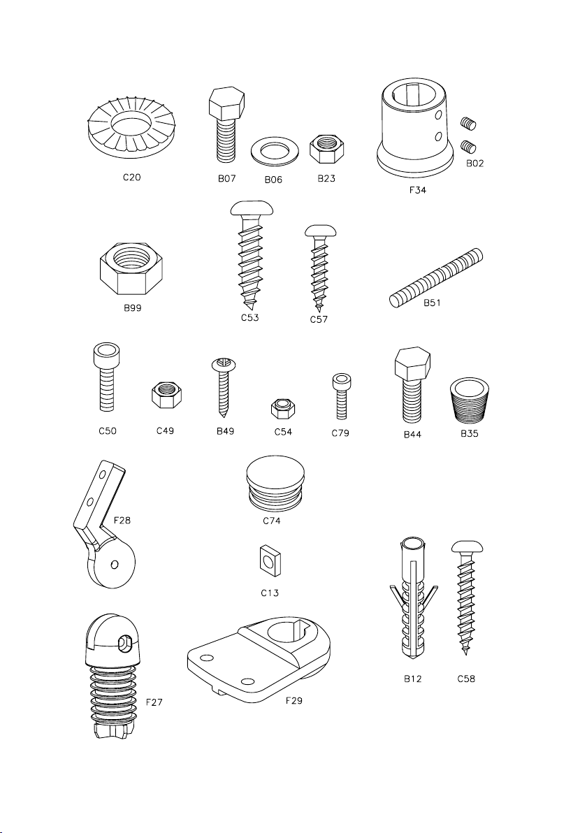
Before starting the assembly, unpack all the pieces of the staircase. Spread them out on a spacious surface and
check the number of pieces (TAB. 1; (A = Code, B = Quantity. For “B” chose the column with the code which you
will nd on the label on the packing case).
Included in the kit, you will nd a DVD, which you are advised to watch before beginning.
For customers in the USA there is a customer assistance number 1-888 STAIRKT which you can telephone in case
of problems.
Assembly
1. Carefully measure the height from oor to oor (H) (g.2).
2. Calculate the value of the riser: a) subtract 20.5 cm (height of the rst riser) from the value you obtained for the
height from oor to oor (H); b) divide this value by the number of risers, less one.
Example: for a height measured from oor to oor of 263 cm and a staircase with 13 risers;
(263 – 20.5 / 13 – 1) = 20.21 cm (g.2).
3. Measure the ceiling aperture (C) carefully (g.2).
4. Calculate the tread value (P):
for the version with going width (railing included) L = 74 (g.2A):
a) subtract from the value found for the ceiling aperture (C) the following xed dimensions:
1) 29 cm = nal tread; 2) 69 cm = corner treads; 3) 1 cm = distance from the wall
b) Divide this value by the number of treads remaining
Example: for a ceiling aperture of 231 cm and a staircase as in (g.2A);
231 – 29 – 69 – 1 / 6 = 22 cm
for the version with tread width (railing included) L = 89 (g.2B):
a) subtract from the value found for the ceiling aperture (C) the following xed dimensions:
1) 33 cm = nal tread; 2) 84 cm = corner treads; 3) 1 cm = distance from the wall.
b) Divide this value by the number of treads remaining.
Example: for a ceiling aperture of 262 cm and a staircase as in (g.2B);
262 – 33 – 84 – 1 / 6 = 24 cm
5. To facilitate the determination of the drilling points, you can mount the tread L25 onto the support N20 using the
screws C53, but without xing it permanently. In this way it will be easy to mark the drilling points which
correspond with the eyelets. Drill the holes with a Ø 18 mm bit (g.4) (g.5). Fix the nal support N20 to the
ceiling aperture with items C48, checking that the staircase is horizontal.
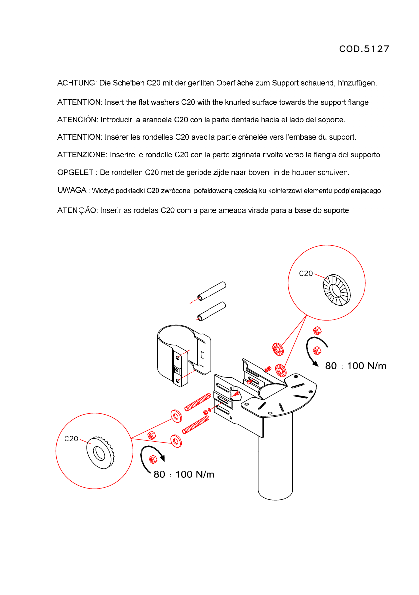
6. Assemble components N24 to supports N21 and N22 (g. 3). Insert the screws B07, B06 and B23 but without
locking them. Insert the tubes C21 in the inside part of parts N24; the braces C22; the washers C20 with the
knurled part facing the ange and the nuts B99. Set in position the tread (P): For the rectilinear treads, the value
(P) is according to the previous calculation (see point 4). For the corner treads, the value (P) is:
20cm (g.2A) for the version with the tread width (railing included) L=74
24cm (g.2B) for the version with the tread width (railing included) L=89
Permanently lock screws B07, B06 and B23. Proceed with the assembly of all of the supports N21. Screw the
tube with the threaded brace N25 to the second support riser N22 as far as it will go.
7. Insert items C13 and B02 into components F29. Fix items F29 using items C57 (on the side where the
railing will be), level with the front edge of the treads L25, upside down (from the holed part), and at a
distance equal to the value of the tread previously calculated (see point 4), except for tread L25 put in place
before the corner treads. Drill with a Ø 4.5 mm bit to a depth of 30 mm.(g.1) (g.7) (g.9).
8. Assemble tread L25 to support N20 with screws C53. Check that the tread is horizontal and permanently x it
with items C48. Apply item D34, to cover the plate, with items B12 and C62, drilling with an Ø 8 mm. bit (g.4)
(g. 5).
9. Insert the intermediate support N21 into the nal support N20. Make it safe at the bottom with self-locking pliers
before xing it permanently. Assemble the tread with screws C53; prop up the supports one by one as you
proceed with the assembly of the structure and of the treads so as to make sure that the weight does not
overload the upper oor. It is essential to insert a prop every 4/5 supports and severely forbidden, for safety
reasons, to climb on the staircase before having xed it to the pavement (point 13) and made it rigid (punto 14).
Place in position the riser as previously calculated (see punto 2); check that it is horizontal and aligned with the
previous tread. Permanently x components B99 working on both sides of the support in order to avoid
changing the trim (horizontal or vertical) of the tread. Warning: check the depth of the tread of tread L25, using
a baluster (C67) going through components F29, making sure that it is perfectly vertical.
Proceed in the same way with the assembly of the remaining intermediate supports N21.
For the corner treads it is necessary to make the support connection holes (N20, N21, N22, N23) according to
the direction of rotation chosen.
5 - kom
Drill the treads (L26, L27, L28) with an Ø 8,5 mm bit to a depth of 30 mm (g.8).
10. Fix component F29 in the inside part of the corner treads L26, L27 and L28 with items C57 (drill with a
Ø 4.5 mm bit to a depth of 30 mm) using a C81 post as a vertical reference. (g.9)
11. Insert the last N22 support (with the two N24 already inserted) into the support N21. Assemble the treads with
the screws C53. Place in position the riser as previously calculated (see point 2). Unscrew component N25 as
far the oor.
Insert support N23 and t it to component N24. Mount the tread. Verify that it is horizontal and aligned with the
previous tread.
12. Check that the staircase is vertical, and if necessary correct it by moving support N23.
13. Remove the rst tread and mark the position of the holes on the oor. Fix it permanently using items B99.
Drill the pavement with a Ø 14 mm bit so that the holes correspond with the holes present in support N23.
Insert the plugs C47 and x permanently (g.1)
14. Stiffen the staircase at the following points:
a) in an intermediate position, insert pole G08 to the oor using items D31, C35 and B20.
b) x the staircase to the wall using component F12 with item B13 (drill with a Ø 14 bit) and screws C57 (drill
with a Ø 4.5 bit) exclusively at the points indicated.
Cover with component B95 (g.15).
Railing Assembly
15. Assemble elements C69, C77, F27, F28,C79, C65 to balusters C67 (g.6) (FIG. 1). Warning: line up the holes
in component F27 with the holes in baluster (C67).
16. Insert connecting balusters C67 between the treads. Orientate the balusters with component F28, with the
holed part facing upwards. Tighten items B02 to item F29.
17. Measure the distance between the three corner treads and cut a C81 baluster to t. Use this segment of
baluster
to connect the three corner treads. Assemble component F29, with items C57, to tread L25 at a distance such
as to permit the mounting of baluster C67 and at a distance from baluster C81 equal to component F25 (Fig.9).
18. Warning: the rst baluster must be cut according to the height of the other balusters. Fix component F34 to the
oor, in correspondence with the rst baluster (C67), drilling with an Ø 8 mm bit. Use items C58, B12 and B02
(g.1).
19. Cut the handrail segments A11 to the correct size (g.10); assemble them with item B51 (g.11). To obtain
a good join, the handrail must make about 1/8 of a turn from the point of contact to the point where the lower
grooving lines up (g.12); if this does not happen, turn the threaded part of the handrail as much as necessary
and screw it with items B44 and B35 (g.13). Fix component A09 with item C43 (g.1).
20. Fix the handrail to the balusters (C67) with items B49; keep the balusters vertical. Cut baluster C67 to the
correct size and assemble it in component F29 with items C57 and B02. Fix component F25 with items C49
and C50. (Fig.14).
21. Insert the steel cables F26 into components C69 present on the balusters. Permanently fasten the cables to
one of the two extremities with items D37 and C76 leaving 5mm of the cable protruding from component D37.
Tighten the cables by hand and lock them with items D37 and C76. Cut off the cables at a distance of 5 mm
from item D37. Screw on cable-protection components D36. Warning: to cut the cables we advise you to use
suitable shears and to wrap the part to be cut with adhesive tape in order to make sure the cable does not
unravel.
22. To stiffen the railing, x the wall baluster with item F09, using items F33. Drill with an Ø 8 bit and use items
C49, C50,C58 and B12 (g.14).
23. Complete the assembly of the handrail, inserting items C74 in the lower part of the balusters (C67) (g.14).
24. Apply items D27,D28 and D29 to close the lower parts (g.1).
25. Apply the items to close the sides D30 in the following way:
1) hook the back part to the pre-curved sheet.
2) bring it into contact with the sheet until the two elastic hooks click into the matching square holes.
We would be grateful, if you could send us any possible suggestion by visiting our Internet Site:
www.arke.ws
6 - kom
A B
K35082 K36031 K35083 K36032
K35088 K36037 K35089 K36038
K35094 K36043 K35095 K36044
K35084 K36033 K35085 K36034
K35090 K36039 K35091 K36040
K35096 K36045 K35097 K36046
A09 6 6
A11 4 3
B02 25 23
B06 22 22
B07 22 22
B12 10 10
B13 2 2
B20 3 3
B23 22 22
B35 1 1
B44 1 1
B49 22 18
B51 4 4
B95 4 4
B99 44 44
C13 21 19
C20 44 44
C21 22 22
C22 22 22
C35 1 1
C43 6 6
C47 3 3
C48 2 2
C49 3 4
C50 3 4
C53 48 48
C54 11 9
C57 44 40
C58 8 8
C62 2 2
C67 11 9
C69 77 63
C74 10 8
C76 28 42
C77 80 65
C79 11 9
C81 1 1
D27 11 11
D28 11 11
D29 11 11
D30 11 11
D31 1 1
D34 1 1
D36 28 42
D37 28 42
F09 2 2
F12 2 2
F25 2 4
F26 1 1
F27 11 9
F28 11 9
F29 21 19
F33 4 4
F34 2 2
G08 1 1
L25 9 6
L26 12
L27 12
L28 12
N20 1 1
N21 9 9
N22 1 1
N23 1 1
N24 11 11
N25 1 1
X01 1 1
TAB 1
7 - kom
8 - kom
FIG. 1
9 - kom
FIG. 2
FIG. 2A
FIG. 2B
10 - kom
FIG. 3
FIG. 4 FIG. 5 FIG. 7
FIG. 6
11 - kom
FIG. 8
12 - kom
FIG. 9
FIG. 10
FIG. 11 FIG. 12 FIG. 13
13 - kom
FIG. 14
14 - kom
FIG. 15
15 - kom
Italiano
KIT RINGHIERA ESTERNA (composta da 4 colonnine, il corrimano e i ssaggi). Nel disegno che segue è possibile contare il numero di colonnine
necessarie, sul lato esterno della scala, considerando la congurazione scelta (le colonnine sono rappresentate dai numeri e dai punti sul lato
esterno).
English
KIT EXTERNAL RAILING (composed of 4 balusters, handrail and xings). From the following drawing it is possible to determine the necessary
number of balusters on the external side of the staircase, taking into account the choosen conguration (the balusters are represented by the
gures and dots visible on the external side)
Deutsch
KIT GELÄNDER AUSSEN-SEITE (bestehend aus 4 Geländerstäben, Handlauf und Befestigungen). In der Zeichnung hierunter kann man die
Anzahl der erforderlichen Geländerstäbe für die Aussenseite zählen, die bei einer Gestaltung dieser Art in Frage kommen. (Die Geländerstäbe
sind auf der Zeichnung mittels der schwarzen Punkte und der Zahlen auf der Aussenseite angegeben).
Français
KIT GARDE-CORPS EXTERIEUR (composé de 4 colonnettes, main-courante et xations). Dans le plan ci-dessous il est possibile de compter le
nombre de colonnettes nécessaires, sur le coté extérieur de l’escalier, en considérant la conguration choisie (les colonnettes sont représentées
par les chiffres et par les points sur le coté extérieur)
Español
KIT BARANDILLA EXTERIOR (compuesto por 4 barrotes, el pasamanos y las jaciones). El siguiente dibujo nos permite saber el número de
barrotes necesarios, en el lado exterior de la escalera, según la conguración elegida (los barrotes están representados por los números y por los
puntos en el lado exterior.
Português
KIT DE GRADE PROTECÇÃO EXTERIOR (composto de 4 colunas, corrimão e xações). No esquema abaixo é possível contar o numero de
colunas necessárias, sobre o lado exterior da escada, considerando a conguração escolhida (as colunas estão representadas pelos algarismos
e pelos pontos no lado exterior).
Nederlands
KIT BUITENBALUSTRADE (bestaande uit 4 spijlen, handgreep en bevestigingsmiddelen) Het plan hieronder maakt het U mogelijk het aantal
spijlen te tellen dat U nodig heeft aan de buitenzijde van de trap, rekeninghoudend met de door U gekozen conguratie. (de spijlen zijn aangeduid
met cijfers en zwarte punten aan de buitenzijde van de trap.)
Polski
BALUSTRADA ZEWNĘTRZNA ( kpl. złożony z 4 tralek, poręczy oraz łączników). N podstawie załączonego rysunku możliwe jest zliczenie ilości
tralek potrzebnych na zewnętrzną stronę schodów, biorąc pod uwagę wybraną kon󰘰gurację ( ilość tralek wyrażona jest liczbami oraz punktami
widocznymi po zewnętrznej stronie schodów )
Česky
SADA PRO MONTÁŽ VNĚJŠÍHO ZÁBRADLÍ (je složena z 4 sloupků, z madla a upevňovacích elementů). Na nákresu, který následuje, je možné
spočítat množství potřebných sloupků, na vnější straně schodiště, budete-li brát v potaz zvolenou kon󰘰guraci (sloupky jsou znázorněny čísly a
tečkami po vnější stranmě).
Magyar
KÜLTÉRI KORLÁT EGYSÉGCSOMAG (összetevők: 4 oszloprúd, korlát karfa és rögzítő elemek). A következő rajz alapján látni lehet az oszlopok
szükséges darabszámát, a lépcső külső felén, a választott modellváltozat alapján (az oszloprudak száma a külső részen van feltüntetve).
Hrvatski
KIT OGRADA S VANJSKE STRANE STEPENICA (Sastoji se od 5 stupića, rukohvata i elemenata za spajanje) Na crtežu koji slijedi moguće je
izbrojiti potrebnu količinu stupića s vanjske strane stepenica, uzimajući u obzir kon󰘰guraciju istih (stupići su označeni brojem i točkicama s vanjske
strane ograde stepenica)
Srpski
KIT OGRADA S SPOLJAŠNJE STRANE STEPENICA Sastoji se od 4 stubića, rukohvata i elemenata za spajanje. Na crtežu koji sledi moguće je
izbrojiti potrebnu količinu stubića sa spoljašnje strane stepenica, uzimajući u obzir kon󰘰guraciju istih (stubići su označeni brojem i tačkicama sa
spoljašnje strane ograde stepenica)
Slovenščina
KIT OGRAJA Z ZUNANJE STRANI STOPNIC (Sestavljena je iz 5 stebričkov, dr`ala in elementov za spajanje) Na naslednji sliki lahko preštejete
potrebno količino stebričev na zunanji strani stopnic, upoštevajoč njihovo kon󰘰guracijo (stebriči so z zunanje strani ograje stopnic označeni s
številkami in pikami).
Dansk
SAMLESÆT UDVENDIGT GELÆNDER (det indholder 4 søjler, håndlisten og kseringer).På den efterfølgende tegning kan man regne det antal
søjler ud, man har brug for til den yderste del af trappen, alt efter den valgte konguration (søjlerne repræsenteres ved de tal og de punkter, som
ndes på den ydersiden).
Svenska
KIT EXTERNT RÄCKE (består av 5 ståndare, handledare och fästen). På teckningen som följer är det möjligt att utläsa antal ståndare som behövs
på den externa sidan av trappan med hänsyn tagen till den valda formen (ståndarna är representerade av nummer och punkter på den externa
sidan).
Suomi
KIT ULKOKAIDE (muodostuu 4:stä tolpasta, käsijohteesta ja kiinnikkeistä). Seuraavasta piirroksesta voitte laskea, mikä on tolppien tarpeellinen
määrä portaiden ulkosivulla, aina sen mukaan, minkä porraskuvion olette valinneet (numerot ja pisteet portaiden ulkosivulla kuvaavat tolppia).
16 - kom
17 - kom
TAB. 2
18 - kom
TAB. 3
19 - kom
TAB. 4
20 - kom
TAB. 5

This manual suits for next models

1

Other Arke Ladder manuals

Arke 5127 User manual

Arke

Arke 5127 User manual

Arke 5199 User manual

Arke

Arke 5199 User manual

Popular Ladder manuals by other brands

FVC SP0207B installation guide

FVC

FVC SP0207B installation guide

GRE AR-116802 installation manual

GRE

GRE AR-116802 installation manual

EZ-ACCESS FORTRESS OSHA Stair System installation manual

EZ-ACCESS

EZ-ACCESS FORTRESS OSHA Stair System installation manual

Vestil ATS-6-56 owner's manual

Vestil

Vestil ATS-6-56 owner's manual

zarges ZAP Safemaster S Assembly and use instructions

zarges

zarges ZAP Safemaster S Assembly and use instructions

Hornbach 58332 owner's manual

Hornbach

Hornbach 58332 owner's manual

KRAUSE 916105 Instructions for assembly and use

KRAUSE

KRAUSE 916105 Instructions for assembly and use

Werner ALDEK Assembly instructions

Werner

Werner ALDEK Assembly instructions

Confer Plastics 635-52 Assembly and instruction manual

Confer Plastics

Confer Plastics 635-52 Assembly and instruction manual

Hard Head 025454 operating instructions

Hard Head

Hard Head 025454 operating instructions

GSi X Series installation manual

GSi

GSi X Series installation manual

pixima fontanot MINI Aassembly Instructions

pixima fontanot

pixima fontanot MINI Aassembly Instructions

GÜNZBURGER STEIGTECHNIK 11153 instruction manual

GÜNZBURGER STEIGTECHNIK

GÜNZBURGER STEIGTECHNIK 11153 instruction manual

Next 594490 Assembly instructions

Next

Next 594490 Assembly instructions

Victor Tools H054 Instructions for use

Victor Tools

Victor Tools H054 Instructions for use

BorMann PRO BHL5710 manual

BorMann

BorMann PRO BHL5710 manual

GIERRE Scalamia AL130 Operating and maintenance instructions

GIERRE

GIERRE Scalamia AL130 Operating and maintenance instructions

Loft Centre Caernarvon 400 Fitting instructions

Loft Centre

Loft Centre Caernarvon 400 Fitting instructions

manuals.online logo
manuals.online logoBrands
  • About & Mission
  • Contact us
  • Privacy Policy
  • Terms and Conditions

Copyright 2025 Manuals.Online. All Rights Reserved.