ARMANNI CP LIGHT evo 030 User manual

FORKLIFT
CP LIGHTevo030.con
PINZA BECCO


Contents
Chapter 1 General information 1-1
1.1 Available documentation ...........................................................................….. 1-1
1.1.1 This handbook..................................................................................….. 1-1
1.2 Information ownership...............................................................................….. 1-1
1.3 Manufacturer's identification data.............................................................….. 1-2
1.4 Machine identification data.......................................................................….. 1-2
1.5 CE conformity statement...........................................................................….. 1-3
1.6 General safety instructions........................................................................….. 1-3
1.6.1 Passive safety devices....................................................................….. 1-4
1.6.2 Active safety devices........................................................................…... 1-4
1.6.3 Personnel qualification.................................................................….. 1-4
1.6.4 Danger zones..................................................................................…. 1-5
1.6.5 Machine danger zones during use and maintenance..............................… 1-5
1.6.6 Personal protections.........................................................................…. 1-6
1.7 Uses foreseen......................................................................................….. 1-6
1.7.1 Operations foreseen.....................................................................…. 1-6
1.7.2 Installation modalities foreseen........................................................….. 1-6
1.7.3 Operation modalities foreseen............................................................…. 1-6
1.7.4 Safety norms and suggestions...........................................................…. 1-7
1.8 Uses not foreseen.....................................................................................….. 1-9
1.9 Guarantee.................................................................................................…... 1-9
1.10 Assistance................................................................................................….. 1-9
1.10.1 Demand for assistance interventions.............................................…. 1-9
1.11 How to use the available documentation................................................….. 1-9
1.11.1 Use of the handbook.......................................................................…. 1-9
1.12 Handbook preservation..........................................................................….. 1-10
1.13 Conventions...............................................................................................….. 1-10
1.13.1 Typographical conventions.............................................................….. 1-10
Chapter 2 Description 2-1
2.1 Machine description..................................................................................…… 2-1
2.1.1 Machine function..........................................................................…… 2-1
2.1.2 Working principle...........................................................................……. 2-1
2.1.3 Structure..........................................................................................…... 2-1
.............................................................................................................…… 2-2
2.2 Properties................................................................................................……. 2-3
2.2.1 Noise.............................................................................................…… 2-3

Contents ARMANNI
2.3 Responsibility...........................................................................................…… 2-3
Chapter 3 Installation 3-1
3.1 Storage.....................................................................................................…... 3-1
3.1.1 Characteristics of the storage area....................................................…. 3-1
3.1.2 Environmental characteristics of the storage area............................…. 3-2
3.2 Transport................................................................................................…… 3-2
3.2.1 Transport conditions........................................................................….. 3-2
3.2.2 Transport.........................................................................................…… 3-2
3.2.3 Lifting.............................................................................................…... 3-2
................................................................................................................…… 3-3
3.2.4 Preliminary operations....................................................................…. 3-3
................................................................................................................…… 3-4
3.3 Collocation..............................................................................................…... 3-4
3.3.1 Physical characteristics of collocation...............................................….. 3-4
.................................................................................................................…… 3-5
3.3.2 Environmental characteristics of the collocation area..........................…. 3-5
3.3.3 Connections.....................................................................................….. 3-5
.................................................................................................................…… 3-6
3.4 Test.........................................................................................................…… 3-7
Chapter 4 Use 4-1
4.1 Operator's qualification............................................................................….. 4-1
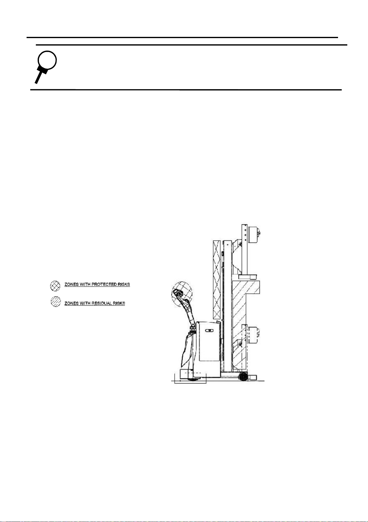
4.2 Danger zones........................................................................................…… 4-1
4.3 Drives and signals.................................................................................……. 4-2
4.3.1 Drives.......................................................................................…… 4-2
.................................................................................................................…… 4-3
4.4 Working....................................................................................................…… 4-3
4.4.1 Machine setting and ignition..................................................….. 4-3
4.4.2 Suggestions for a good piling-up.....................................................….. 4-3
.............................................................................................................…… 4-4
4.4.3 Working modalities...........................................................................…... 4-4
4.5 Working problems..................................................................................…… 4-5
4.5.1 The truck does not move..............................................................…... 4-5
.................................................................................................................…… 4-6
Chapter 5 Maintenance 5-1
5.1 Maintenance obligations in accordance with CE 2006/42 directive.........…. 5-1
5.2 Periodical maintenance checks and technical advice..............................…. 5-2
...........................................................................................................…… 5-3
5.3 Danger zones..........................................................................................…… 5-4
5.4 Routine (periodical and preventive) maintenance.....................................….. 5-4
5.4.1 Operator's qualification......................................................................…. 5-5
5.4.2 Cleaning......................................................................................…… 5-5
5.4.3 Periodical inspections...................................................................…... 5-6
5.4.4 Special maintenance.....................................................................….. 5-7

Contents ARMANNI
Chapter 6 Dismantling 6-1
6.1 Machine deactivation............................................................................…... 6-1
6.2 Deactivation procedures......................................................................…... 6-1
...............................................................................................................……. 6-2
6.3 Risks solved after the machine deactivation......................................…….. 6-3

CHAPTER 1 General information
1.1 Available documentation
1.1.1 This handbook
Handbook data.
- Use and maintenance handbook of the DELTA CP AC-evo Lift Truck
- Edition: 1.0
- Version: 1.0
- January 2013
Consignees.
- Carrier
- Installer
- User
- Maintenance operator
1.2 Information ownership
This handbook contains confidential information. All rights are reserved.
This handbook cannot be reproduced or photocopied, partially or wholly, without the written
authorisation of ARMANNI. The utilisation of this documentation is allowed only to the
customer to whom the handbook has been supplied as a machine equipment, only for
installation, use and maintenance of the machine handbook.
ARMANNI states that all information of this handbook is in compliance with the technical
and safety specifications of the machine handbook. ARMANNI declines all responsibilities
for direct or indirect damages to persons, things or domestic animals due to the use of this
documentation or of the machine in conditions different from the ones suggested.
ARMANNI has the right to change or improve this handbook and ARMANNI machines
without any advance notice, even the machines commercialised with the same nameplate
as the one of this handbook but with a different serial number. The information of this
handbook particularly refers to the machine described in 1.4 "Machine identification data".
1-1

Instruction handbook - General information ARMANNI
1.3 Manufacturer's identification data
ARMANNI CARRELLI ELEVATORI s.r.l.
Via Serio 15
24021 ALBINO (BG)
Tel. +39 035 752909
1.4 Machine identification data
Denomination: LIFT TRUCK
Model: CP LIGHT evo 020 ASPO
Serial number: ..................................................................
Construction year: .............................................................
Possible accessories added: .............................................
For the accessory instruction handbook see enclosures ....
Fig. 1.1 Identification name plate position
1-2
IDENTIFICATION NAME PLATE
POSITION

Instruction handbook - General information ARMANNI
Fig. 1.2 Identification name plate
1.5 CE conformity statement
See enclosure: CE conformity statement
1.6 General safety instructions
During the design and construction of this machine methods and precautions have been
adopted in order to meet the essential safety demands in compliance with the
20069/42/CE Directive and subsequent changes and with applicable norms. In particular,
during the design and construction phases precautionary measures have been adopted
in order to prevent risks for the operators during installation, use, maintenance,
disassemble and deactivation of the machine. The complete documentation of the safety
measures is included in the technical brochure of the machine.
Thanks to the accurate examination of the risks carried out by the manufacturer most
risks in relation to the expected and foreseeable conditions of the machine use have
been eliminated. The possible protections to eliminate completely the fall risk of the load
from the forks would seriously compromise the functionality and versatility of the
machine. Consequently, the residual fall risks of the load from the forks are described in
this manual.
ARMANNI recommends to read carefully the instructions, procedures and suggestions of
this handbook and follow the safety norms in force and the use of the protection
equipment, both those supplemented in the machine and the individual ones.
NOTE ARMANNI declines all responsibilities for possible damages to persons or things due to
the non-observance of the safety norms and recommendations included in the documentation.
1-3

Instruction handbook - General information ARMANNI
1.6.1 Passive safety devices
DEFINITION
Such devices are the devices or precautions that eliminate or reduce the risks for the
operators without any active intervention from the operators.
Microswitch: the presence of the limit switch reduces the movable fork movement at the
maximum height.
Protection grating: it prevents the operator from bringing his hands near to the moving
parts during the load rise and descent.
Bumper on the forks: it prevents the load from falling down on the operator in case of
oscillation.
An important passive safety device is the parachute valve situated in the connection
between the hydraulic plant and the cylinder. In case of a sudden leakage or a break
inside the hydraulic circuit, it locks the load movement in a very short time and avoids
the abrupt descent to the ground.
Rubber foot guard: it prevents the operator's foot from going under the truck.
Safety push-button: in case of contact with the operator, it instantaneously stops the
truck stroke and avoids the squashing.
When the load is lifted at a height of more than 300 mm from the ground, the truck
translation speed is automatically reduced to a lower value by means of a microswitch
positioned near the mast. Also this device serves as a passive safety device.
1.6.2 Active safety devices
Such devices are the devices or precautions that eliminate the risks for exposed
operators or persons or that reduce the risks that can not be eliminated during the
design. Such devices require active and aware interventions from the operator.
The continuous action switches and the lever for the forks lifting/lowering are active
safety devices; in case of international release, they cause the forks movement stop.
The same counts for the onward-backward drives of the truck.
The emergency switch is en active safety device as well since it locks the whole system
when operated in case of danger.
Finally, also the "safety push-button" can serve as an active safety device because it can
be controlled by means of an intentional manoeuvre, too.
1.6.3 Personnel qualification
The machine working is safe when used by qualified personnel in accordance with the
recommendations and instructions of this handbook. All installation, use and
maintenance operations of the machine shall be carried out only by authorised and
qualified personnel after having acquired the instructions supplied by this handbook.
1-4

Instruction handbook - General information ARMANNI
NOTE ARMANNI declines all responsibilities for possible damages to persons, things or
domestic animals due to the use of the machine from unqualified operators.
1.6.4 Danger zones
DEFINITION
A danger zone is any zone inside or near the machine in which the presence of an exposed person
represents a risk for the health and safety for that person.
1.6.5 Danger zones of the machine during use and maintenance
Fig. 1.3 Danger zones of the machine during use and maintenance
1-5

Instruction handbook - General information ARMANNI
DANGER
Each operator shall carry out the operations for which he has been appropriately instructed.
During installation, use and maintenance operations use appropriate means of
personal protection.
The non-utilisation of adequate protection means may be a danger for the operator.
NOTE ARMANNI declines all responsibilities for possible damages to persons or things due to
the non-observance of the safety norms and recommendations included in the
documentation supplied.
1.6.6 Personal protections
The utilisation of protective gloves and safety steel-toed shoes is foreseen for the machine use
1.7 Uses foreseen
1.7.1 Operations foreseen
Drum positioning
Drum lifting
Drum movements
1.7.2 Installation modalities foreseen
The following conditions are necessary for the machine installation:
An environment with sufficient lighting
Flat surfaces without holes
1.7.3 Operation modalities foreseen
The machine is fed by internal electric energy, which is converted into
mechanical, hydraulic and movement energy for the uses foreseen.
One single operator is foreseen for the safe use of the machine.
1-6

Instruction handbook - General information ARMANNI
1.7.4 Safety norms and driving suggestions
In order to use the lift truck safely it is necessary to follow some precautionary norms:
- Only the authorised personnel is allowed to use the truck
- In the work area of the truck there shall be nobody for 8 m. at least, so as to avoid
accidents due to the accidental fall of the load.
- While using it, always keep a correct manoeuvre position.
The load shall have the following dimensions in order to work safely: (See Fig. 1.4):
- As for width, its dimensions shall not project from the load holder grating and have
the barycenter (G) on the longitudinal axis.
- As for length, it shall not exceed a length of 1200 mm and have the barycenter (G)
positioned at a distance lower or equal to the C distance (reported in the technical
specifications) from the load holder grating.
As for height two cases may occur:
1- If the load is not packed, it shall not absolutely project from the load holder grating
2- If the load should project from the load holder grating, the load transport can be
carried out only when it is appropriately packed as one single body with all its parts
(for example, a pallet consisting of a lot of boxes firmly piled up and cellophaned);
In order to reduce the fall risk it will be necessary to keep the load barycenter
lower than the load holder grating.
If you follow these regulations, you will obtain a correct load positioning and a
weight equally distributed on the forks surface, consequently the load balance will
be very stable, thus reducing to a minimum the accident risk due to the accidental
fall of the load.
- All movements inside the firm shall be carried out only along the yellow stripes
on the floor.
- During the movements from one area to the other always keep the forks at a
maximum height of 20 cm from the ground.
- Never overload the truck.
- Center the load on the two forks, so that its barycenter falls on the longitudinal
axis of the truck and the weight is equally distributed on the forks (always refer
to the diagrams of the technical specifications and the label on the mast).
- If the load should hinder the visibility during the movements, carry out a
reverse and go on by keeping the truck behind you.
- Be careful with the piling-up of the material; when starting, avoid abrupt
manoeuvres, stops and steering; Carry out the loading, unloading and
movement operations by keeping the truck motion as straightaway as possible.
- Moderate the speed in the dangerous zones or near obstacles.
- Be careful with slopes, in particular never pass through slopes superior to 5%.
Never pass transversally through slopes. Keep rigorously the forks at a
maximum height of 20 cm from the ground.
- Use the audible alarms if necessary.
- In case of any danger, turn immediately the emergency key anticlockwise.
- Never get near the battery during the recharge with free flames. Read carefully
the use and maintenance handbook of the battery in order to obtain a perfect
efficiency.
- Be careful with fires and explosions, especially in environments where gas
fumes or fuels are present. The truck is not explosion-proof.
- Never leave the truck with hanging loads or with the forks lifted.
If it is unattended, take the key out of the control panel. Park the truck only in
appropriate areas or far from other work areas or working machines (minimum
distance: 5m.).
1-7

Instruction handbook - General information ARMANNI
Fig. 1.4 Load position
Fig. 1.5 Correct attachment
DANGER
The non-observance of the regulations for the load positioning previously mentioned can seriously
increase the fall risk of the load with consequent physical damages to the operator.
1-8

Instruction handbook - General information ARMANNI
1.8 Uses not foreseen
The uses not foreseen are the uses that are not expressly specified in 1.7 Uses foreseen, and
in particular:
The use of the lift truck as an elevator for the rise or descent of persons or for the transport
of persons besides the operator (see version with footboard for operator's transport).
1.9 Guarantee
For the general conditions of guarantee refer to Certification of guarantee, in the 3 Enclosure.
1.10 Assistance
The supplier places at his own clients' disposal an Assistance Service
1.10.1 Demand for assistance interventions
In case of problems during the machine use, it is advisable to read this handbook.
Contact the Assistance Service to solve the problems not mentioned in the handbook or
if the problem persists even after your intervention.
Assistance Service
In case of necessary interventions:
During the guarantee period please contact:
ARMANNI manufacturer
Once the guarantee period is expired, address to:
ARMANNI if the jobber or the assistance centre is unknown.
For spare parts address to:
ARMANNI if the jobber or the assistance centre is unknown.
1.11 How to use the available documentation
1.11.1 Use of the handbook
Before using the machine and carrying out any maintenance operation, read carefully the
conditions given by this handbook.
Table 1.1 How to use the documentation
If you want to: Read
Transport, move, load, unload and operate themachine Chapter 3 Installation
Set and equip the machine Chapter 4 Use
Use the machine already installed and set Chapter 4 Use
Carry out regulations during theuse Chapter 4 Use
Solve the use problems Chapter 4 Use
Estimate and carry out maintenance Chapter 5 Maintenance
Deactivate or dismantle completely the machine Chapter 6 Dismantling 1-9

Instruction handbook - General information ARMANNI
1.12 Handbook preservation
This handbook and the whole documentation shall be preserved for all the technical
duration of the machine. In case of sale of the machine used, the machine shall be sold
along with the documentation supplied.
1.13 Conventions
1.13.1 Typographical conventions
Italics text: it refers to the title of a chapter, a section, a sub-section, a paragraph,
a table or a figure of this handbook or another reference pubblication.
NOTE The notes contain important information, highlighted outside the text they refer to.
ATTENTION
The attention references indicate those procedures whose non or partial observance can cause
damages to the machine or its equipment.
DANGER
The danger references indicate those procedures whose non or partial observance can cause physical
damages to the operator.
1-10

CHAPTER 2 Description
2.1 Machine description
2.1.1 MACHINE FUNCTION
The lift truck is used for lifting and lowering loads and positioning them as desired; or,
once they are lifted from the ground, it is useful for their transport, for short distances
(inside a workshop, warehouse, truck loading/unloading, storage on stands etc.).
2.1.2 WORKING PRINCIPLE
The lift truck moves objects vertically with onward-backward movements or towards a
direction desired by the operator, since he can change both direction and the running
direction by means of the steering wheel.
* Rise
- The high oleodynamic pressure due to a pump connected in series with an
electromotor moves the stem of an hydraulic cylinder, which, fastened to the
basement and pivoted on a support welded to the internal mast, moves it
vertically. Inside the two mast guides, by means of a pulley and chain system,
the movement is transmitted to the forks, in the same translation direction as
the stem.
* Descent
- The force of gravity operates on the forks which drag downward the whole
system moved during the rise. The descent speed is kept constant by the
action of a balancing valve in the gear-case that checks the oil flow from the
cylinder to the tank.
* Movement
- The electromotive force supplied by the motor-wheel gives a motion to the
truck; this motion will be appropriately proportioned and controlled by means
of the drives positioned on the steering wheel. The speed is changed by
means of a potentiometer in the steering wheel, while the movement stop is
controlled by an electromagnetic brake positioned on the same wheel.
* Steering.
- The directional control of the truck is obtained by means of electromechanical
power steering; by rotating the steering arm around its vertical axis, the
operator will control the rotation of the driving wheel around the relevant
steering axis
2.1.3 Structure
The main structural elements of the machine are the following:
Mechanical electro-welded steel structure.
Basement for driving wheel consisting of a closed basement welded .
External mast, pivoted onto the base by means of specific supports .
2-1

Instruction handbook - Description ARMANNI
- Internal mast or headframe sliding inside the external mast.
- The cylinder-stem group
- Traverse cylinder assembly
- The steering wheel group that serves as a steering and manoeuvre point of the
truck.
- The motorwheel.
- The forks group that is integral to the headframe by means of a pulley-chain
connection.
- The sump group.
Electric installation:
- Gearcase of electric installation control including an electronic card protected by a
plastic sump.
- Two fuses
- LED ignition
- hour counter
- LED series which indicate the battery charge condition
- Emergency button to deactivate the electric installation
- 24 V battery
- Motorwheel including:
- Electromotor
- Electrobrake
- Geared motor.
- Steering motor.
- Switches
- A limit switch for the rise
- Switch for the automatic speed reduction
- Key switch for starting
- Emergency button switch
Hydraulic system
- Hydraulic pump
- Tank built-in in the pump
- Hydraulic gearcase:
- 24 V electromotor
- Gearcase lock
- Solenoid valve
- Maximum pressure valve
- Nonreturn valve
- Filter
- Flow adjustment valve to check the oil downflow from the cylinder
- Parachute-type valve to stop the oil flow and the load descent in case of break of
the hydraulic system
- Connectors
- Plastic pipelines
Drive device:
- Rise-descent lever
- Tilting lever
- Electric horn
- Key switch
- Drive devices of onward-backward truck movement
Emergency switch
Safety stop cap
2-2

Instruction handbook - Description ARMANNI
Fig. 2.1 Photograph of the machine
2.2 Properties
2.2.1 Noise
The parameter values of the aerial noise caused by the machine are within the limits in
accordance with the 2006/42/CE European Directive.
The weighted continuous equivalent level A of the acoustic pressure is under 70 dB
(A)
The maximum value of the weighted instantaneous acoustic pressure C is under 63
Pa
2.3 Responsibilities
NOTE ARMANNI declines all responsibilities for possible inconvenience, failures or
malfunctioning due to the non-observance of the feed values supplied.
2-3

CHAPTER 3 Installation
The instructions of this section shall be followed during the periods of temporary storage
of the machine that can occur in the following situations:
Machine installation not immediately after its supply
Machine disassemble and storage awaiting its re-collocation
In case of non-observance of these instructions, ARMANNI declines all responsibilities
for possible damages to the machine or subsequent performance not in compliance with
the technical specifications supplied.
3.1 Storage
3.1.1 Characteristics of the storage area
The machine shall be collocated in a space having the following characteristics:
Dimensions
Besides the overall dimensions of the machine, it is necessary to provide for the
appropriate circulation and manoeuvre spaces so as to allow the personnel to carry out
safely and comfortably the machine sling and lifting.
Protection from environmental and external agents
The storage area shall be covered and protected by the action of the atmospheric
precipitations and is accessible to authorised personnel only.
Supporting plane capacity
The floor shall assure a whole capacity (G) equal to:
P.K . 9,81 Kg . 1,1 . 9,81 m/S²
G = = = .........KN
1000 1000
3-1

Instruction handbook - Installation ARMANNI
Where: G = whole capacity referred to the whole storage area, expressed in (KN)
P = machine weight, expressed in (kg)
K = fixed increased coefficient, in order to include the packaging weight in the
calculation
9,81 = gravity acceleration expressed in (m/S²)
And consequently a unit load (C) equal to:
G . 1000 KN . 1000
C = = = .........N/m²
S m²
Where: C = minimum unit load, expressed in (N/m²)
S = support surface, expressed in (m²)
3.1.2 Environmental characteristics of the storage area
Temperature admitted: from 0° C to 40° C+/-5° C.
Relative humidity admitted: from 30% to 90% +/-5%
3.2 Transport
3.2.1 Transport conditions
The machine shall be transported in the following conditions:
Position the truck with the forks lowered
Cover completely the truck with a plastic covering to protect the machine from
atmospheric agents.
The machine is normally delivered wrapped in a cellophane cloth.
ATTENTION
If there should be particular height problems in the vertical positioning, the truck can be
positioned horizontally on one side (left or right, indifferently) removing the battery and
putting a cap to the oil tank before carrying out the operation.
The bolts and any other material supplied with the machine shall be put into plastic
bags.
Total weight
See technical specifications
3.2.2 Transport
During the transport, the machine shall be correctly covered with cellophane and
fastened to the means of transport so as to avoid movements or turnovers. During
transport operations avoid impacts or turnovers.
3.2.3 Lifting
Lifting equipment
For the lifting of the machine components use:
3-2
Table of contents