Armedica AM Series User manual

This manual has been prepared for the owners and operators
of the ARMEDICA™ AM-Series Hi-Lo Treatment Tables. It
contains installation instructions, precautionary instructions
and maintenance procedures for the following model numbers:
AM-134, AM-140, AM-234, AM-240,
AM-334, AM-340, AM-368
ISO 13485
FM 50089 .

AM-SERIES HI-LO TREATMENT TABLES
Armedica Treatment Tables are intended to be used as physical therapy supports for patients during
clinician attended physical therapy related diagnosis, treatment, and monitoring. The table is
equipped with a vertical table height adjustment actuator and casters for mobile transport.
Patients are not to be left unattended.
INSTALLATION
1. Remove all packaging material from the tables.
2. There is no assembly required on the ARMEDICA™ Treatment Tables.
3. Plug the power cord into a properly grounded 120 Volt AC outlet and follow the
procedure outlined in the Precautionary Instructions.
4. The table is equipped with leveling glides to be used where necessary to achieve
maximum stability.
5. The motor is equipped with a thermal cutout that protects it from overheating.
PRECAUTIONARY INSTRUCTIONS
1. Read, understand and practice the precautionary instructions in this manual. Know the
limitations and the hazards associated with the ARMEDICA™ Treatment Tables.
2. Always disengage the caster system when the table has been placed in
the desired location for patient use.
3. The motor is double insulated for protection from EMI. This equipment has been tested
and found to comply with the limits for medical devices to the IEC 60601-1-2: Third
edition 2007-03. These limits are designed to provide reasonable protection against
harmful interference in a typical medical installation. This equipment generates, uses
and can radiate radio frequency energy and, if not installed and used in accordance with
the instructions, may cause harmful interference to other devices in the vicinity.
However, there is no guarantee that interference will not occur in a particular installation.
If this equipment does cause harmful interference to other devices, which can be
determined by turning the equipment off and on, the user is encouraged to try to correct
the interference by one or more of the following measures:
- Reorient or relocate the receiving device.
- Increase the separation between the equipment.
- Connect the equipment into an outlet on a circuit different from that to which the
other device(s) are connected.
- Consult the manufacturer or field service technician for assistance.
4. For Model 368 and all models with 4-swivel lock casters make certain all casters
are locked prior to patient use.
5. Always use both hands when changing the angle of any section of the
table.
6. Never change the angle of any section when the patient’s weight is on that
section.
7. Never place your hands or feet nor the patient’s hands or feet near any of
the working mechanisms of the table when raising or lowering the table.
8. Never leave the patient unattended.
1

OPERATING INSTRUCTIONS
To adjust the height of the ARMEDICA™ Treatment Tables, a low voltage hand switch or foot
switch is used to activate the electric motor assembly. The up or down motion is clearly
indicated by arrows.
Duty cycle on/off Int. 1 min./ 9 min.
TABLE SECTION ADJUSTMENTS
The sections of the ARMEDICA™ Treatment Tables are raised by lifting them with both hands.
The locking mechanism holds them securely at any angle. To lower a section, hold it in one
hand and release the locking mechanism by turning the knob with the other.
CAUTION: When lowering any of the table sections, make certain that your hands are placed
where they cannot come in contact with the board supports.
CAUTION: When adjusting the sections with the patient on the table, be sure that the patient’s
weight is not on the section you are going to adjust.
CAUTION: To adjust the armrest on the 3-piece head section, use two hands placed on each
end and pull out to the side then raise or lower into the up or down position and release.
CAUTION: Make sure the armrest on the 3-piece head section is locked securely in position
before the patient places any weight on it.
POWER ASSISTED CASTER SYSTEM
To activate the casters, the table must be elevated at least 6 inches above the minimum height.
Pull to slide the caster lever bar toward the foot end of the table and lock into position. Lower
the table to the minimum height. The table is now on casters and can be repositioned. When
the table is in the desired location raise it up 6 inches, lift the lever bar and slide in toward the
head of the table. This will move the activator support bar forward and disengage the caster
system. If the table is not level in its new location, adjust the leveling glides to insure maximum
stability.
MAINTENANCE
The ARMEDICA™ Treatment Tables are equipped with a maintenance free electric motor. The
moving parts of the table should have a drop of oil placed on them approximately every six
months.
Frequently check to make certain that all hardware (nuts, bolts, etc.) are properly adjusted and
securely fastened.
In the event it becomes necessary to replace the hand switch, foot switch or the power cord,
make certain that the plug is in properly and the locking tabs on the motor snaps in place.
The vinyl cover should be cleaned with mild soap and water and the table frame wiped with a
dry cloth to remove dust and lint when necessary.
2

SYMBOLS AND INDICATORS
Attention: Consult accompanying documents.
Type B Equipment: “An adequate degree of protection against electric shock is
provided, particularly regarding leakage currents and reliability of the protective
earth connection.”
The grounding pin located on the power supply cable is for Functional use only,
and is present for EMI/ EMC purposes. The product is Class II equipment and
does not rely on this grounding means for safety.
TROUBLE SHOOTING
MOTOR DOESN’T WORK.
A. Check to see if motor is plugged into receptacle, and the power cord is properly plugged
into the motor.
B. Make sure receptacle is getting power.
C. Check hand switch or foot switch to be sure it is plugged in.
D. Thermal cutout may have activated. Allow the motor to cool.
E. In the event there is a failure of the motor, the motor must be returned to Armedica Mfg.
Corp. The motor must be serviced by the manufacturer.
MOTOR SPECIFICATIONS
500 lbs. CAPACITY: 800 lbs. CAPACITY:
Magnetic Corp., Olney, Illinois 62450 Magnetic Corp., Olney, Illinois 62450
Model MAX 65-A200415A1001-000. Model RUNNER 12KN-RU22-200415A15000-00
Rated Voltage and Frequency 120V 60HZ. Rated Voltage and Frequency 120V 60HZ
Current 1.8 Amps. Current 7 Amps.
UL CORD SET 140-355 POWER SUPPLY MAG BCP-11-RRR-000-000
Duty cycle: on/off Int. 1 min. / 9 min. Duty cycle: on/off Int. 1 min. / 9 min.
Foot switch: IPX1
Transport and storage
Ambient temperature: -20 to 70deg. C
Relative humidity: 10 to 100%, including
Condensation
Atmospheric pressure: 500hPa to 1060hPa
TABLE LIFTING CAPACITY:
AM-134, 140, 234, 240, 334, 340 : AM-368:
500 lbs (226 Kilograms) 800 lbs. (361 Kilograms)
3

PARTS LIST QUANTITYITEM
NO. PART
NO. DESCRIPTION 134 140 234 240 334 340 368
1 18174 BASE FRAME 28” WIDE 1 1 1 1
2 18178 BASE FRAME 36” WIDE 1 1
3 03105 MOTOR MAX65 8000N 120V 1 1 1 1 1 1
4 03107 POWER CORD 1 1 1 1 1 1
5 03106 FOOT SWITCH MAX65 8000N 1 1 1 1 1 1
6 03113 HAND SWITCH MAX65 (OPTIONAL) 1 1 1 1 1 1 1
7 18277 LIFTING ARM HEAD END 1 1 1 1 1 1
8 18330 LIFTING ARM FOOT END 1 1 1 1 1 1
9 18184 CONTROL ROD 3 PC 1 1 1 1 1 1
10 03020 PLUG 1-1/2x2-1/2 6 6 6 6 6 6
11 02010 BOLT SHOULDER 5/16x1-1/2 2 2 2 2
12 02160 WASHER NYLON 5/16ID 4 4 10 10 6
13 03055 WHEEL 2x7/8 2 2 2 2 2 2
14 02100 NUT NYLOCK 1/4-20 2 2 4 4 6 6 4
15 03015 PLUG 1x2 6 6 10 10 10 10 8
16 03010 PLUG 1x1 2 2 2 2 2 2 2
17 03050 CASTER SWIVEL 1 1 1 1 1 1
18 03060 GLIDE LEVELER BASE 2 2 2 2 2 2
19 13098 BUMPER CASTER YOKE 1 1 1 1 1 1
20 18123 CASTER YOKE BRACKET 1 1 1 1 1 1
21 12006 BAR 1/4x3/4x8-5/8 CASTER LOCK LEVER 1 1 1 1 1 1
22 02025 BOLT SHOULDER M 12x50 2 2 2 2 2 2 2
23 02015 BOLT SHOULDER 1/2x1/2 10 10 10 10 10 10
24 02165 WASHER NYLON 1/2 ID 12 12 12 12 12 12 2
25 02020 BOLT SHOULDER 1/2x2 2 2 2 2 2 2
26 02115 NUT NYLOCK M10-1.5 2 2 2 2 2 2 2
27 02049 SCREW HEX HEAD CAP 3/8-16x3 1 1 1 1 1 1
28 18121 CASTER PIVOT BRACKET 1 1 1 1 1 1
29 02145 WASHER 1/2 1 1 1 1 1 1
30 02090 NUT NYLOCK 1/2-13 1 1 1 1 1 1
31 02060 SCREW FLAT HEAD PHIL 1/4-20x1/2 2 2 2 2 2 2
32 02022 BOLT SHOULDER 5/8x1/2 2
33 02110 NUT NYLOCK 3/8-16 3 3 3 3 3 3 2
34 02120 NUT HEX FIN 1/4-20 1 1 1 1 2 2
35 02105 NUT NYLOCK 5/16-18 3 3 7 7 4
36 14078 UPHOLSTERED ADJUSTABLE BOARD 34” 1
37 14072 UPHOLSTERED ADJUSTABLE BOARD 40” 1
38 14080 UPHOLSTERED FIXED BOARD 34” 1
39 14073 UPHOLSTERED FIXED BOARD 40” 1
40 18427 234 FRAME BACK SECTION 1
41 18349 240 FRAME BACK SECTION 1
42 18265 234 TOP FRAME 1
43 18233 240 TOP FRAME 1
44 18452 ROD 1/2x18 FOOT SUPPORT 2 2 2 2
45 18127 BRACKET LOCK SUPPORT 2 2 4 4 4
46 13023 THREADED ROD 1/2x28-1/2 26W 1 1
47 13038 THREADED ROD 1/2x36-1/2 34W 1 1 1
48 02170 PIN SPRING 3/16x1 4 4 6 6
50 03070 KNOB WING 1/2x13ID 2 2 4 4 2
51 03025 SPRING TORSION RIGHT 1 1 1 1 1
52 03035 SPRING TORSION LEFT 1 1 1 1 1
53 02521 BOLT SHOULDER 1/2x2-1/4 2
54 03118 FOOT SWITCH RUNNER BCU CONTROL 1
55 02533 BOLT SHOULDER 5/8x5/8 6
56 03065 GLIDE 1/4-20x1 2 2 2 2 2 2 2

PARTS LIST QUANTITYITEM
NO. PART
NO. DESCRIPTION 134 140 234 240 334 340 368
57 02065 SCREW HEX WASHER HEAD #14x1 13 13 12 12 12
59 02045 SCREW HEX HEAD CAP 1/4-20x1 3 3 4 4 4
60 18489 BASE FRAME 368 1
61 02005 BOLT SHOULDER 5/16-3/4 2 2 4 6 2
62 02035 SCREW BUTTON HEAD SOC 5/16-18x1-1/2 2 2 4 4 4
63 18328 TOP FRAME 334 1
64 18347 TOP FRAME 340 1
65 18172 334 FRAME HEAD SECTION 1
66 18187 340 FRAME HEAD SECTION 1
67 18349 334 FRAME FOOT SECTION 1
68 18427 340 FRAME FOOT SECTION 1
69 14331 334 UPHOLSTERED BOARD HEAD SEC 34” 1
70 14341 340 UPHOLSTERED BOARD HEAD SEC 40” 1
71 14332 334 UPHOLSTERED BOARD CENTER SEC 34” 1
72 14342 340 UPHOLSTERED BOARD CENTER SEC 40” 1
73 14333 334 UPHOLSTERED BOARD FOOT SEC 34” 1
74 14343 340 UPHOLSTERED BOARD FOOT SEC 40” 1
75 03030 SPRING TORSION LESS BEND RIGHT 1 1 1
76 03040 SPRING TORSION LESS BEND LEFT 1 1 1
77 13018 ROD 1/2x27 THD'D 26W HD LOC PLTD 1
79 18446 ROD 1/2x11-11/16 HEAD SEC SUPPORT 2 2 2
80 14727 368 UPHOLSTERED BOARD HEAD SEC 36” 1
81 14729 368 UPHOLSTERED BOARD CENTER SEC 36” 1
82 14728 368 UPHOLSTERED BOARD FOOT SEC 36” 1
83 18473 TOP FRAME 368 1
84 18471 368 FRAME FOOT SECTION 1
85 18481 368 FRAME HEAD SECTION 1
86 13032 THREADED ROD 1/2x36-1/2 HEAD SECTION 1
87 02135 NUT HEX FIN JAM 1/2-13 2 2 4 4 4
89 13034 THREADED ROD 1/2x36-1/2 FOOT SECTION 1
90 18483 LIFTING ARM HEAD END 368 1
91 18485 LIFTING ARM FOOT END 368 1
92 03116 MOTOR MAGNETIC RUNNER 12KN 1
93 03117 POWER SUPPLY MAG BCP-11-RRR-000-000 1
94 03051 CASTER SWIVEL W/ BRAKE 4
95 03012 CAP FINISH BLACK BOLT COVER 4
96 02102 SCREW HEX HEAD CAP 1/2-13x1-1/2 4
97 03011 WASHER RHW-207 FINISH CAP 4
98 02095 NUT NYLOCK JAM 1/2-13 4
99 02070 SCREW HEX WASHER HEAD #14x1-3/4 9 9 4
100 02542 SCREW HEX WASHER HEAD #10x1/2 SELF TAP 4
101 02054 SCREW HEX HEAD CAP 1/4-20x1-3/4 2
102 02055 SCREW HEX HEAD CAP 5/16-18x2 2
103 02150 WASHER 5/16 2 2 2 2 2
104 02130 NUT HX FIN 5/16-18 1 1 1 1 1
105 13043 THREADED ROD 1/2x35 HEAD SECTION 1
106 18759 FRAME TOP AM134 PAINTED 1
107 18318 FRAME TOP AM140 PAINTED 1
108 14872 BD UPH 134 TOP 34x76 1
109 14873 BD UPH 140 TOP 40x76 1
110 02167 WASHER NYLON 5/8 ID 8
111 02076 SCREW PAN HD PHIL 6-32x1/2 2
112 12474 BAR 1/8x3x13.75 CTL BX MNT 368 PNTD 1

23
31
8
20
19
14
21
35
17
1
27
18
28
5
3
22
4
26
13
11
15
25
10
7
16
948
2
10
6
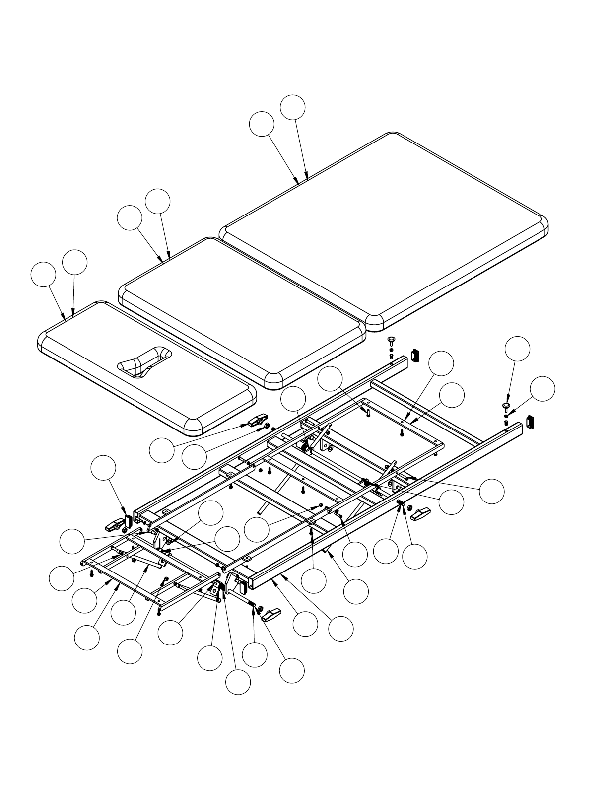
TABLE BASE
AM 234, 240, 334, 340
6

39
87
62
48 35
52
59
56
47 50
51
42
61
41
45
14
12
24
23
15
57
36
37
38
50
43
44
46
ITEM NUMBER 108 IS
USED ON AM-134.
ITEM NUMBER 109 IS
USED ON AM-140
23
24
99
15
106
108
109
107
TOP FRAME
AM 234, 240
TOP FRAME
AM 134, 140
REFER TO MODEL NUMBER COLUMN
ON PARTS LIST FOR ITEMS WITH
TWO REFERENCE NUMBERS.
EXAMPLE:
7
73
34
59
67
56
52
62
51
23
87
63
47
15
61
77
24
75
79
45
48
35
76
65
12
14
50
57
70
72
69
71
74
68
64
66
REFER TO MODEL NUMBER COLUMN ON PARTS LIST
FOR ITEMS WITH TWO REFERENCE NUMBERS.
EXAMPLE: ITEM NUMBER 73 IS USED ON AM-334.
ITEM NUMBER 74 IS USED ON AM-340.
46
44
105
TOP FRAME
AM 334, 340
8

9

81
80
82
85
83
84
78
15
89
15
15
15
79
35
62
88
75
50
14
61
57
99
61
45
35
48
56
50
57
16
16
16
101
99
101
102
87
45
87
86
87
51
52
57
57
62
48
88
76
61
14
12
61
12
14
12
12
104
104
12
105
105
101
T
O
P
F
R
A
M
E
A
M
368
10

PN-03415 REV. E 9/20/11
AM WIDE SERIES
ARMEDICA™ MANUFACTURING CORP.
LIMITED WARRANTY
ARMEDICA™ Manufacturing Corp. warrants that the AM Series treatment tables are free from defects
in material and workmanship. This warranty shall remain in effect for 18 months from the date of original
consumer purchase of the product. If the product fails to function during the warranty period due to a
defect in material or workmanship, ARMEDICA™ Manufacturing Corp. or the selling Dealer will repair
or replace the table without charge within a 30 day period from the date on which the table is returned to
ARMEDICA™ Manufacturing Corp. or the selling Dealer.
THIS WARRANTY DOES NOT COVER
1. Replacement parts or labor furnished by anyone other than ARMEDICA™,
Selling Dealer or approved ARMEDICA™ Service Agent.
2. Any failure of the table during the warranty period if the failure is not caused by a defect in
material or workmanship or if the failure is caused by unreasonable use, including the failure to
provide reasonable and necessary maintenance.
ARMEDICA™ MANUFACTURING CORP. IS NOT LIABLE FOR INCIDENTAL
OR CONSEQUENTIAL DAMAGE TO PROPERTY OR BUSINESS.
To obtain service under this warranty, please do the following:
1. A written claim should be sent to ARMEDICA™ Manufacturing Corp., P.O. Box 880,
Greenwood, AR. 72936-0880 or the selling Dealer.
2. The table must be returned to ARMEDICA™ Manufacturing Corp. or the selling Dealer.
3. This warranty gives you specific legal rights and you may have other rights, which vary from
state to state
ARMEDICA™ does not authorize any person or dealer to create for it any other obligations or liabilities
in connection with the sale of the tables. Any representation or agreement not contained in this warranty
shall be void.
Other manuals for AM Series
2
This manual suits for next models
7
Table of contents
Popular Indoor Furnishing manuals by other brands

nuhoom
nuhoom MANDO 345044 Assembly guide

Costway
Costway JZ10047WH user manual

mopio
mopio Ensley Nightstand Set of 2 Assembly instructions

Tennsco
Tennsco BCD18-72 Assembly Instructions/Parts Manual

hygena
hygena 143/8585 Assembly instructions

Lightolier
Lightolier LYTECASTER REFLECTOR TRIM Instructions for maintenance reference

Festival Depot
Festival Depot PatioFestival quick start guide

Better Homes and Gardens
Better Homes and Gardens Espresso Finish Instruction booklet

GFW
GFW COLORADO 3-DRAWER BED Assembly instructions

Argos
Argos Oslo Oak Table 603/3071 Assembly instructions

SEI
SEI CK7750 Assembly

Axor
Axor Massaud 18020001 Specifications


