Armfield S1 User manual

Drainage and Seepage Tank
Instruction Manual
S1
ISSUE 16
June 2013

ii
Table of Contents
Copyright and Trademarks...................................................................................... 1
General Overview ....................................................................................................... 2
Equipment Diagrams................................................................................................... 4
Important Safety Information....................................................................................... 6
Introduction.............................................................................................................. 6
Electrical Safety....................................................................................................... 6
Water Borne Hazards.............................................................................................. 7
Description.................................................................................................................. 8
Overview.................................................................................................................. 8
Drainage and Seepage Tank................................................................................... 8
Permeable Medium (Sand)...................................................................................... 8
Accessories supplied............................................................................................... 9
Dye Injection Unit .................................................................................................... 9
Permeable Membranes......................................................................................... 10
Impermeable Membranes for Pressure Measurement.......................................... 11
Tile Drain............................................................................................................... 12
Installation................................................................................................................. 13
Advisory................................................................................................................. 13
Electrical Supply.................................................................................................... 13
Installing the Equipment........................................................................................ 14
Commissioning...................................................................................................... 14
Choice of Sand...................................................................................................... 14
Operation .................................................................................................................. 15
Operating the Equipment....................................................................................... 15
Equipment Specifications.......................................................................................... 16
Overall Dimensions ............................................................................................... 16
Equipment Location............................................................................................... 16
Electromagnetic Compatibility............................................................................... 16
Environmental Conditions...................................................................................... 16

Table of Contents
iii
Routine Maintenance................................................................................................ 18
Responsibility ........................................................................................................ 18
General.................................................................................................................. 18
Laboratory Teaching Exercises................................................................................. 19
Index to Exercises................................................................................................. 19
General Comments ............................................................................................... 19
Basic Theory.......................................................................................................... 20
Exercise A - Seepage Underneath a Sheet Pile Wall............................................... 26
Exercise B - Seepage Through an Earth Dam.......................................................... 29
Exercise C - Draining Effect of a Tile Line ................................................................ 31
Exercise D - Draining Effect of an Open Trench....................................................... 33
Exercise E - Uplift Pressure on Foundation of Structures......................................... 34
Exercise F - Changing Uplift Pressure by Changing Length of Flow Lines............... 35
Exercise G - Reduction of Uplift Pressure by Draining ............................................. 36
Exercise H - Reduction of Lateral Thrust on a Retaining Wall by Draining............... 37
Exercise J - Quicksand ............................................................................................. 39
Exercise K - Stability of an Earth Dam...................................................................... 41
Exercise L - Well Draining......................................................................................... 43
Contact Details for Further Information..................................................................... 45


1
Disclaimer
This document and all the information contained within it is proprietary to Armfield
Limited. This document must not be used for any purpose other than that for which it
is supplied and its contents must not be reproduced, modified, adapted, published,
translated or disclosed to any third party, in whole or in part, without the prior written
permission of Armfield Limited.
Should you have any queries or comments, please contact the Armfield Customer
Support helpdesk (Monday to Thursday: 0830 – 1730 and Friday: 0830 - 1300 UK
time). Contact details are as follows:
United Kingdom International
(0) 1425 478781
(calls charged at local rate) +44 (0) 1425 478781
(international rates apply)
Fax: +44 (0) 1425 470916
Copyright and Trademarks
Copyright © 2013 Armfield Limited. All rights reserved.
Any technical documentation made available by Armfield Limited is the copyright
work of Armfield Limited and wholly owned by Armfield Limited.
Brands and product names mentioned in this manual may be trademarks or
registered trademarks of their respective companies and are hereby acknowledged.

2
General Overview
The class of problems involving flow of water through permeable media has a wide
range and is of considerable importance to engineers and scientists. The Armfield
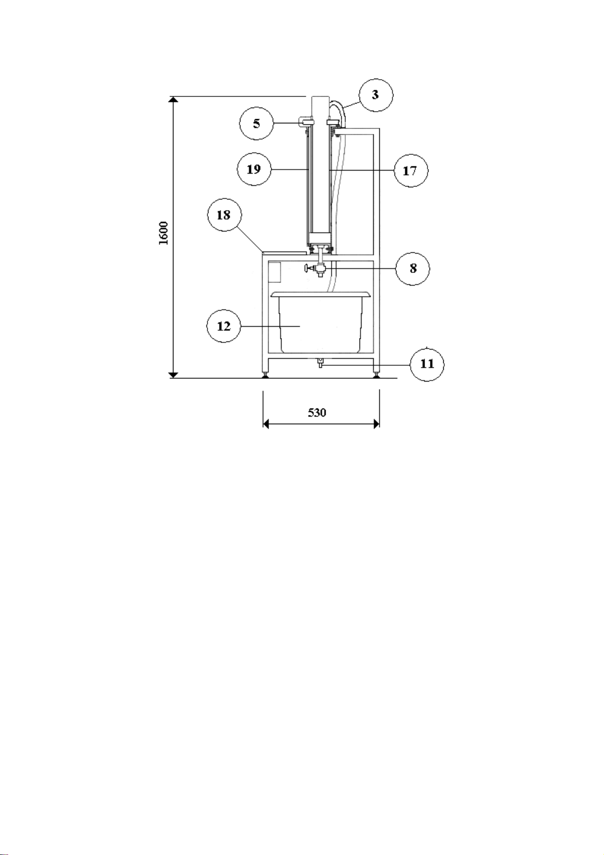
Drainage and Seepage Tank, Model S1, facilitates a detailed study of the movement
of water through permeable media.
The engineer is probably the one who faces such problems most frequently and
whose success or failure will often depend on his knowledge and understanding of
phenomena related to the movement of the water in soils. This is one of the most
important aspects in the design of almost all hydraulic structures. Consider an earth
or rock fill dam, for instance. Water flows directly through the engineering structure
itself. Obviously, it is important to know how much water we can expect to lose from
the reservoir by seepage through the dam. We also need to know whether a certain
kind of soil can be used to construct the dam without running the risk that the
reservoir will run dry after filling. The safety and the very existence of the dam
depends on the flow pattern of the penetrating water and on the balance of the
hydraulic and static forces. Many earth dams have collapsed because of improper
design with respect to the movement of water through their bodies. In fact, the
conditions of seepage are vital, not only for earth dams, but for any dams having
permeable materials in the foundations. A dam can collapse or be badly damaged as
a result of seepage underneath its bottom, or because of hydrostatic forces exerted
by the penetrating waters. These forces cannot be determined without prior
determination of the flow pattern underneath the structure. Once known, they can be
altered using drains, cut-offs, sheet pile walls and other means to change the flow
pattern.
Similar problems arise in other engineering structures built from, or on, soil. As
examples, we can mention levees, road and railway embankments, canals,
navigation locks, foundations of buildings, bridges, harbour walls and similar
structures.
Another engineering field where good understanding of water movement in soil is
essential is water supply and drainage. In both we are concerned with extracting
water from saturated strata by using wells, horizontal galleries, tile lines, or trenches.
In this type of problem, we usually deal only with the flow pattern and quantity of the
water traversing the strata. The forces exerted by seepage remain of secondary
importance.
Mining is an area where both seepage and ground water flow is fundamentally
important. The design of an effective drainage system for a mine must be based on
profound knowledge of permeability, of the degree of water saturation of the various
geological layers, of seepage rates and of the effect of pumping or draining the water
on the balance of forces.
Ground water hydrology and hydrogeology are the main non-engineering fields
dealing with flow of water through permeable media and require the study of
problems such as salt water intrusion into fresh water basins, underground
movement of water towards inner channels, discharge of ground water into surface
run-offs, recharge of water from rivers to underground storage, artificial recharge of
ground water.
Generally speaking, the movement of water through soil under natural conditions is
very complex and cannot be reproduced in full in the laboratory. This complexity is
caused by the non-uniformity of natural soils over large areas, the stratified and the
tectonic structures of geological layers, and by the fact that water movement in

General Overview
3
nature is generally three-dimensional. Such movement is not easy to handle
mathematically.
In the laboratory, we have the advantage of being able to use homogeneous
materials of known properties. This simplifies the problem and makes it possible to
reduce the number of components involved. By this means significant relationships
between the physical properties of the medium and characteristics of flow are found.
To further simplify the problem, we usually restrict ourselves to a two-dimensional
flow, investigating conditions in a vertical cross section* along the horizontal direction
of the moving water mass. The Armfield Drainage and Seepage Tank, Model S1, is
specifically designed to permit the simulation in the laboratory of such vertical cross
sections.
* For obvious practical reasons the cross sections are not planar across sections. But
their thicknesses are small in relation to the height.

4
Equipment Diagrams
Figure 1: Front View of S1 Drainage and Seepage Tank (Shown with impermeable baffle fitted but not filled
with sand)

Equipment Diagrams
5
Figure 2: Side View of S1 Drainage and Seepage Tank

6
Important Safety Information
Introduction
All practical work areas and laboratories should be covered by local safety
regulations which must be followed at all times. If required Armfield can supply a
typical set of standard laboratory safety rules.
Your S1 Drainage and Seepage Tank has been designed to be safe in use, when
installed, operated and maintained in accordance with the instructions in this manual.
As with any piece of sophisticated equipment, dangers may exist if the equipment is
misused, mishandled or badly maintained. If the equipment is used in a manner not
specified by Armfield then the protection provided by the equipment may be
impaired.
The S1 is a heavy piece of equipment, and should be lifted fork lift if possible. Ensure
that the arms of the fork lift do not foul the sump moulding in the base of the unit. Do
not attempt to lift the unit when it is full of sand or water.
Electrical Safety
The equipment described in this Instruction Manual operates from a mains voltage
electrical supply. It must be connected to a supply of the same frequency and voltage
as marked on the equipment or the mains lead. If in doubt, consult a qualified
electrician or contact Armfield.
The equipment must only be connected to a mains supply with a reliable earth
connection so that the equipment is adequately earthed.
The equipment must only be operated using a fused electricity supply. Details of
required fuse ratings can be found on page 10.
The equipment must not be operated with any of the panels removed.
To give increased operator protection, the unit incorporates a Residual Current
Device (RCD), alternatively called an Earth Leakage Circuit Breaker, as an integral
part of this equipment. If through misuse or accident the equipment becomes
electrically dangerous, the RCD will switch off the electrical supply and reduce the
severity of any electric shock received by an operator to a level which, under normal
circumstances, will not cause injury to that person.
At least once each month, check that the RCD is operating correctly by pressing the
TEST button. The circuit breaker MUST trip when the button is pressed. Failure to
trip means that the operator is not protected and the equipment must be checked and
repaired by a competent electrician before it is used.
Accidents can be avoided provided that equipment is regularly maintained and
staff and students are made aware of potential hazards. A list of general safety
rules is included in this manual, to assist staff and students in this regard. The list is
not intended to be fully comprehensive but for guidance only.
Please refer to the following notes regarding the Control of Substances Hazardous to
Health Regulations.

Important Safety Information
7
Water Borne Hazards
The equipment described in this instruction manual involves the use of water, which
under certain conditions can create a health hazard due to infection by harmful
micro-organisms.
For example, the microscopic bacterium called Legionella pneumophila will feed on
any scale, rust, algae or sludge in water and will breed rapidly if the temperature of
water is between 20 and 45°C. Any water containing this bacterium which is sprayed
or splashed creating air-borne droplets can produce a form of pneumonia called
Legionnaires Disease which is potentially fatal.
Legionella is not the only harmful micro-organism which can infect water, but it
serves as a useful example of the need for cleanliness.
Under the COSHH regulations, the following precautions must be observed:
Any water contained within the product must not be allowed to stagnate, ie.
the water must be changed regularly.
Any rust, sludge, scale or algae on which micro-organisms can feed must be
removed regularly, i.e. the equipment must be cleaned regularly.
Where practicable the water should be maintained at a temperature below
20°C. If this is not practicable then the water should be disinfected if it is safe
and appropriate to do so. Note that other hazards may exist in the handling of
biocides used to disinfect the water.
A scheme should be prepared for preventing or controlling the risk
incorporating all of the actions listed above.
Further details on preventing infection are contained in the publication “The Control
of Legionellosis including Legionnaires Disease” - Health and Safety Series booklet
HS (G) 70.

8
Description
Where necessary, refer to the drawings in the Equipment Diagrams section.
Overview
After filling the sand tank with appropriate sand (not supplied) and filling the sump
tank with water the equipment provides a self contained facility for the study of flow
through permeable media. The sand tank has a toughened glass front and the
aluminium back permits the insertion of pressure tappings, tile drains etc.
Drainage and Seepage Tank
A metal frame supports the sand tank (1) above a sump tank (12) and centrifugal
pump (13). The frame has adjustable feet (10) to allow the glass fronted sand tank to
be levelled in both planes. The frame also includes a shelf (18) located in front of and
just below the bottom of the sand tank.
The sand tank is fabricated with an aluminium back panel (17) incorporating six
tapping points (6) and a front panel of toughened glass (19). The tappings in the rear
panel are fitted with sealing plugs that can be removed to incorporate a tile drain
(described in detail later) or used as tapping points, if required.
Two independently adjustable overflows (7 & 16) fitted through the floor, at each end
of the sand tank; allow different water levels to be maintained at each end of the
sand tank to suit different demonstrations. Water is returned to the sump tank by the
overflows. Each overflow incorporates a plug of open cell foam material to prevent
particles of sand from washing into the sump tank.
Two aluminium rails along the top edges of the sand tank provide location for an
adjustable clamp (5) for an impermeable baffle plate (4) or lateral pressure plate
(described later) when required. The rails also allow the position of the clamp (3) for
the water inlet (2) to the sand tank to be varied to suit different demonstrations.
A drain valve (8) in the floor of the sand tank allows water to be drained from the
sand tank after use. Care should be taken to ensure that no sand particles fall into
the sump tank when filling the glass fronted sand tank or making changes during
experiments.
The sump tank can be emptied using the sump tank drain (11).
An electrical switch (15) controls the operation of the pump and hence the supply of
water to the surface of the sand in the sand tank. The flow of water to the sand tank
can be varied using a flow control valve (14) at the pump outlet.
Permeable Medium (Sand)
The equipment supplied does not include the permeable medium (sand) required for
experimental studies. For the Teaching Exercises suggested it is advisable to use a
washed, narrow range sand (coarse sand) with no significant fraction finer than
0.5mm. Alternative sand can be used if required to suit specific requirements.

Description
9
Accessories supplied
The following accessories are supplied for use with S1:
Foundation Pressure Plate
Straight Permeable Membrane (x2)
Curved Permeable Membrane
Lateral Pressure Plate
Tile Drain (x2)
Dye Injection Unit
This consists of a dye reservoir that is mounted on a metal rod clamped to the top rail
of the sand tank as shown below. 6mm internal diameter flexible tubing and 'T'
pieces are used to form four outlets from the dye reservoir, each outlet incorporating
a pinch valve to vary the flow of dye and a hypodermic needle at the end to inject the
dye into the sand. The length of each flexible tube can be varied to locate the
injectors at different positions and different heights in the sand tank to suit particular
demonstrations.

Armfield Instruction Manual
10
Permeable Membranes
Curved Permeable Membrane
Straight Permeable Membrane
Two straight and one curved membrane are supplied with S1. Both membranes are
formed from perforated sheet metal that is covered with fine woven material with
perforations small enough to prevent the passage of sand particles. Rubber strips on
the sides seal the membranes to the vertical front and rear walls of the sand tank.
The ‘V’ shaped straight membrane can be located adjacent to the outlets inside the
sand tank to allow variation of the water depth without the sand affecting the height
adjustment.

Description
11
Impermeable Membranes for Pressure Measurement
Foundation Pressure Plate
Lateral Pressure Plate
Both plates are made of 6mm thick PVC sheet and have rubber sealing strips along
the edges. The foundation pressure plate is 610mm long with 5 Perspex tubes
210mm long normal to the surface, as standpipes. The lateral pressure plate is
720mm long, with longitudinal reinforcement and five standpipes cranked through
90°. Each impermeable plate incorporates filters over the connections to the
standpipes on the inlet face to prevent sand from entering the tubes.

Armfield Instruction Manual
12
Tile Drain
Two tile drain assemblies are supplied for demonstration of dewatering using the tile
drain technique. The tile drains can be used independently or in combination as
required.
Tile Drain
Each drain consists of an 8mm internal diameter copper tube, with one end closed
and having a pattern of eighteen holes drilled along its 150mm length. The open end
is connected to a clean PVC tube 500mm long. Fine woven material is fastened
around the copper tube to act as a filter.
These tile drains can be screwed into any of the six tappings in the aluminium plate
at the rear of the tank, having removed the appropriate sealing plug. Each tapping
incorporates a screwed plug to seal the tapping when no tile drain is fitted.

13
Installation
Advisory
Before operating the equipment, it must be unpacked, assembled and installed as
described in the steps that follow. Safe use of the equipment depends on following
the correct installation procedure.
Electrical Supply
Electrical Supply for Version S1-A
The equipment requires connection to a single phase, fused electrical supply. The
standard electrical supply for this equipment is 230 V, 50 Hz. Check that the voltage
and frequency of the electrical supply agree with the label attached to the supply
cable on the equipment. Connection should be made to the supply cable as follows:
GREEN/YELLOW - EARTH
BROWN - LIVE (HOT)
BLUE - NEUTRAL
Fuse Rating - 1 AMP
Electrical Supply for Version S1-B
The equipment requires connection to a single phase, fused electrical supply. The
standard electrical supply for this equipment is 120 V, 50 Hz. Check that the voltage
and frequency of the electrical supply agree with the label attached to the supply
cable on the equipment. Connection should be made to the supply cable as follows:
GREEN/YELLOW - EARTH
BROWN - LIVE (HOT)
BLUE - NEUTRAL
Fuse Rating - 2 AMP
Electrical Supply for Version S1-G
The equipment requires connection to a single phase, fused electrical supply. The
standard electrical supply for this equipment is 220 V, 60 Hz. Check that the voltage
and frequency of the electrical supply agree with the label attached to the supply
cable on the equipment. Connection should be made to the supply cable as follows:
GREEN/YELLOW - EARTH
BROWN - LIVE (HOT)
BLUE - NEUTRAL
Fuse Rating - 1 AMP

Armfield Instruction Manual
14
Installing the Equipment
This item is supplied as one major assembly, together with all accessories listed
above.
After careful removal from the packing case it should be positioned on a suitable floor
with adequate access space on all sides.
Commissioning
1. Position the equipment as required ensure that the floor is adequate to
support the weight of the equipment when filled with sand and water.
2. Level in the sand tank in both planes by means of the four adjustable feet (10)
on the underside of the frame.
3. Check that the sides of the sand tank are parallel with each other. (It is helpful
for the fitting of the models if the dimensions between the channel sides at the
top slightly exceed that at the base of the channel).
4. Ensure that the tank inlet pipe is located in the clamp (3) at the top of the
sand tank.
5. Check that sump tank drain (11) and sand tank drain (8) are both closed.
6. Fill the sump tank with water.
7. Connect the electrical supply cable to the appropriate mains supply.
Switch on the RCD then press the test button on the RCD. The RCD must
trip. Switch on the RCD again.
8. Close the flow control valve (14) then check the operation of the centrifugal
pump by operating the mains switch. Gradually open the flow control valve
and confirm that water is supplied to the sand tank.
9. Raise both overflow pipes (7 &16) to maximum height and fill the sand tank
with water to check for any leaks. Tighten the clamp strip fixing screws if
necessary.
10. Lower both overflow pipes and drain the water from the sand tank.
11. Check the fit of all models supplied and ensure that all rubber side seals
function correctly (a smear of wetting agent on the seals will aid fitting and
removal).
12. Assemble the dye injection system as shown in Dye Injection Unit in the
Description section. Check the operation of the pinch valve on the flexible
tube connected to each injector needle and water-test the reservoir for leaks.
Having established that all the listed checks are satisfactory, the equipment can now
be fitted with the selected porous medium in preparation for experimental work.
Choice of Sand
It is advisable to use washed, narrow range sand (coarse sand) with no significant
fraction finer than 0.5mm. The sand should be placed in the tank after the tank has
been filled with water to ensure better spreading and mixing.

15
Operation
Operating the Equipment
See the Laboratory Teaching Exercises for details on operating the equipment.

16
Equipment Specifications
Overall Dimensions
Length - 1.60m
Width - 0.60m
Height - 1.45m
Sand Tank Dimensions
Length - 1.50m
Width - 0.10m
Height - 0.60m
Circulating Pump
Duty at 50 Hz: 35 l/min maximum flow
2.2m maximum head
Duty at 60 Hz: 33 l/min maximum flow
3.3m maximum head
Drive: Magnetic coupling
Motor rating: 18 Watts output
Equipment Location
The equipment is designed to stand on level ground capable of carrying the loadings
involved. Access is required all round the assembly.
The equipment requires connection to a 0.1kW single phase, fused electrical supply.
Four metres of supply cable are included with the equipment.
The equipment is a self-contained unit and needs only a temporary supply of cold
water for the initial filling of the sump tank and for cleaning/flushing purposes.
Electromagnetic Compatibility
This apparatus is classified as Education and Training Equipment under the
Electromagnetic Compatibility (Amendment) Regulations 1994. Use of the apparatus
outside the classroom, laboratory or similar such place invalidates conformity with the
protection requirements of the Electromagnetic Compatibility Directive (89/336/EEC)
and could lead to prosecution.
Environmental Conditions
This equipment has been designed for operation in the following environmental
conditions. Operation outside of these conditions may result reduced performance,
damage to the equipment or hazard to the operator.
a. Indoor use;
b. Altitude up to 2000m;
Table of contents
Other Armfield Industrial Equipment manuals
Popular Industrial Equipment manuals by other brands

Lincoln
Lincoln Impinger Aperion 2424E Installation, operation and maintenance manual

Promac
Promac HSL60 Operator's manual

Siemens
Siemens SIWAREX R operating instructions

McElroy
McElroy Hornet XL Series Operator's manual

SMW Autoblok
SMW Autoblok APS Use and maintenance manual

CAB
CAB 4214 Series Assembly instructions