Flowserve 682R User manual

Experience In Motion
682R Reservoir
API 682 Compliant Reservoirs
USER INSTRUCTIONS
Installation
Operation
Maintenance

Flowserve.com 2SSIOM000743-00 (EN/AQ) November 2022
682R Reservoir API 682 Compliant Reservoirs

Flowserve.com 3SSIOM000743-00 (EN/AQ) November 2022
682R Reservoir API 682 Compliant Reservoirs
CONTENTS
1 Introduction 4
1.1 About this manual 4
1.2 How to use this manual 4
1.3 Other supplied documents 4
1.4 Conformity with standards and directives 4
1.5 Use of alerts and icons 5
2 Safety 6
2.1 Types of hazardous exposures 6
2.2 General safety 6
2.3 Trained and qualied personnel 6
2.4 Personal protective equipment (PPE) 7
2.5 Actions in extreme conditions 7
3 Environmental Considerations 8
3.1 Disposing of waste products 8
3.2 End-of-life equipment 8
4 Description 9
4.1 Product purpose 9
4.2 Mechanical seal arrangements 10
4.3 Design features 12
5 Preservation, Packing, Transport and
Storage Requirements 13
5.1 Mechanical preservation instructions 13
5.1.1 Preservation 13
5.1.2 De-preservation 13
5.2 Packing 13
5.3 Transportation and storage requirements 14
6 Installation 15
6.1 Introduction 15
6.2 Safety considerations 15
6.3 Installation requirements 15
6.4 Product set-up 16
6.4.1 Mounting 16
6.4.2 Connections 17
6.4.3 Interconnecting piping 17
6.5 Installation procedure 18
6.6 Transmitter and switch alarm set points 18
7 Operation 19
7.1 Start-up 19
7.2 Product monitoring 19
7.3 Shut down product 20
8 Maintenance 21
8.1 General guidelines 21
8.2 Periodic maintenance tables 21
8.3 Inspection procedure 22
9 Troubleshooting 23
ANNEX I 24
ANNEX II 25

Flowserve.com 4SSIOM000743-00 (EN/AQ) November 2022
682R Reservoir API 682 Compliant Reservoirs
1 Introduction
1.1 About this manual
This manual (which is intended for operating,
maintenance, and supervisory personnel) provides
information on installing, operating, and maintaining the
682R Reservoir.
Installation in accordance with the following instructions
will contribute to long and trouble-free operation of the
assembly.
1.2 How to use this manual
Before using this manual, make sure you have fully read
and understood the safety section, which can be found
in chapter 2. When being new to the 682R Reservoir,
pay attention to section 4, which describes the 682R
Reservoir in detail.
Only trained and qualied personnel should operate the
Reservoir. Refer to section 2.3. Inexperienced personnel
should work on this system under the supervision of
qualied personnel.
When maintaining the Reservoir, always make sure
maintenance procedures are followed. Pay particular
attention to the alerts and icons.
The 682R Reservoir shall be used for as described in this
manual. Discuss with Flowserve if adjustments beyond its
regular use are required.
Changes, modications, repairs or use under conditions
deviating from the design specications without prior
permission of Flowserve can invalidate the product
certication, declaration of conformity and/or nameplate.
NOTE: As hazardous conditions can result from planned
as well as unforeseen circumstances, pressurized
equipment shall always be operated with caution, per site
and local policies.
Before installation, equipment should always be fully
inspected including, but not limited to:
• Any possible damage due to transport or storage
• Cleanliness required before operation
• Existence of an afxed nameplate with correct
inspection markings and design/test conditions
1.3 Other supplied documents
Annex II contains the assembly drawing and sub-
component manuals.
1.4 Conformity with standards and directives
The 682R Reservoir conforms to the following standards
and directives:
• ASME BPVC Section VIII Div. 1
• Pressure Equipment Directive (PED) 2014/68/EU
• Pressure Equipment (Safety) Regulations (PESR) 2016
(UKCA)
• CSA B51
Flowserve.com 5SSIOM000743-00 (EN/AQ) November 2022
682R Reservoir API 682 Compliant Reservoirs
1.5 Use of alerts and icons
This manual uses “Notes”, “Cautions” “Warnings” and
“Dangers” to alert you of important information and/or
hazardous situations.
NOTE: “Notes” inform you of important additional
information.
aCAUTION: The equipment, product or surrounding
area can be damaged if the “caution” is not obeyed.
úWARNING: Personnel can be (seriously) injured,
or the equipment can be seriously damaged if the
“warning” is not obeyed.
c DANGER: Personnel can be (seriously) injured if the
“danger” sign is not obeyed.
The above icons are the general icons that are used for
“Cautions”, “Warnings” and “Dangers”. More specic
icons are also used, depending on the type of hazard. All
Icon used in this manual are listed below:
úWARNING – HIGH PRESSURE: Take caution when
de-pressurizing the 682R Reservoir. The 682R
Reservoir might have energy stored inside. Make
sure that de-pressurizing happens slowly.
úWARNING – HOT SURFACES: The 682R Reservoir
and surrounding surfaces might be hot. Take care
when touching components. Wear the appropriate
Personal Protection Equipment (PPE), according to
plant regulations.
úWARNING – HAZARDOUS CHEMICALS: Dangerous
chemical might be released during removal of
the 682R Reservoir. Wear Personal Protective
Equipment (PPE). Follow all safety regulations and
Plant regulations.
STOP
STOP
STOP
STOP

Flowserve.com 6SSIOM000743-00 (EN/AQ) November 2022
682R Reservoir API 682 Compliant Reservoirs
2 Safety
2.1 Types of hazardous exposures
The following hazards can be present in the system:
• High pressure
• Dangerous or toxic chemicals
• Temperature (hot or cold surfaces)
• Dangerous moving parts (during installation or
maintenance)
• Electrical hazards
If the 682R Reservoir has any external leaks, the process
in which the Reservoir is used should be stopped
immediately and have the leak repaired by qualied
personnel. When extreme conditions occur, and the
possibility of a failure is imminent, plant and end-user
safety regulations shall be followed.
2.2 General safety
When installing, operating and maintaining the 682R
Reservoir, pay attention to safety:
• Obey all applicable safety laws and regulations
• Obey all plant regulations
• Make sure that only trained and qualied personnel
work on it. Refer to section 2.3
• Read and understand each part of this manual
• Follow the installation, operation, and maintenance
procedures
• Wear the relevant personal protective equipment (PPE).
Refer to section 2.4
• Never work alone (to prevent the possibility of an
accident)
• Read the plant requirements for handling hazardous
materials
2.3 Trained and qualified personnel
Qualied personnel are people who have been authorized
by those responsible for the safety of the plant to perform
the necessary work, and who can recognize and avoid
possible dangers. The following aspects determine the
qualication of personnel:
• Appropriate training
• Relevant experience
• Knowledge of relevant standards and specications
• Knowledge of accident prevention regulations
• Knowledge of plant regulations and operating
conditions

Flowserve.com 7SSIOM000743-00 (EN/AQ) November 2022
682R Reservoir API 682 Compliant Reservoirs
2.4 Personal protective equipment (PPE)
The 682R Reservoir is often used for applications
containing high-pressure, high-temperature and/or toxic
chemicals. When performing operating or maintenance
tasks, make sure you wear the appropriate PPE:
protective clothing, gloves, safety glasses, etc.
Always follow local regulations regarding PPE.
2.5 Actions in extreme conditions
In the unlikely event of emergency operating conditions
always follow emergency plant regulations. Immediate
evacuation of service personnel shall follow plant
regulations.

Flowserve.com 8SSIOM000743-00 (EN/AQ) November 2022
682R Reservoir API 682 Compliant Reservoirs
3 Environmental Considerations
aCAUTION: You are required by law to dispose waste
products and end of life equipment, according to
local regulations.
3.1 Disposing of waste products
Make sure waste products are diverted to a safe and
suitable location. Always follow local and plant regulations.
Any waste products resulting from the use or maintenance
of the 682R Reservoir must be recycled or disposed of
according to local environment laws and regulations.
3.2 End-of-life equipment
úWARNING – HAZARDOUS CHEMICALS: Dangerous
chemical might be released during removal of
the 682R Reservoir. Wear Personal Protective
Equipment (PPE). Follow all safety regulations and
Plant regulations.
úWARNING – HIGH PRESSURE: Take caution when
de-pressurizing the 682R Reservoir. The 682R
Reservoir might have energy stored inside. Make
sure that de-pressurizing happens slowly.
úWARNING – HOT SURFACES: The 682R Reservoir
and surrounding surfaces might be hot. Take care
when touching components. Wear the appropriate
PPE, according to plant regulations.
When the equipment reaches the end of life, the
shutdown procedure (section 7.4) shall be followed. The
equipment must then be deinstalled and transported to a
safe location. Always pay extra attention to safety!
NOTE: End-of-life equipment must be disposed of
according to local environment laws and regulations.
STOP
STOP
STOP

Flowserve.com 9SSIOM000743-00 (EN/AQ) November 2022
682R Reservoir API 682 Compliant Reservoirs
4 Description
4.1 Product purpose
The 682R reservoir is used with dual mechanical seal
arrangements (Plan 52, 53A). The purpose of the
Flowserve’s 682R reservoir is to improve the reliability and
extend the life of the dual mechanical seal by providing a
source for clean and cool barrier/buffer uid, remove heat
and control emissions from the mechanical seal.
NOTE: The images of parts shown in these instructions
may differ visually from the actual parts due to
manufacturing processes that do not affect the part
function or quality. Refer to specic product drawing for
connection and dimensional details.
Figure 1: 682R51 Reservoir sectional view
Fill Port
Mounting Bracket (2x)
Product Inlet
Cooling Coil
Product Outlet
Cooling Fluid Outlet
Drain Port
Figure 2: 682R51 external view
Cooling Fluid Outlet
Liquid Level
Indicator
With Tap Plate
Level Switch
Connection
(Plan 52 and 53A)
Level Switch
Connection
Product Inlet
Product Outlet
Vent/Pressurization
Supply, Pressure Gauge
and Pressure Switch
(Plan 52 and 53A)

Flowserve.com 10SSIOM000743-00 (EN/AQ) November 2022
682R Reservoir API 682 Compliant Reservoirs
4.2 Mechanical seal arrangements
The mechanical seal arrangements used for the 682R
reservoir are shown in the following gures with its
corresponding P&ID.
PG: Pressure Gauge
PS: Pressure Switch
LSH: Level Switch High
LSL: Level Switch Low
LG: Level Gauge
PIT: Pressure Indicator Transmitter
LT: Level Transmitter
Per API 682 4th Edition, the reservoir is provided with
transmitters as standard. Switches are available as an
option when specied by the customer.
The P&ID’s on Figures 3 and 4 show the bare reservoir
and optional instrumentation. Refer to the 682R Smart
Drawing for a full list of instrumentation available.
Figure 3: Recommended P&ID piping plan 52
Figure 4: Recommended P&ID piping plan 53A

Flowserve.com 11SSIOM000743-00 (EN/AQ) November 2022
682R Reservoir API 682 Compliant Reservoirs
Piping Plan 52 is an unpressurized dual seal system
which is used in services where no leakage to atmosphere
is tolerated. The system consists of dual mechanical seals
with a buffer uid between the seals. The buffer uid is
contained in the seal pot which is vented to a are, thus
maintaining the buffer uid pressure close to atmosphere.
Primary (inboard) seal leakage will be product leakage into
the buffer uid. There will always be some leakage.
Plan 52 relies on uid circulating from the reservoir to the
mechanical seal. Circulation can come from a circulation
feature in the mechanical seal and/or a thermosyphon
effect with the buffer uid. When a thermosyphon effect
is used, the circulation of liquid occurs due to natural
convention (as opposed to mechanical pumping). The
temperature difference between seal and reservoir will
cause different density across the loop; hence, thermal
expansion.
Warmer liquid will oat about the cooler, moving the buffer
uid upwards, from the seal towards the reservoir.
In a Piping Plan 52 there is an external reservoir providing
buffer liquid for the outer seal of an arrangement 2 seal.
The buffer liquid shall be maintained at a pressure less
than seal chamber pressure and less than 0.28 MPag
(2.8 barg, 40 psig).
Plan 52 works best with clean, non-polymerizing products
which have a vapor pressure higher than the buffer uid
pressure.
These products will ash in the supply tank and the vapor
can escape to the vent system. If the product has a
vapor pressure lower than the buffer uid or supply tank
pressure, the leakage will remain a liquid and will cause
the buffer uid level to rise.
Should excessive primary (inboard) seal leakage not be
detected early, the heavier process uid will displace the
buffer uid and can result in increased seal wear. Used
with dual unpressurized seals, high vapor pressure uids,
light hydrocarbons, hazardous or toxic uids, and heat
transfer uids. Refer to Figure 5 in the following page.
Piping Plan 53A is a pressurized dual seal system
which is used in services where no process leakage to
atmosphere is tolerated. The system consists of dual
mechanical seals with a barrier uid between them. The
barrier uid in the supply tank is pressurized to a higher
pressure than the seal chamber, normally 15 to 25 psig
(1 to 1.7 barg). Primary (inboard) seal leakage will be
barrier uid into the product. A small amount of leakage is
customary.
A Plan 53A is usually chosen over a Plan 52 for dirty,
abrasive or polymerizing products which would either
damage the seal faces or cause problems with the
barrier uid system if a Plan 52 is used. There are two
disadvantages to a Plan 53A which must be considered.
First, there will always be some leakage of barrier uid into
the product. Normally, this leakage will be minute, and
the leakage rate can be monitored via the level gauges
or other instrumentation; however, the product must be
able to accommodate a small amount of contamination
from the barrier uid. Secondly, a Plan 53A system is
dependent on having the supply tank pressure maintained
at the proper level. If the supply tank pressure drops, seal
leakage direction will be reversed (the seal system will
begin to operate like a Piping Plan 52) and the barrier uid
will be contaminated with the process uid.
Used with high vapor pressure uids, light hydrocarbons,
hazardous or toxic uids, heat transfer uids, dirty/
abrasive or polymerizing uids, and mixer or agitators and
vacuum services, refer to Figure 6.

Flowserve.com 12SSIOM000743-00 (EN/AQ) November 2022
682R Reservoir API 682 Compliant Reservoirs
Figure 5: Piping Plan 52 conguration Figure 6: Piping Plan 53A conguration
4.3 Design features
NPT FLANGED CL 600
MAWP 75.5 bar @ 204°C
(1,095 psi @ 400°F)
70.7 bar @ 204°C
(1,025 psi @ 400°F)
MDMT -45.5°C @ 75.5 bar
(-50°F @ 1,095 psi)
-45.5°C @ 70.7 bar
(-50°F @ 1,025 psi)
MIN OPERATING TEMP -40°C
(-40°F)
-40°C
(-40°F)
HYDRO TEST 113.3 bar
(1,643 psi)
106.1 bar
(1,538 psi)
WEIGHT 160 kg
(353 lb)
167 kg
(368 lb)
VOLUME
RESERVOIR (SHELL) 27 liters
(7 gallons)
30 liters
(8 gallons)
RESERVOIR N.L.L. 19 liters
(5 gallons)
19 liters
(5 gallons)
COIL TUBE 0.5 liters
(0.13 gallons)
0.5 liters
(0.13 gallons)

Flowserve.com 13SSIOM000743-00 (EN/AQ) November 2022
682R Reservoir API 682 Compliant Reservoirs
5 Preservation, Packing, Transport and
Storage Requirements
5.1 Mechanical preservation instructions
5.1.1 Preservation
Equipment should not be sealed in a way that it will
obstruct inspection. Access for normal inspection and
preservation maintenance shall be provided. Internal
surfaces of pressure vessels, piping systems and similar
equipment shall be dried and cleaned of surface corrosion
and foreign material.
The 682R Reservoir shall be thoroughly cleaned and dried
after manufacturing and testing, prior to application of
preservatives.
For equipment where water is used for cleaning or
pressure testing, the water shall have antifreeze medium
added unless the water is completely drained off. This
also applies if the ambient temperature is below 4°C
during any of these operations.
Internal surfaces wholly consisting of corrosion resistant
materials shall not be preserved unless stated otherwise.
5.1.2 De-preservation
For de-preservation the applicable dust caps/plugs need
to be removed prior to commissioning. During hook up
it is mandatory to keep these caps/plugs in place for as
long as possible to prevent contamination.
5.2 Packing
úWARNING – CRUSH HAZARD: Possible injury and/
or trapped limbs. Take care to avoid being trapped
or crushed between heavy, moving objects when
(un)boxing the cooler.
The 682R Reservoir shall be lifted carefully with proper
equipment.
Always make sure that proper lifting devices are used.
To prevent damage during transport all equipment needs
to be properly secured inside their package with suitable
bolting, straps or wooden supports.
For unboxing, the equipment must be lifted carefully out of
its shipping box.
STOP

Flowserve.com 14SSIOM000743-00 (EN/AQ) November 2022
682R Reservoir API 682 Compliant Reservoirs
Transport and storage criteria Requirements
Transportation The system must be transported and stored in the unopened, original
shipping box.
Suspect damaged during transportation Carefully inspect equipment that has been dropped or has been subjected to
impacts during transport to confirm that they are operational before installation.
Warehouse requirements The warehouse must be dry and dust free.
Long-term storage After a storage period of 2 years, inspect the 682R Reservoir before installation.
Preserving installed 682R Reservoir Series
The preserving medium prevents damage to the installed system or mechanical
seal (i.e. preventing fouling or chemical attack). Contact Flowserve if you are
unsure which preserving medium to use.
5.3 Transportation and storage requirements
NOTE: The following requirements apply to the 682R
Reservoir and all related equipment:
Table 2 - Transport and Storage Criteria

Flowserve.com 15SSIOM000743-00 (EN/AQ) November 2022
682R Reservoir API 682 Compliant Reservoirs
6 Installation
6.1 Introduction
úWARNING – CRUSH HAZARD: Possible injury and/
or trapped limbs. Take care to avoid being trapped
or crushed between heavy, moving objects when
installing the coolers.
Before installing the 682R Reservoir, make sure you
have read and understood the installation requirements
in this section. If you have any questions regarding the
installation of the 682R Reservoir, contact your local
Flowserve representative.
6.2 Safety considerations
úWARNING – CHECK BEFORE DISASSEMBLING:
Under no circumstances should the 682R Reservoir
be disassembled while it still contains any
hazardous materials or when it is pressurized.
c DANGER – SUFFOCATION HAZARD: Breathing
hazardous chemicals in a confined space can result
in sudden unconsciousness or death. Take extra
care when working in confined areas.
Position the 682R Reservoir as close to your main
equipment as possible. Make sure there is sufcient
room for:
• Evacuation of the plant in case of an emergency (do not
block walkways and emergency exits)
• Safe operation and maintenance of the system
STOP
STOP
6.3 Installation requirements
Before installation the following shall be checked:
• Any possible damage due to transport or storage
• Cleanliness, required before operation
• Existence of the nameplate with correct inspection
markings and design/test conditions

Flowserve.com 16SSIOM000743-00 (EN/AQ) November 2022
682R Reservoir API 682 Compliant Reservoirs
6.4 Product set-up
6.4.1 Mounting
• The optimum mounting height is dened by the
viscosity of the uid, the hydraulic resistance and the
pressure head required for proper ow supply. Consider
the source of the pressure: A pump ring provides a
lower pressure head vs. a recirculation pump.
• Generally, the reservoir shall be mounted such that the
normal liquid level (NLL) is a minimum of 0.9 m (3 ft)
above the seal centerline, and the reservoir centerline
is a maximum of 1.2 m (4 ft) horizontally from the pump
centerline as shown in Figure 7.
• It is highly recommended that the reservoir be ushed
with clean uid prior to equipment start-up to remove
any foreign matter from the system.
• Connect the supply connection (lower seal connection
on the reservoir) to the bottom (inlet) gland connection
(BI - inlet).
• Connect the return connection (upper seal connection
on the reservoir) to the upper (outlet) gland connection
(BO - outlet).
• If the reservoir is equipped with cooling coils, connect
water lines to the coil connections on the bottom of the
reservoir.
• Connect wiring to any instruments included with the
system such as a pressure switch/transmitter or level
switch/transmitter.
• For the liquid level indicator, the bolts on the cover
should be retorqued to 20 ft/lbs. (Tighten in 5 ft/lb.
increments starting with the center bolts and working
out).
In case that a different torque is specied in the liquid
level indicator, it should be followed.
• Connect vent connection to are or vapor recovery
system (Plan 52).
Do not open vent valve until reservoir has been lled
with buffer uid.
• If using oil as a barrier uid (Plan 53A), ll reservoir up to
the middle of the liquid level indicator. Then connect the
external pressurization (gas line).
• If using water as a barrier uid (Plan 53A WM), connect
external pressurization (water supply) to reservoir.
• Maintain a constant pressure on the system. The
pressure should be less than 2.8 bar (40 psi) for a Plan
52 and seal chamber plus 1.4 bar (20 psi) for a plan
53A.
Figure 7: Piping Plan 53A mounting dimensions example

Flowserve.com 17SSIOM000743-00 (EN/AQ) November 2022
682R Reservoir API 682 Compliant Reservoirs
6.4.2 Connections
6.4.2.1.682R Reservoir in a buffer/barrier plan
When the 682R Reservoir is used in a buffer/barrier plan
(plan 52, 53), the top connection shall be connected to
the buffer/barrier outlet connection of the mechanical seal,
while the bottom ange shall be connected to the buffer/
barrier inlet connection of the mechanical seal.
6.4.3 Interconnecting piping
The ow of uid through the 682R Reservoir is either
generated by:
• A pumping device, included in the seal design
• A circulation pump
• Thermosyphoning by natural convection
The interconnecting piping between the 682R Reservoir
and the main equipment must be correctly tted;
otherwise the ow of the uid through the 682R Reservoir
will be restricted and have a negative impact on the
performance.
Pay attention to the following points:
• Minimize the number of restrictions (for example, limit
the number of elbow/tee ttings).
• Unless otherwise specied, the pipe size should be
0.75 in. and schedule shall be the same as the system
piping.
• The pipes must be clean and free of burrs.
• The total pipe length and number of bends shall be
kept to a minimum.
• Use smooth, large radius bends; do not use elbows,
tees, etc.
• Pipe runs should be sloped continuously up or down
to allow for adequate circulation, proper venting and
draining.
• Make sure that the loop, including seal ange, does
not include vapor traps. When vapor traps cannot be
avoided, a proper venting solution shall be added.
• For threaded connections, do not use Teon tape but
an anaerobic thread sealant.
• Leak testing is recommended after assembly. Refer to
end user specications or procedures.

Flowserve.com 18SSIOM000743-00 (EN/AQ) November 2022
682R Reservoir API 682 Compliant Reservoirs
6.5 Installation procedure
Use this procedure to install or reinstall the system.
Procedure
1. Before installing the 682R Reservoir, inspect all
components for damage. If any of the components
are damaged, you should report this to your local
Flowserve representative. Refer to section 6.3.
2. Determine the installed position of the system. Refer to
the mounting requirements, section 6.4.1.
3. The 682R Reservoir shall not be moved by hand.
It is equipped with a lifting lug. Use an appropriate
lifting device to position the 682R Reservoir as close
as possible to the main equipment. Make sure you
leave sufcient room for operation and maintenance
purposes.
úWARNING – CRUSH HAZARD: Possible injury and/
or trapped limbs. Take care to avoid being trapped
or crushed between heavy, moving objects when
installing the cooler
4. Make sure that the 682R Reservoir is installed in a rigid
support to counteract any vibrations and instability.
úWARNING – HIGH PRESSURE: Take caution when
de-pressurizing the 682R Reservoir. The 682R
Reservoir might have energy stored inside. Make
sure that de-pressurizing happens slowly.
5. Connect the 682R Reservoir connections. Refer to
section 6.4.2.
6. Manufacture the interconnecting piping according to
the Installation requirement. Refer to section 6.4.3.
7. Make sure the installation is correctly earthed to
prevent the potential risk of explosion caused by static
electricity.
NOTE: Leak testing is recommended after assembly.
Refer to end user specications or procedures.
6.6. Transmitter and switch alarm set points
• The instrument alarm setting depends on the purpose
of the specic instrument (high alarm for Plan 52 and
low alarm for Plan 53A). A high level switch shall be set
to normally open (not detecting liquid), while a low level
switch shall be set to normally closed (detecting liquid).
• For the Plan 52 the pressure transmitter or pressure
switch shall provide a high-pressure alarm between 0.3
to 2.1 bar (5 to 30 psi). The alarm set point should be
below seal chamber pressure, typically less than
2.1 bar (30 psi).
• For the Plan 53A the pressure transmitter or pressure
switch shall provide a low-pressure alarm between 1.6
to 10.3 bar (24 to 150 psi). The alarm set point should
ensure the reservoir pressure is at least 1.4 bar (20 psi)
higher than seal chamber.
• For additional information on how to install or set alarm
points on the instrumentation, refer to the IOM specic
to the instrument.
STOP
STOP

Flowserve.com 19SSIOM000743-00 (EN/AQ) November 2022
682R Reservoir API 682 Compliant Reservoirs
7 Operation
7.1 Start-up
1. Make sure the 682R Reservoir is installed correctly,
refer to chapter 6.5.
2. Open the interconnecting valving for the system.
3. Make sure commissioning of the system has been
performed properly. Ensure that all the trapped gas/air
is vented from the system and interconnecting piping
and that the system can be completely drained.
4. Start up the pump according end user/plant
procedures.
7.2 Product monitoring
úWARNING – HIGH PRESSURE: Take caution when
de-pressurizing the 682R Reservoir. The 682R
Reservoir might have energy stored inside. Make
sure that de-pressurizing happens slowly.
úWARNING – HOT SURFACES: The 682R Reservoir
and surrounding surfaces might be hot. Take care
when touching components. Wear the appropriate
PPE, according to plant regulations.
úWARNING – HAZARDOUS CHEMICALS: Hazardous
chemicals might be released during removal of
the 682R Reservoir. Wear PPE. Follow all safety
regulations and plant regulations.
STOP
STOP
STOP

Flowserve.com 20SSIOM000743-00 (EN/AQ) November 2022
682R Reservoir API 682 Compliant Reservoirs
1. Monitor the 682R Reservoir for correct operation. Also
refer to the Periodic maintenance tables in section 8.2.
2. Make sure:
• There are no leaks
• There is no cavitation in the system
• There is no heavy vibration in the system
3. If you notice any problems with the 682R Reservoir,
follow plant regulation for reporting and correcting
faulty equipment.
682R Reservoir performance should be monitored
periodically. Baseline temperatures should be collected
soon after equipment commissioning.
Periodically the 682R Reservoir temperature, pressure and
ow should be monitored to prevent damage or failure to
the equipment.
7.3 Shut down product
úWARNING – HIGH PRESSURE: Take caution when
de-pressurizing the 682R Reservoir. The 682R
Reservoir might have energy stored inside. Make
sure that de-pressurizing happens slowly.
úWARNING – HOT SURFACES: The 682R Reservoir
and surrounding surfaces might be hot. Take care
when touching components. Wear the appropriate
PPE, according to plant regulations.
úWARNING – HAZARDOUS CHEMICALS: Hazardous
chemicals might be released during removal of
the 682R Reservoir. Wear PPE. Follow all safety
regulations and Plant regulations.
The 682R Reservoir may be disconnected only by
qualied personnel, in accordance with national, facility
and end-user safety regulations and Chapter 2 in this
manual.
Check if the 682R Reservoir can be shut down. Check
if the 682R Reservoir can be de-pressurized without
negatively affecting the mechanical seal installed in main
equipment. System cannot be shut down if any of the
following main equipment conditions occur:
• Main equipment/pump is on hot stand-by
• Main equipment/pump is pressurized
• Main equipment/pump is in operation
NOTE: Always shut down the system according to plant
regulations/end user safety procedures.
• Make sure the pump is shut down according to end-
user and facility regulations.
• Isolate the system.
• De-pressurize and drain the 682R Reservoir.
STOP
STOP
STOP
Table of contents
Other Flowserve Industrial Equipment manuals

Flowserve
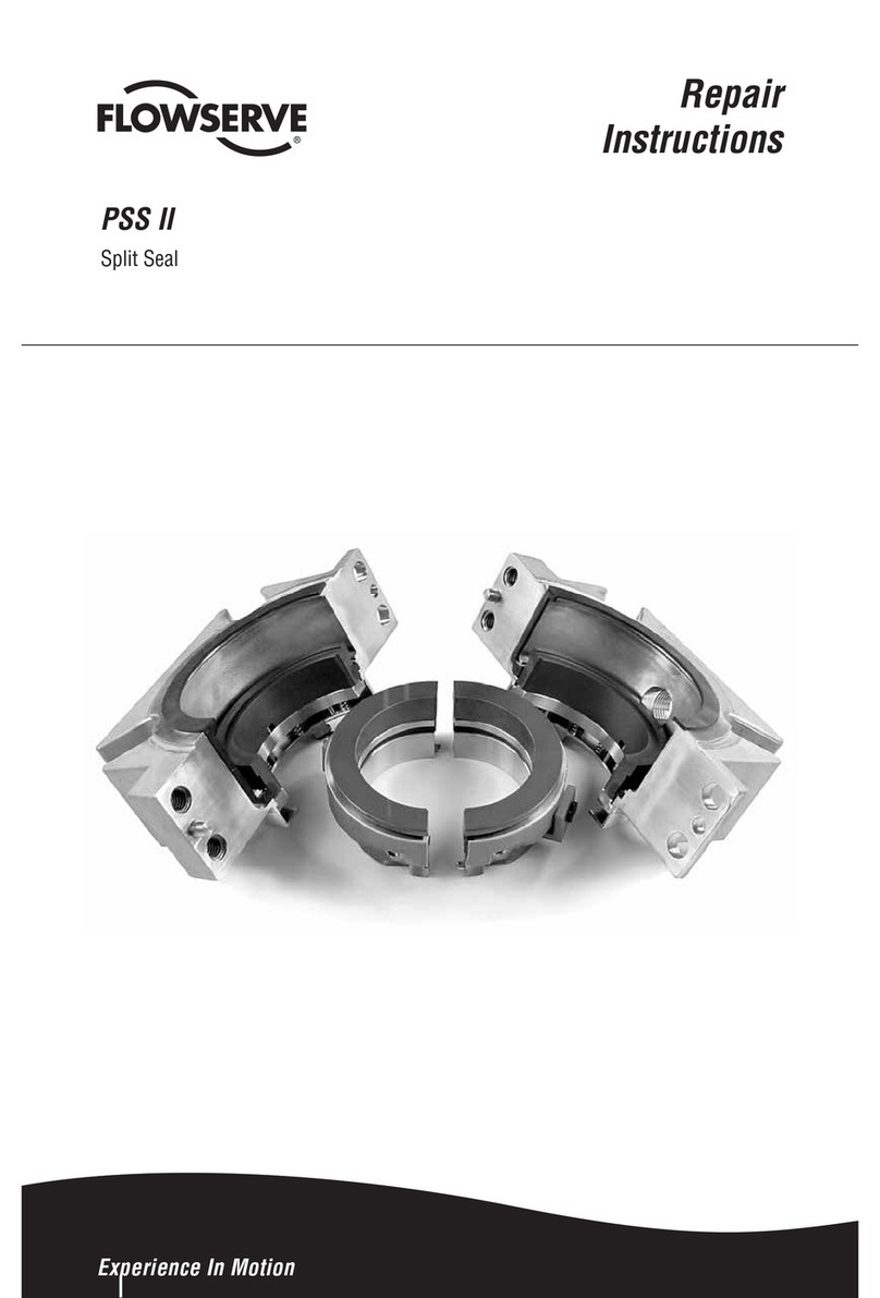
Flowserve PSS II Setup guide

Flowserve
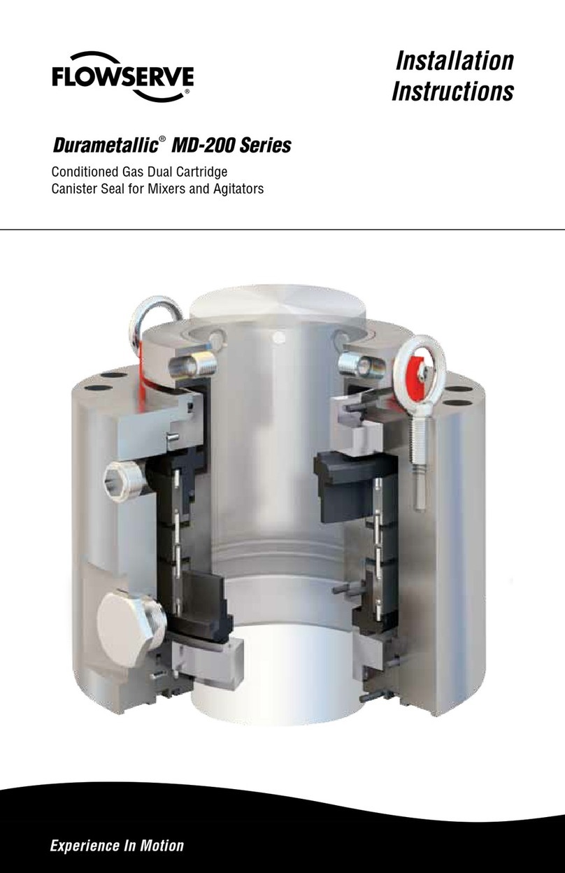
Flowserve Durametallic MD-200 Series User manual

Flowserve
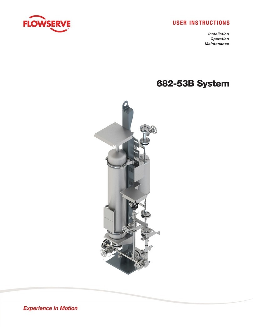
Flowserve 682-53B System User manual

Flowserve
Flowserve ISC1PX Setup guide

Flowserve
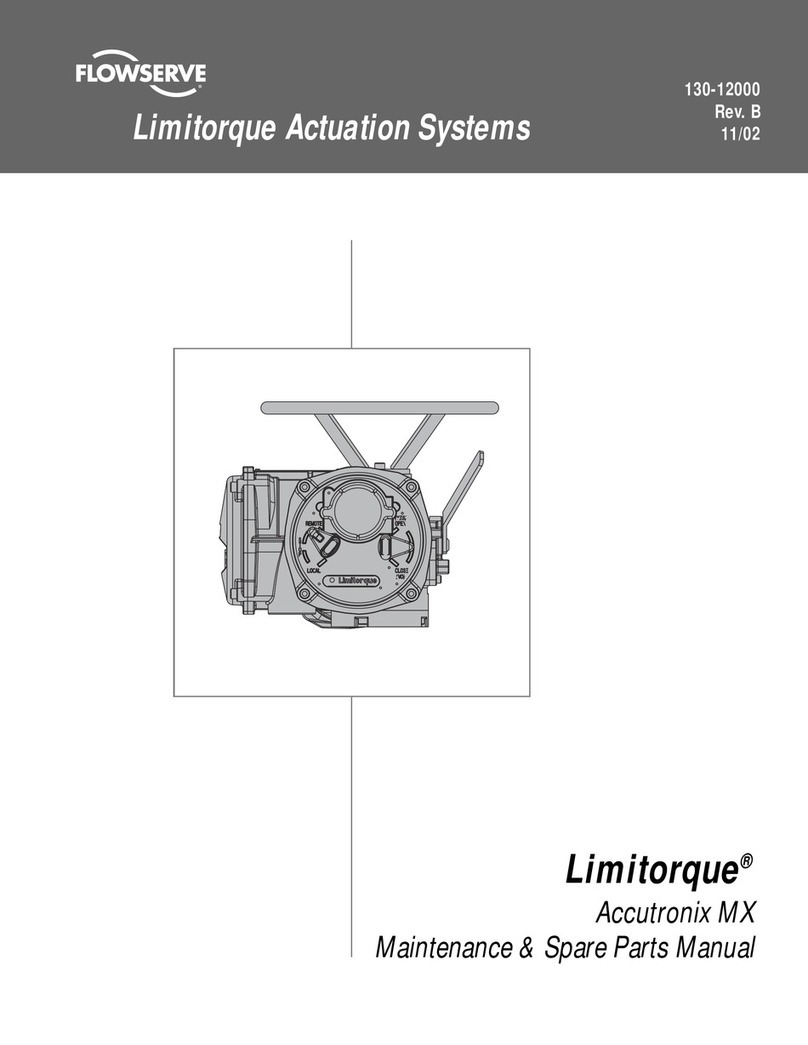
Flowserve Limitorque Accutronix MX Guide

Flowserve
Flowserve 400-D Installation instructions

Flowserve
Flowserve Limitorque HBC Series User manual