Page 3 of 36
WARNING
NO PERSONAL ALERT SAFETY SYSTEM,
RESPIRATOR OR COMBINATION OF PERSONAL
ALERT SAFETY SYSTEM AND RESPIRATOR,
BY THEMSELVES, CAN PROVIDE COMPLETE
PROTECTION IN DANGEROUS SITUATIONS.
FAILURE TO FOLLOW THE INSTRUCTIONS IN
THIS MANUAL AND THE REQUIREMENTS OF
AN ORGANIZED RESPIRATORY PROTECTION
PROGRAM MAY LEAD TO SITUATIONS WHICH
COULD RESULT IN SERIOUS INJURY OR DEATH.
WARNING
USERS OF RESPIRATORS EQUIPPED WITH THE
SEMS II DISTRESS ALARM MUST BE AWARE OF
THE PROPER OPERATION OF THE DISTRESS
ALARM. IF THE GREEN LIGHT IS NOT FLASHING
NORMALLY, OR IF THE UNIT EXHIBITS ANY
OTHER SIGNS OF A MALFUNCTION WITHOUT
THE USER TAKING PROPER CORRECTIVE
ACTION, IT MAY LEAD TO CIRCUMSTANCES
THAT RESULT IN SERIOUS INJURY OR DEATH.
SYSTEM DESCRIPTION
CONTINUED ON NEXT PAGE...
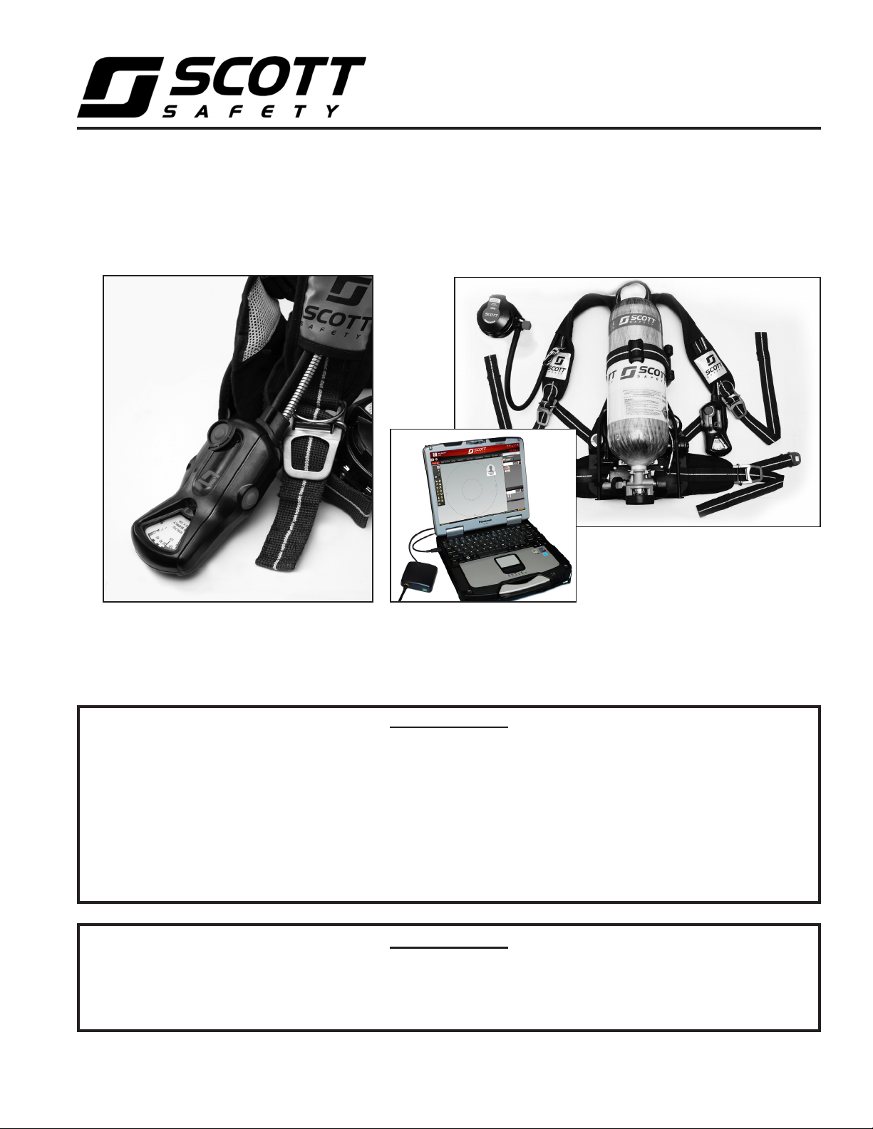
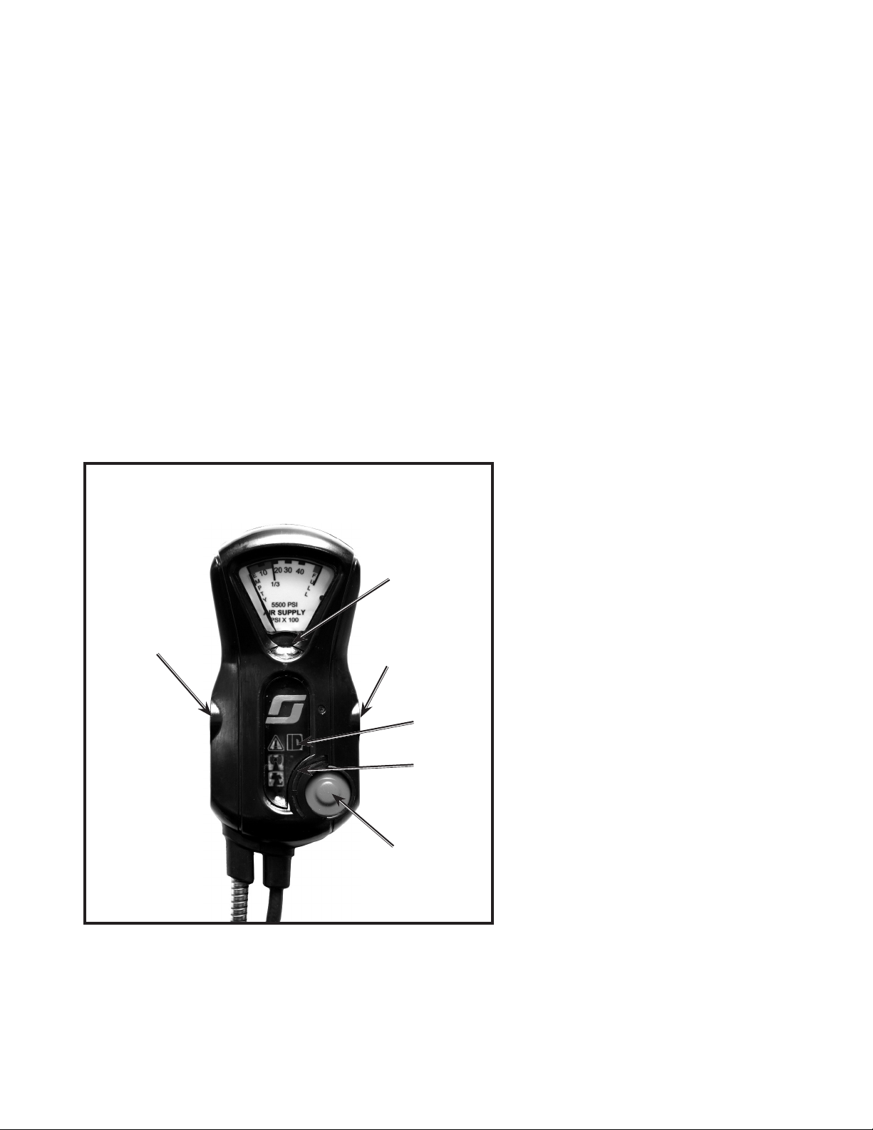
SEMS II PERSONAL DISTRESS ALARM CONTROL CONSOLE
The SCOTT SEMS II PDA Portable Unit, when added to a SCOTT SCBA respirator
consists of a Sensor Module with battery compartment mounted to the bottom of
the respirator backframe, a pressure gauge with transducer, and a Control Console
mounted on the wearer’s right shoulder strap at the pressure gauge location. The
SEMS II PDA Portable Unit requires six (6) AA batteries to operate the Sensor Module
on the backframe.
The SEMS II PDA Control Console is
integrated into the SCOTT SCBA as a
part of the remote air pressure gauge
assembly which hangs over the right
shoulder of the respirator user. The
Control Console also operates the
PERSONAL ALERT SAFETY SYSTEM
(PASS) distress alarm intended to as-
sist in locating a respirator user who is
incapacitated or in need of assistance.
The PASS distress alarm in this model
reaches FULL ALARM in a total of 30
(thirty) seconds. The Control Console
has a set of status lights, a dial air pres-
sure gauge, and three control buttons
which can easily be pressed with gloved
hands. Power is supplied by batteries in
the SEMS II PDA battery compartment
on the SCBA backframe.
WARNING
FOLLOW REGULAR OPERATIONAL INSPECTION
PROCEDURE EXACTLY. IF THE SEMS II
DISTRESS ALARM DOES NOT ACTUATE, OR IF
ANY OTHER FEATURE DOES NOT OPERATE AS
DESCRIBED OR IF ANY OTHER OPERATIONAL
MALFUNCTION IS NOTED, DO NOT USE THE
RESPIRATOR.
WARNING
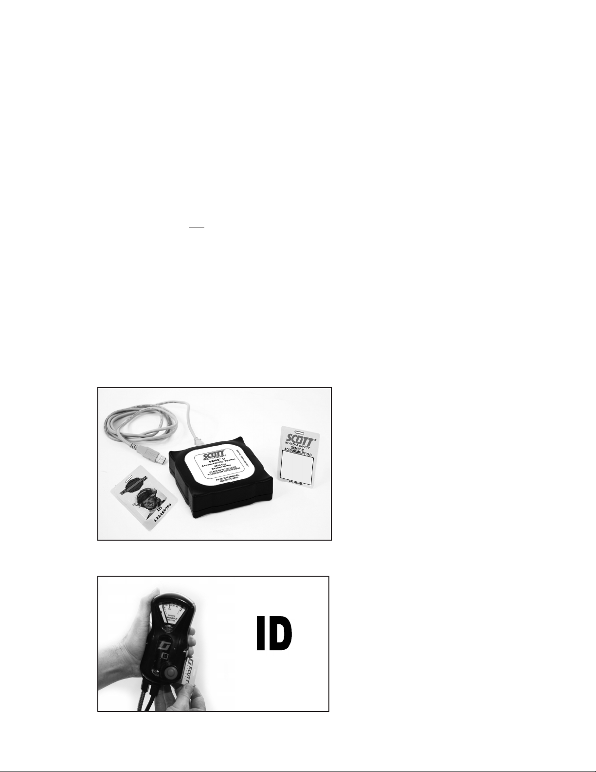
THE SEMS II ACCOUNTABILITY SYSTEM
COMMUNICATES ONLY WITH FIREFIGHTER
RESOURCES (RESPIRATOR USERS) USING
A SCOTT SCBA EQUIPPED WITH THE SEMS
II ACCOUNTABILITY SYSTEM INTEGRATED
INTO THE PERSONAL DISTRESS ALARM.
OTHER FIREFIGHTER RESOURCES WHO ARE
NOT USING A PROPERLY EQUIPPED SCOTT
RESPIRATOR MAY BE ADDED FOR ACCOUNT-
ABILITY PURPOSES, BUT THEY WILL NOT BE
AUTOMATICALLY ACCESSIBLE THROUGH
THE COMMUNICATIONS FUNCTIONS OF THE
SYSTEM. FAILURE TO RECOGNIZE THE STATUS
OF FIREFIGHTER RESOURCES MAY RESULT IN
SERIOUS INJURY OR DEATH.
the IMPERIUM software. When logged on, all the SEMS II PDA Portable Units
communicate to the Base Station directly and/or through other logged on units forming
a communications "mesh network" to the Base Station. This extends the range for
the units furthest away from the Base Station. Because of this mesh network system,
the signal strength of each user may change as the network constantly re-adjusts to
the movement of the users.
SCBAs addtionally equipped with an optional BLUETOOTH backup communication,
provide a limited one-way transmission from the control console to the Base Station
at one minute intervals via a APX™ RF Modem/ Radio network. No information can
be transmitted back to the respirator user when transmitting in BLUETOOTH mode.
In units equipped with both SEMS II and BLUETOOTH, the SEMS II is the primary
mode of communication between the console and Base Station. BLUETOOTH will
only transmit information via radio to the base station when the SEMS II is out of
range or otherwise unable to link to the system. Once the SEMS II transmission has
resumed, or the SCBA is turned off, the BLUETOOTH transmission will discontinue.
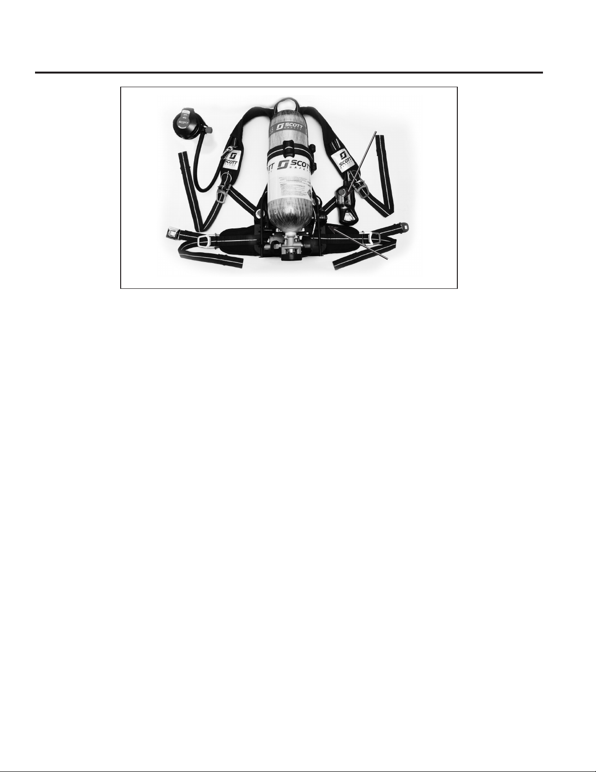
SEMS II CONTROL CONSOLES
AIR-PAK X3
MODEL
CONSOLE
NOTE
SEMS II ENABLED PDA UNITS HAVE BIDIRECTIONAL COMMUNICATION CAPABILI-
TIES AND CAN BOTH TRANSMIT AND RECEIVE DATA BETWEEN THE PDA AND
THE BASE STATION. WHEN IN BLUETOOTH MODE, BLUETOOTH ENABLED PDA
CONTROL CONSOLES ARE UNIDIRECTIONAL ONLY. THEY CAN SEND DATA TO
THE BASE STATION THROUGH APPROVED BLUETOOTH ENABLED PORTABLE
TWO-WAY RADIOS BUT CANNOT RECEIVE DATA BACK FROM THE BASE STATION.
No personal alert safety system, respirator, or combination of personal alert safety
system and respirator, by themselves, can provide complete protection in dangerous
situations. However, using an alarm and a respirator in accordance with the require-
ments of an organized respiratory protection program is one of the many safety
precautions which should be taken to avoid personal injury or death.
These instructions explain the operation and use of the main functions of the ac-
countability system. Follow the REGULAR OPERATIONAL INSPECTION procedure
as described. If any function fails to operate as described, do not use the equipment.
Remove the unit from service and tag for repair by authorized personnel.
This system communicates only with Fireghter Resources (Respirator Users) using
a SCOTT SCBA equipped with the SEMS II Accountability System integrated into the
Personal Distress Alarm.
Complete training in the use of the SEMS II and Bluetooth equipment is required
before actual use in a hazardous envirionment. If the equipment does not work as
described in these instructions, remove the equipment from service and tag for repair
by authorized personnel.