EAE E-LINEKX User manual

www.eaeelectric.com
E-LINEKX
MANUAL

E-LINEKX

CONTENTS
Introduction
General
Handling & Storage
Points To Be Taken Into Consideration Before Installation
Joint Structure
General View Of The Joint
Determination Of Special Lengths & Offset Sizing
Mounting Instructions For Joints (Bolt-on / Plug-in)
Points To Be Taken Into Consideration After Installation
Plug-in Busbar Tap Off Boxes (KXP)
Bolt-on Busbar Tap Off Boxes (KXB)
Cable Feed Box Installation (B10,B11)
Energizing / Before Energizing
Energizing The Equipment
Maintenance
2
3-4
5-6
7-8
9
10
11
12-14
15-17
18-20
21-24
25
26
27
28

www.eaeelectric.com
www.eaeelectric.com
KXMANUAL
2
Introduction
Please read the instructions contained in this publication
thoroughly and follow the directions provided carefully.
Dear Customer,
EAE Elektrik A.S. Products are designed and manufactured to provide the maximum benet in
efciency and service. Our products are manufactured in accordance with Management Systems
standards and EAE quality standards at our modern production facilities in Istanbul.
The components that you have purchased are manufactured by an environmental conscious team,
with the relevant knowledge of the Environmental Management Standards. Our employees work
strictly in accordance to the principles of the information Security Management systems, and
conform to the rules of the occupational health and safety act.
Installation, handling and operation of products should only be conducted by highly skilled, trained
and authorized personal utilizing all afliated equipment such as rubber gloves, helmet, flame
resistant clothing and glasses or face shields in accordance with the prevailing safety procedures.
9001
14001
18001
27001
ISO
N
T
E
S
M
Y
E
S
G
T
A
E
N
M
A
S
M

www.eaeelectric.com
www.eaeelectric.com
KXMANUAL
3
General
1- Installation and planning of the Busbar
system, and collaboration with other
distribution systems (mechanical, heat, steam,
air installation etc.) are crucial for the success
of the project.
2- Operational Success of the Busbar systems
are ensured by adhering to the right cartage,
design and proper installation. Incorrect
installation may cause malfunctioning,
personal injury and damage to the operating
systems.
3- The installation, operation and maintenance
of the Busbar systems should only be
performed by qualied personnel who are aware
of the dangers associated with installation,
construction, operation and intended usage,
according to the manual.
* Know the requirement of applicable electrical
laws, other laws and standards.
* Be trained and authorized to test, energize
clean, ground, label and lock the system and
equipment suitable for occupational safety
applications.
* Be trained in the use and maintenance
of personal protective equipment such as
rubber gloves, helmets, protective goggles or
face shields and flame resistant clothing in
accordance with the relevant safety practices
and potential hazardous levels.
* Must be trained in rst aid.
WARNING:
High voltage levels in the electrical components
may result in serious injury or death.
Installation, monitoring and maintenance
must be preformed on a de-energized Busbar.
Therefore, unintentional contact with energized
equipment is prevented. All warnings and
instructions must strictly be adhered to.
WARNING :
High voltage levels in the electrical components
may result in serious injury or death.Operation
of the Busbar, that is damaged by moisture
or water can cause serious personal injury or
death and damage to property. To ensure proper
installation and to remove the moisture source,
refer to the notes on page 16 item number 13.

www.eaeelectric.com
www.eaeelectric.com
KXMANUAL
4
+
General
BUSBARS SHOULD NOT BE IN
CONTACT WITH
ANY LIQUID
Dry
Envoirement Rain
Drops
Please use canopy
for outdoor
applications.
Please use porch
for outdoor.
Please use porch
for outdoor.
Please use canopy
for building expension
points.
Chemicals Urine
Water
CLOSE INDIRECT OR DIRECT
WATERWAYS.
BUSBARS THAT ARE NOT
COMPLETELY ASSEMBLED
HAVE NO PROTECTION
AGAINST WATER

www.eaeelectric.com
www.eaeelectric.com
KXMANUAL
5
Handling & Storage
1- General guidelines are provided to protect
the Busbar lengths and modules, thereby
reducing the risk of personal injury and
equipment damage handling on site.
2- As soon as the container or trucks arrives on
site, a suitable forklift is required for essay and
convenient unloading.
3- All pallets should be checked by unpacking
them to inspect for possible transit damage
and to determine that the shipment is correct
as per Packing List.
* If any of the items are missing from the
consignment or any items are damaged
during transportation. The insurance Company
must be notied immediately and all required
documents completed.
4- All Busbar lengths and modules should be
handled with care to avoid damage to internal
components and the distortion of the housing
or its nish.
KEEP DRY
HANDLE WITH
CARE STOCK VERTICALLY MAX 3 PALETTES

www.eaeelectric.com
www.eaeelectric.com www.eaeelectric.com
www.eaeelectric.com
KXMANUAL
6
Handling & Storage
5- When the Busbars and modules are required
remove them from the pallets by inserting
metal rods through the 2 sets of holes situated
at the ends of the housings, therefore ensuring
that the load is balanced and safely secured.
By using adequate slings and the slinging
method the components can be moved safetly
from one place to another.
6- The moving of products from one floor to
another floor must be performed by means of a
suitable electric, mechanical crane or elevator.
7- If storage is required before installation and
repacking is necessary it should be performed
as close as possible to the point of installation
however it should not be disassembled, until it
reaches its nal installation position depending
on various conditions. (Refer to chapter 5)
8- The Storage area should be clean and
dry with a constant temperature to prevent
condensation, having adequate air circulation
and has to be protected from dust, fumes and
moisture. The storage area should be vehicle
free to prevent damage to the products.
9- When the Busbar straight lengths and
modules are to be stored for a certain period
of time before installation. The packaging
should be repacked (if necessary) on wooden
or plastic pallets for protection during that
period. It should be stored in a protected area
and covered with a waterproof canvas which
offers protection against dust and any form of
liquid contamination.
10- The Busbars that are designed for outdoor
use is not weatherproof until the installation is
completed. The above recommended storage
parameters must be adhered to for any
remaining busbars.
8
10

7
KXMANUAL
www.eaeelectric.com
www.eaeelectric.com www.eaeelectric.com
www.eaeelectric.com
4
min. 150cm - mak. 200cm
+
Installation
Points to be taken into consideration before installation
IMPORTANT!
1- Please read the instruction manual before
commencing the Busbar installation. Incorrect
or rudimentary installation may caused
damage to the equipment or systems.
2- Installation of the Busbar systems should
only commence after understanding and
interpreting the Busbar application drawings.
Locate the positions of individual components
such as expansion units, feeder units, feeder
unit ends and transformer panel connections,
etc. These should always be executed
according to the project drawings
3-All busbar products are 100% isolation
resistance tested before shipment to our
valued customers world wide. Unloading and
storage must conform to our policies, pertaing
to environmental conditions and construction
sites. All Busbar products must be isolation
resistance tested before installation
commences, these include individual Busbar
products, single conductors (between phases:
phases and neutral and neutral and earth)
Isolation Resistance Test (min. 1000V AC) is
recommended. The measured value must not
be less than 1(one) Megaohm. All products
above 1(one) Megaohm may be installed.
Results may differ from country to country due
to environmental conditions. Commencement
of Installation without a isolation resistance
test may lead to product failure, consequently
the manufacturer (EAE Elektrik A.Ş) will not
accept liability.
4- Seismic support systems should be used
in high risk earthquake areas. Please contact
our knowledgeable sales staff for details of
seismic support products and project planning.
The recommended distance between supports
are 1.5m and the maximum is 2m. Ensure that
support positions do not obstruct joint covers
and tap off points.
5- DDT modules that are used on a concrete
floor should be positioned at intervals of 20cm.
6- If the Busbar lines are used in the transition
of the building dilatations, appropriate
dilatation modules should be chosen. Please
contact our knowledgeable staff for support.
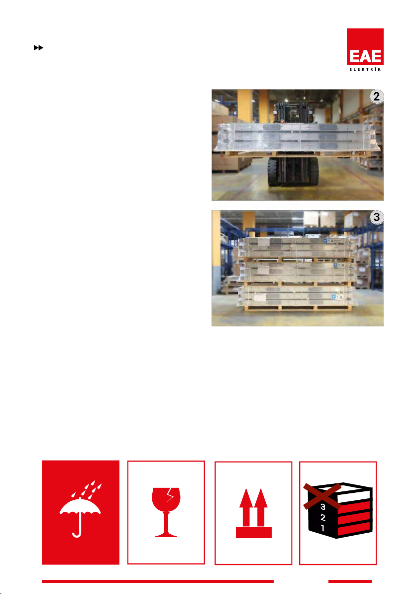
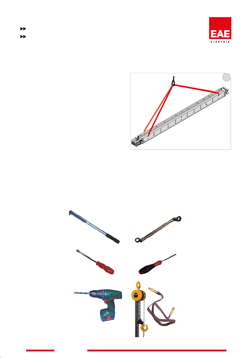
7- Busbar systems should be installed with care
when using a forklift, crane or pallet trolleys
to avoid any damage. When transporting the
products ensure that the weight is evenly
distributed. Generally vertical installation is
provided in vertical lines.
8- Please read the additional installation
instructions.
9- When installing horizontal and vertical
systems, ensure that it is aligned correctly to
prevent distortion and collapsing.
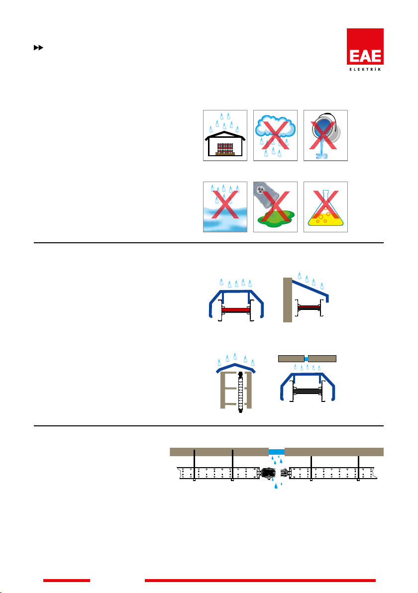
Protect the Busbar against water and moisture
from unnished roofs and walls during
installation.
Please cover
top of the shaft.

www.eaeelectric.com
www.eaeelectric.com
8
KXMANUAL
www.eaeelectric.com
www.eaeelectric.com
11
10-a 10-d
10-b 10-e
10-c
10-f
Installation
Points to be taken into consideration before installation
10- Tools required for the installation,
Micrometer, adjustable / calibrated torque
wrench
1/2 inch drive 10mm, 13mm and 19mm socket
Electric Drill
10mm Spanner/Socket
Screwdriver
Hoist with cloth sling
11- The Busbar to be installed must be secured
and hoisted as shown in the picture below.
Min. From 4 points

www.eaeelectric.com
www.eaeelectric.com
KXMANUAL
9
www.eaeelectric.com
www.eaeelectric.com
Joint Structure
1. Extruded Aluminium Housing
2. PE Fixing Piece
3. Insulation Layers (Export+Polyester
lm)
4. Joint Insulators
5. Joint Cover
6. Belleville Washer
7. Alignment Pin (removable)
8. Conductors
9. IP55 Nut Locking Piece
10. Protection Covers
11. Ip55 Joint Cover Gasket
12. Alignment Pin Slot NB Protection
covers 10 are discarded.
KX Busbars are manufactured in 3m standard
lengths, however special lengths can be
manufactured according to the project
diagrams. All modules have a block joint end
and no block joint on the opposite end.

www.eaeelectric.com
www.eaeelectric.com
10
KXMANUAL
www.eaeelectric.com
www.eaeelectric.com
Installation
General Overview Of The Joint
Bolt-on Box Mounting Point
Plug-in Box Mounting Point
Use special clamps if installation is restricted.

www.eaeelectric.com
www.eaeelectric.com
KXMANUAL
11
www.eaeelectric.com
www.eaeelectric.com
Determination of Special Lengths of Offset Sizing
1- Special lengths (particular or custom size)
busbars are used in places where standard
sizes do not t. The minimum length for these
special modules are 35cm. Please measure the
lengths of these modules as shown below
2- Length A is measured between housing
of 2 busbars in cm. "A" The special length
is calculated by deducting 25cm from this
measured length.
X=A-25 (cm) X=Length of Special Busbar (The
busbar module will be manufactured as per X
value.)
3- In the case where custom made intermediate
size Busbars are required, both ends of the
intermediate size Busbars can be produced
with or without block joints. In such cases,
please contact our knowledgeable sales staff
for technical information and support.
Note: Please supply a drawing for combined
offsets when ordering. Indicate bolted and
unbolted ends on the drawing.
325
A
X
Y
250
325
250
325
B
B
A
250
B
Y
A
A
Aluminium Copper A B X
Rated
Current
Busbar
Code
Rated
Current
Busbar
Code
(mm) (mm) (mm)
400 04 550 05 252 214 427
500 05 650 06 257 217 432
630 06 800 08 267 222 442
800 08 1000 10 282 229 457
- - 1250 12 297 236 472
1000 10 1350 14 307 241 482
- - 1600 17 322 249 497
1250 12 - - 337 256 512
1350 14 2000 23 352 264 527
1600 17 - - 387 281 562
2000 20 2500 25 427 301 602
2500 27 - - 477 326 652
- - 2000 22 377 276 552
- - 2500 27 407 291 582
2500 25 3300 32 487 331 662
- - 3600 36 517 346 692
3150 32 4000 40 547 361 722
3200 33 - - 587 381 762
4000 40 5000 50 667 421 842
5000 51 - - 767 471 942
- - 6300 63 907 541 1082
6300 63 - - 1057 617 1232
Vertical Offset
min = 250 mm
max = 490 mm
min = 300 mm
X=min:280mm, max:
Use table.
Horizontal Offset
Combined Offset

12
KXMANUAL
www.eaeelectric.com
www.eaeelectric.com
6
4
3
5
2
Installation
Mounting Instructions For Joints (Bolt-on / Plug-in)
1- Align the two Busbars so that the sections
with and without block joints are opposed.
2- Remove the protective side covers on the no
block joints.
3- Remove the nut locking piece on the busbar
joint and loosen the joint. Remove the protective
covers after loosening the joint.
4- Ensure that the insulation plates of the joint,
are not cracked, broken or damaged in anyway.
Wipe the dust off conductor surfaces with a cloth,
so that no serious damage can be caused.
5- Align the block joint to the opposite busbar's
end.
6- Loosen the nut at the connection point.
1

13
KXMANUAL
www.eaeelectric.com
www.eaeelectric.com
250mm
PE
L3
L2
L1
N
PE
L3
L2
L1
N
8
910
83
Nm
12
Installation
Mounting Instructions For Joints (Bolt-on / Plug-in)
7- Adjust the channel in order to pivot the
alignment component to the housing.
8- Coerce the two Busbars until they rest on each
other.
11- If there is more than one bolt per phase,
the bolts should be tightened by hand to
approximately 20-30 Nm as per the sequence
shown above. Then nally torque to 83Nm using
the same sequence.
12- Remove the joint covers and reverse mount
them with the gaskets facing inwards.
9- Assemble both the joint covers with the
gaskets facing outward.
First Torque
(20 Nm)
Final Torque
(83 Nm)
10- Adjust the torque wrench to 83 Nm (60 lbft)
and tighten the joint nut.
PE housing
7

14
KXMANUAL
www.eaeelectric.com
www.eaeelectric.com
Installation
Mounting Instructions For Joints (Bolt-on / Plug-in)
13- Finally tighten the locking piece to 40 Nm to
complete the installation.
14- Please complete the label attached to the
joint cover to verify that you are performing torque
settings according to the specications.
13
40
Nm
Ek / Attach
No:
Nm
83
Block Joints have been done according to
manual and applied related Nm value to
the main bolts.
Tarih / : ........./........./................Date
Ad Soyad / First / Last
: .........................................................................
İmza / : ....................................Signature
Ek montajı, talimatına uygun yapılmıştır ve
yanda yazılı Nm değerinde ek torklanmıştır.
Ek / Attach
No:
Nm
83
Block Joints have been done according to
manual and applied related Nm value to
the main bolts.
T
arh / : ........./........./................
Date
Ad Soyad / First / Last
: .........................................................................
İmza / : ....................................
Sgnature
Ek montajı, talimatına uygun yapılmıştır ve
yanda yazılı Nm değerinde ek torklanmıştır.
Abdullah Eldelekli
Abdullah Eldelekli
20 04 2014
20 04 2014
14

15
KXMANUAL
www.eaeelectric.com
www.eaeelectric.com
Installation
Points To Be Taken Into Consideration After Installation
1- When the installation has been completed,
please check the position of the neutral
conductor along the busbar run. (Taking special
care at locations where the run bends and
offsets)
2- Carry out insulation test (minimum 1000V
AC). Make sure that no protective device (switch,
connector, etc.) is connected to the system and
that the earth - neutral line is separate. All tap
off boxes on the line must be set to «0». Keep
in mind that the results can vary according to
the Busbar length, width or number of bars. The
results may also vary according to the moisture
content.
Values should not be less than 1 MegaOhm /
30 meters. It is recommended that no energy is
supplied to the line even if the insulation test is is
completed successfully.
2.3- After the Busbar system is energized,
loads must be switched on in sequence (main
and sub feed).
2.4- When the Busbar is used properly, it will
have a moderate hum. Excessive noise may
be an indication of hardware that has not been
extruded or incorrectly mounted metal parts.
2.5- Spark formation at any point along the
Busbar is abnormal. The Busbar must be de-
energized until the spark situation is rectied.
3- Do not try to install ve conductor units to
four conductor units or vice-versa.
4- Do not apply any kind of oil or chemical at
the joints or to the contacts of tap off boxes.
2.1- When the Busbar system is energized for
the rst time, qualied electrical personnel must
be present. If short circuits and earth faults are
detected due to any damage or faulty installation
practices, serious damage can occur if the power
is turned on.
2.2- When the power is supplied, there must be
no electrical load in the Busbar.
4

16
KXMANUAL
www.eaeelectric.com
www.eaeelectric.com
Installation
Points To Be Taken Into Consideration After Installation
5- Do not use any other means than original
tap off boxes to supply energy from the Busbar.
6- Current rating of the Busbar run should be
equal to the rating of the breaker. Do not exceed
Busbar nominal current during operation.
7- Make sure that any additional loads to the
system do not exceed the nominal current
capacity of the Busbar.
8- Do not use busbar system as a supporting
structure for other systems.
9- Do not use the Busbar system as a walk
way.
10- Do not light a re or use welding equipment
near the Busbar.
11- Take care when handling the system
components. Do not drop the units.
12- Do not cut or drill the busbar units. Please
take into consideration the picture below when
installing the Busbar for vertical applications.
Please do not drill the Busbar at any place
where it is marked with red on the picture.
13- Take precautions against adverse
environmental conditions such as rain and
snow an in addition, the Busbar dripping
cement etc. inside the building. Protect from
water, malfunctioning piping and all fluids that
may come from water jets. Cover if necessary.
Cap the ends of the Busbar joint points that
have not been installed after completion of the
work.
14- Ensure the selected degree of protection (IP
rating) of the system is suitable for the working
environment.
15- You can remove paint defects on product
surfaces which could happen during transporting
and installation operation by touching up with
spray paint. (Information is also available about
the paint color that you have ordered from the
manufacturer). We recommend you clean the
surfaces with a dry cloth in advance where the
painting process will be.
8
K
K
G
G
1
34
5
2
12

17
KXMANUAL
www.eaeelectric.com
www.eaeelectric.com
L3
L2
L1
N
L3
L2
L1
N
N L1 L2 L3 N L1 L2 L3
1
Installation
Points To Be Taken Into Consideration After Installation
WITHSTAND PERIODS AGAINST TO WATER AS PER STANDARD
IP55 & IP65
Vertical Shaft Application
Pressure Water 3 Min.
1- The neutral bar of KX Busbar shall be at the
bottom for horizontal Busbar lines and on the
left for vertical Busbar lines. (Figure 1)
2- In order to maintain the neutral bar at the
bottom and in the vertical Busbar on the left, it
is required to use the phase changing module.
(Figure 1)
Phase Sequence Changer
Under water 30 min.
IP67
When installation of the Tap-Off Boxes are needed after the phase changer
box, a customer representative needs to approve it in advance.
L3
L2
L1
N
-
-
-
-

18
KXMANUAL
www.eaeelectric.com
www.eaeelectric.com
Installation
Riser & Vertical Applications
As each building's structure is different. For vertical applications of the E-Line KX special projects
need to be designed.
The details on this page briefly explains the necessary information for drafting a vertical
application project.
In multi-path Busbars in high-rise vertical shaft applications; Due
to floor heights, floor thickness and product tolerances, the window or
additional point alignments on the upper floors may not be the identical.
In order for the Tap off boxes to be aligned and the joint point not to
coincide with the floor transitions, the assembly should be continued by
creating measurements on each floor.
EAE is not responsible for the potential risks that may occur in cases
where the products in our catalogue are used outside the standard phase
sequences as demonstrated in the catalogue.
N
L1
L2
L3
N
L1
L2
L3
N
L1
L2
L3
N
L1
L2
L3
150 150150 150
Other manuals for E-LINEKX
1
Table of contents
Other EAE Industrial Equipment manuals
Popular Industrial Equipment manuals by other brands

Thorne & Derrick
Thorne & Derrick Roxtec CRL 4" installation instructions

TLV
TLV RT3A instruction manual

Swiss Made
Swiss Made Swiss Rotors SF Series Operation and maintenance

Afag
Afag DG 16-W Assembly & operating instructions

Rottler
Rottler EM69P CNC 5 AXIS installation manual

RS
RS 686-935 Instruction leaflet